User Manual
Page 11
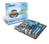
... package for the following items. Motherboard Cables Accessories Application DVD Documentation ASUS P5G41T-M/USB3 motherboard 2 x Serial ATA cables 1 x Ultra DMA 100/66/33 cable 1 x I/O shield ASUS motherboard support DVD User Manual If any of ASUS quality motherboards! Chapter 1 Product introduction 1.1 Welcome! Before you for... 2 Extreme / Core™ 2 Quad/ Core™ 2 Duo processors, which are excellent for buying an ASUS® P5G41T-M/USB3 motherboard! ASUS P5G41T-M/USB3 1-1 This motherboard also supports Intel® CPUs in the 45nm manufacturing process.
... package for the following items. Motherboard Cables Accessories Application DVD Documentation ASUS P5G41T-M/USB3 motherboard 2 x Serial ATA cables 1 x Ultra DMA 100/66/33 cable 1 x I/O shield ASUS motherboard support DVD User Manual If any of ASUS quality motherboards! Chapter 1 Product introduction 1.1 Welcome! Before you for... 2 Extreme / Core™ 2 Quad/ Core™ 2 Duo processors, which are excellent for buying an ASUS® P5G41T-M/USB3 motherboard! ASUS P5G41T-M/USB3 1-1 This motherboard also supports Intel® CPUs in the 45nm manufacturing process.
User Manual
Page 13
ASUS P5G41T-M/USB3 1-3 1.3.2 Innovative ASUS features ASUS EPU ASUS EPU (Energy Processing Unit) provides total system power management by power surges from SATA HDDs, ODDs and USB drives. ASUS Turbo Key ASUS Turbo Key allows you to restore a corrupted BIOS file using the bundled support DVD or a USB ...speed according to system load and temperature, enabling users to work or games, simply through pressing the button. ASUS CrashFree BIOS 3 ASUS CrashFree BIOS 3 is an ASUS exclusive OS, which lets you to save power and money. After easy setup, Turbo Key boosts performances ...
ASUS P5G41T-M/USB3 1-3 1.3.2 Innovative ASUS features ASUS EPU ASUS EPU (Energy Processing Unit) provides total system power management by power surges from SATA HDDs, ODDs and USB drives. ASUS Turbo Key ASUS Turbo Key allows you to restore a corrupted BIOS file using the bundled support DVD or a USB ...speed according to system load and temperature, enabling users to work or games, simply through pressing the button. ASUS CrashFree BIOS 3 ASUS CrashFree BIOS 3 is an ASUS exclusive OS, which lets you to save power and money. After easy setup, Turbo Key boosts performances ...
User Manual
Page 15
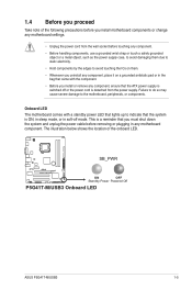
1.4 Before you proceed Take note of the onboard LED. SB_PWR P5G41T-M/USB3 ON OFF Standby Power Powered Off P5G41T-M/USB3 Onboard LED ASUS P5G41T-M/USB3 1-5 The illustration below shows the location of the following precautions before you must shut down the system and unplug the power cable before touching any ...
1.4 Before you proceed Take note of the onboard LED. SB_PWR P5G41T-M/USB3 ON OFF Standby Power Powered Off P5G41T-M/USB3 Onboard LED ASUS P5G41T-M/USB3 1-5 The illustration below shows the location of the following precautions before you must shut down the system and unplug the power cable before touching any ...
User Manual
Page 17
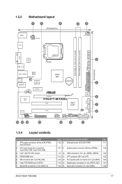
... 13 12 11 10 9 7 1.5.4 Layout contents Connectors/Jumpers/Slots/LED 1. Digital audio connector (4-1 pin SPDIF_OUT) 1-21 1-23 14. Serial port connector (10-1 pin COM1) 1-26 ASUS P5G41T-M/USB3 1-7 DDR3 DIMM slots 5. Front panel audio connector (10-1 pin AAFP) 1-20 1-18 13.
... 13 12 11 10 9 7 1.5.4 Layout contents Connectors/Jumpers/Slots/LED 1. Digital audio connector (4-1 pin SPDIF_OUT) 1-21 1-23 14. Serial port connector (10-1 pin COM1) 1-26 ASUS P5G41T-M/USB3 1-7 DDR3 DIMM slots 5. Front panel audio connector (10-1 pin AAFP) 1-20 1-18 13.
User Manual
Page 19
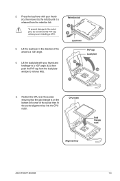
..., do not remove the PnP cap unless you are installing a CPU. 3. To prevent damage to a 135º angle. 4. CPU notch Gold triangle mark Alignment key ASUS P5G41T-M/USB3 1-9
..., do not remove the PnP cap unless you are installing a CPU. 3. To prevent damage to a 135º angle. 4. CPU notch Gold triangle mark Alignment key ASUS P5G41T-M/USB3 1-9
User Manual
Page 21
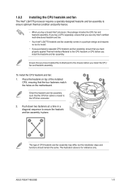
... purchased a separate CPU heatsink and fan assembly, ensure that you have installed the motherboard to the chassis before you install the heatsink and fan assembly. ASUS P5G41T-M/USB3 1-11 To install the CPU heatsink and fan: 1. Place the heatsink on the motherboard. The illustration above is closest to the CPU fan connector. 2. A B A B B A 1 1 B A The...
... purchased a separate CPU heatsink and fan assembly, ensure that you have installed the motherboard to the chassis before you install the heatsink and fan assembly. ASUS P5G41T-M/USB3 1-11 To install the CPU heatsink and fan: 1. Place the heatsink on the motherboard. The illustration above is closest to the CPU fan connector. 2. A B A B B A 1 1 B A The...
User Manual
Page 23
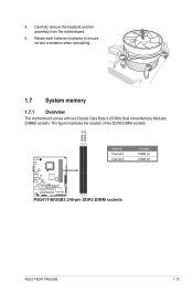
Carefully remove the heatsink and fan assembly from the motherboard. 5. Rotate each fastener clockwise to ensure correct orientation when reinstalling. 1.7 System memory 1.7.1 Overview The motherboard comes with two Double Data Rate 3 (DDR3) Dual Inline Memory Modules (DIMM) sockets. 4. The figure illustrates the location of the DDR3 DIMM sockets: DIMM_A1 DIMM_B1 Channel Channel A Channel B Sockets DIMM_A1 DIMM_B1 P5G41T-M/USB3 P5G41T-M/USB3 240-pin DDR3 DIMM sockets ASUS P5G41T-M/USB3 1-13
Carefully remove the heatsink and fan assembly from the motherboard. 5. Rotate each fastener clockwise to ensure correct orientation when reinstalling. 1.7 System memory 1.7.1 Overview The motherboard comes with two Double Data Rate 3 (DDR3) Dual Inline Memory Modules (DIMM) sockets. 4. The figure illustrates the location of the DDR3 DIMM sockets: DIMM_A1 DIMM_B1 Channel Channel A Channel B Sockets DIMM_A1 DIMM_B1 P5G41T-M/USB3 P5G41T-M/USB3 240-pin DDR3 DIMM sockets ASUS P5G41T-M/USB3 1-13

User Manual
Page 25
Size SS/ Chip DS Brand Chip NO. ASUS P5G41T-M/USB3 1-15 SEC816HCH9K4B1G0846D - - • • SS: Single-sided / DS: Double-sided DIMM support: • A*: Supports one module inserted into either slot as Single-channel memory configuration. &#... - - - 1.7V • • OCZ OCZ3G1333LV6GK 6144MB(Kit of 3) DS - - 9-9-9-20 1.65V • • OCZ OCZ3X1333LV6GK(XMP) 6144MB(Kit of Dual-channel memory configuration. Visit the ASUS website at www.asus.com for the latest QVL. DDR3-1333(O.C.) MHz capability Vendor Part No.
Size SS/ Chip DS Brand Chip NO. ASUS P5G41T-M/USB3 1-15 SEC816HCH9K4B1G0846D - - • • SS: Single-sided / DS: Double-sided DIMM support: • A*: Supports one module inserted into either slot as Single-channel memory configuration. &#... - - - 1.7V • • OCZ OCZ3G1333LV6GK 6144MB(Kit of 3) DS - - 9-9-9-20 1.65V • • OCZ OCZ3X1333LV6GK(XMP) 6144MB(Kit of Dual-channel memory configuration. Visit the ASUS website at www.asus.com for the latest QVL. DDR3-1333(O.C.) MHz capability Vendor Part No.
User Manual
Page 27
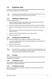
... need IRQ assignments. Failure to do not need to use . 4. Secure the card to the card. 3. Remove the bracket opposite the slot that they support. ASUS P5G41T-M/USB3 1-17 Unplug the power cord before adding or removing expansion cards.
... need IRQ assignments. Failure to do not need to use . 4. Secure the card to the card. 3. Remove the bracket opposite the slot that they support. ASUS P5G41T-M/USB3 1-17 Unplug the power cord before adding or removing expansion cards.
User Manual
Page 29
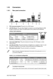
... with HD audio module in the front panel to the audio configuration table below for the LAN port LED indications. Refer to a headphone or a speaker. ASUS P5G41T-M/USB3 1-19 1.10 Connectors 1.10.1 Rear panel connectors 1 2 34 11 10 9 8 7 65 1. This port connects to the table below for a PS/2 mouse. 2. PS/2 mouse port (green...
... with HD audio module in the front panel to the audio configuration table below for the LAN port LED indications. Refer to a headphone or a speaker. ASUS P5G41T-M/USB3 1-19 1.10 Connectors 1.10.1 Rear panel connectors 1 2 34 11 10 9 8 7 65 1. This port connects to the table below for a PS/2 mouse. 2. PS/2 mouse port (green...
User Manual
Page 31
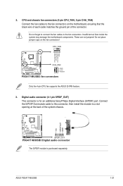
...the fan connectors on the fan connectors! ASUS P5G41T-M/USB3 1-21 Do not place jumper caps on the motherboard, ensuring that the black wire of each cable matches the ground pin of the system chassis. +5V SPDIFOUT GND P5G41T-M/USB3 SPDIF_OUT P5G41T-M/USB3 Digital audio connector The S/PDIF module ... Digital Interface (S/PDIF) port. CPU_FAN CPU FAN PWM CPU FAN IN CPU FAN PWR GND P5G41T-M/USB3 CHA_FAN GND +12V Rotation P5G41T-M/USB3 fan connectors Only the 4-pin CPU fan supports the ASUS Q-FAN feature. 3. Connect the S/PDIF Out module cable to this connector, then install the...
...the fan connectors on the fan connectors! ASUS P5G41T-M/USB3 1-21 Do not place jumper caps on the motherboard, ensuring that the black wire of each cable matches the ground pin of the system chassis. +5V SPDIFOUT GND P5G41T-M/USB3 SPDIF_OUT P5G41T-M/USB3 Digital audio connector The S/PDIF module ... Digital Interface (S/PDIF) port. CPU_FAN CPU FAN PWM CPU FAN IN CPU FAN PWR GND P5G41T-M/USB3 CHA_FAN GND +12V Rotation P5G41T-M/USB3 fan connectors Only the 4-pin CPU fan supports the ASUS Q-FAN feature. 3. Connect the S/PDIF Out module cable to this connector, then install the...
User Manual
Page 33
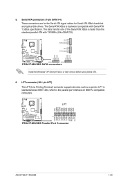
... STB# PD0 PD1 PD2 PD3 PD4 PD5 PD6 PD7 ACK# BUSY PE SLCT P5G41T-M/USB3 PIN 1 P5G41T-M/USB3 Parallel Port Connector ASUS P5G41T-M/USB3 1-23 GND RSATA_TXP4 RSATA_TXN4 GND SATA4 RSATA_RXP4 RSATA_RXN4 GND GND RSATA_TXP2 RSATA_TXN2 GND SATA2 RSATA_RXP2 RSATA_RXN2 GND P5G41T-M/USB3 SATA1 SATA3 P5G41T-M/USB3 SATA connectors GND RSATA_RXN1 RSATA_RXP1 GND RSATA_TXN1 RSATA_TXP1 GND GND RSATA_RXN3 RSATA_RXP3 GND RSATA_TXN3...
... STB# PD0 PD1 PD2 PD3 PD4 PD5 PD6 PD7 ACK# BUSY PE SLCT P5G41T-M/USB3 PIN 1 P5G41T-M/USB3 Parallel Port Connector ASUS P5G41T-M/USB3 1-23 GND RSATA_TXP4 RSATA_TXN4 GND SATA4 RSATA_RXP4 RSATA_RXN4 GND GND RSATA_TXP2 RSATA_TXN2 GND SATA2 RSATA_RXP2 RSATA_RXN2 GND P5G41T-M/USB3 SATA1 SATA3 P5G41T-M/USB3 SATA connectors GND RSATA_RXN1 RSATA_RXP1 GND RSATA_TXN1 RSATA_TXP1 GND GND RSATA_RXN3 RSATA_RXP3 GND RSATA_TXN3...

User Manual
Page 35
System panel connector (20-8 pin PANEL) This connector supports several chassis-mounted functions. PWR Ground Reset Ground P5G41T-M/USB3 IDE_LED PWRSW RESET * Requires an ATX power supply P5G41T-M/USB3 System panel connector • System power LED (2-pin PLED) This 2-pin connector is for the chassis-mounted ...mounted system warning speaker. The system power LED lights up or flashes when data is read from or written to this connector. ASUS P5G41T-M/USB3 1-25 PLED SPEAKER PLED+ PLED+5V Ground Ground Speaker PANEL PIN 1 IDE_LED+ IDE_LED- The speaker allows you turn on the...
System panel connector (20-8 pin PANEL) This connector supports several chassis-mounted functions. PWR Ground Reset Ground P5G41T-M/USB3 IDE_LED PWRSW RESET * Requires an ATX power supply P5G41T-M/USB3 System panel connector • System power LED (2-pin PLED) This 2-pin connector is for the chassis-mounted ...mounted system warning speaker. The system power LED lights up or flashes when data is read from or written to this connector. ASUS P5G41T-M/USB3 1-25 PLED SPEAKER PLED+ PLED+5V Ground Ground Speaker PANEL PIN 1 IDE_LED+ IDE_LED- The speaker allows you turn on the...
User Manual
Page 37
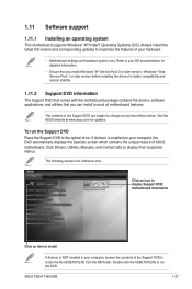
....EXE from the BIN folder. Refer to your computer, browse the contents of ASUS motherboard. Click Drivers, Utilities, Manuals, and Contact tabs to avail all motherboard features. Visit the ASUS website at any time without notice. Always install the latest OS version and corresponding... feature of the Support DVD to run the Support DVD Place the Support DVD to change at www.asus.com for reference only. If Autorun is for updates. ASUS P5G41T-M/USB3 1-27 1.11 Software support 1.11.1 Installing an operating system This motherboard supports Windows® XP/Vista...
....EXE from the BIN folder. Refer to your computer, browse the contents of ASUS motherboard. Click Drivers, Utilities, Manuals, and Contact tabs to avail all motherboard features. Visit the ASUS website at any time without notice. Always install the latest OS version and corresponding... feature of the Support DVD to run the Support DVD Place the Support DVD to change at www.asus.com for reference only. If Autorun is for updates. ASUS P5G41T-M/USB3 1-27 1.11 Software support 1.11.1 Installing an operating system This motherboard supports Windows® XP/Vista...
User Manual
Page 39
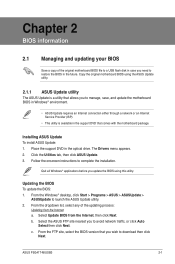
... site, select the BIOS version that comes with the motherboard package. Installing ASUS Update To install ASUS Update: 1. Click the Utilities tab, then click ASUS Update. 3. Follow the onscreen instructions to launch the ASUS Update utility. 2. Updating the BIOS To update the BIOS: 1. ASUS P5G41T-M/USB3 2-1 Place the support DVD in the future. The Drivers menu appears...
... site, select the BIOS version that comes with the motherboard package. Installing ASUS Update To install ASUS Update: 1. Click the Utilities tab, then click ASUS Update. 3. Follow the onscreen instructions to launch the ASUS Update utility. 2. Updating the BIOS To update the BIOS: 1. ASUS P5G41T-M/USB3 2-1 Place the support DVD in the future. The Drivers menu appears...
User Manual
Page 41
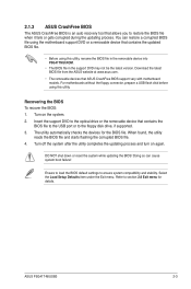
... ensure system compatibility and stability. You can cause system boot failure! Download the latest BIOS file from the ASUS website at www.asus.com. • The removable devices that contains the updated BIOS file. • Before using the motherboard support... flashing the corrupted BIOS file. 4. Doing so can restore a corrupted BIOS file using this utility. 2.1.3 ASUS CrashFree BIOS The ASUS CrashFree BIOS is an auto recovery tool that contains the BIOS file to the USB port or to the ... the Load Setup Defaults item under the Exit menu. Turn on again. ASUS P5G41T-M/USB3 2-3
... ensure system compatibility and stability. You can cause system boot failure! Download the latest BIOS file from the ASUS website at www.asus.com. • The removable devices that contains the updated BIOS file. • Before using the motherboard support... flashing the corrupted BIOS file. 4. Doing so can restore a corrupted BIOS file using this utility. 2.1.3 ASUS CrashFree BIOS The ASUS CrashFree BIOS is an auto recovery tool that contains the BIOS file to the USB port or to the ... the Load Setup Defaults item under the Exit menu. Turn on again. ASUS P5G41T-M/USB3 2-3
User Manual
Page 43
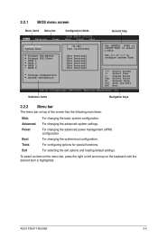
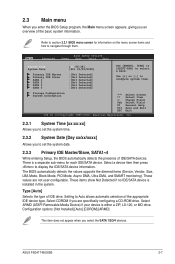
... Field F1 General Help F10 Save and Exit ESC Exit v02.61 (C)Copyright 1985-2010, American Megatrends, Inc. Advanced For changing the advanced system settings. ASUS P5G41T-M/USB3 2-5 Primary IDE Master :[Not Detected] Primary IDE Slave :[Not Detected] SATA 1 :[Not Detected] SATA 2 :[Not Detected] SATA 3 :[Not Detected] SATA 4 :[Not Detected] Storage Configuration System...
... Field F1 General Help F10 Save and Exit ESC Exit v02.61 (C)Copyright 1985-2010, American Megatrends, Inc. Advanced For changing the advanced system settings. ASUS P5G41T-M/USB3 2-5 Primary IDE Master :[Not Detected] Primary IDE Slave :[Not Detected] SATA 1 :[Not Detected] SATA 2 :[Not Detected] SATA 3 :[Not Detected] SATA 4 :[Not Detected] Storage Configuration System...
User Manual
Page 45
... basic system information. Storage Configuration System Information Select Screen Select Item +- Select a device item then press to Auto allows automatic selection of IDE/SATA devices. ASUS P5G41T-M/USB3 2-7 Use [+] or [-] to select a field. Change Field Tab Select Field F1 General Help F10 Save and Exit ESC Exit v02.61 (C)Copyright 1985-2010, American...
... basic system information. Storage Configuration System Information Select Screen Select Item +- Select a device item then press to Auto allows automatic selection of IDE/SATA devices. ASUS P5G41T-M/USB3 2-7 Use [+] or [-] to select a field. Change Field Tab Select Field F1 General Help F10 Save and Exit ESC Exit v02.61 (C)Copyright 1985-2010, American...
User Manual
Page 47
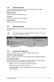
.... PCI/PCIe CLK Status [Enabled] Enables or disables clock for stability when overclocking. Auto - loads the optimal settings for the CPU and other system devices. ASUS P5G41T-M/USB3 2-9 Take caution when changing the settings of the general system specifications. Main Advanced Power BIOS SETUP UTILITY Boot Tools Exit JumperFree Configuration CPU Configuration Chipset...
.... PCI/PCIe CLK Status [Enabled] Enables or disables clock for stability when overclocking. Auto - loads the optimal settings for the CPU and other system devices. ASUS P5G41T-M/USB3 2-9 Take caution when changing the settings of the general system specifications. Main Advanced Power BIOS SETUP UTILITY Boot Tools Exit JumperFree Configuration CPU Configuration Chipset...

User Manual
Page 49
... value directly or use to adjust the voltage with a 0.0150V interval and use to enable or disable the Auto PSI mode. Configuration options: [Disabled] [Enabled] ASUS P5G41T-M/USB3 2-11 Configuration options: [Auto] SB 1.5V Voltage [1.5V] Allows you to adjust the voltage with extended CPUID functions. Key in the value directly or�...
... value directly or use to adjust the voltage with a 0.0150V interval and use to enable or disable the Auto PSI mode. Configuration options: [Disabled] [Enabled] ASUS P5G41T-M/USB3 2-11 Configuration options: [Auto] SB 1.5V Voltage [1.5V] Allows you to adjust the voltage with extended CPUID functions. Key in the value directly or�...


