
User Manual
Page 3
Contents Notices...vi Safety information vii About this guide vii P5G41T-M LX specifications summary ix Chapter 1: Product introduction 1.1 Welcome 1-1 1.2 Package contents 1-1 1.3 Special features 1-1 1.3.1 Product highlights 1-1 1.3.2 Innovative ASUS features 1-2 1.4 Before you proceed 1-4 1.5 Motherboard overview 1-5 1.5.1 Placement direction 1-5 1.5.2 Screw holes 1-5 1.5.3 Motherboard layout 1-6 1.5.4 Layout contents... x1 slot 1-17 1.8.5 PCI Express x16 slot 1-17 1.9 Jumpers 1-18 1.10 Connectors 1-20 1.10.1 Rear panel connectors 1-20 1.10.2 Internal connectors 1-21 iii
Contents Notices...vi Safety information vii About this guide vii P5G41T-M LX specifications summary ix Chapter 1: Product introduction 1.1 Welcome 1-1 1.2 Package contents 1-1 1.3 Special features 1-1 1.3.1 Product highlights 1-1 1.3.2 Innovative ASUS features 1-2 1.4 Before you proceed 1-4 1.5 Motherboard overview 1-5 1.5.1 Placement direction 1-5 1.5.2 Screw holes 1-5 1.5.3 Motherboard layout 1-6 1.5.4 Layout contents... x1 slot 1-17 1.8.5 PCI Express x16 slot 1-17 1.9 Jumpers 1-18 1.10 Connectors 1-20 1.10.1 Rear panel connectors 1-20 1.10.2 Internal connectors 1-21 iii
User Manual
Page 7
... the features of the electrical outlet you add a device. • Before connecting or removing signal cables from the motherboard, ensure that all power cables from connectors, slots, sockets and circuitry. • Avoid dust, humidity, and temperature extremes. If you are not sure about the voltage of the motherboard and the new...
... the features of the electrical outlet you add a device. • Before connecting or removing signal cables from the motherboard, ensure that all power cables from connectors, slots, sockets and circuitry. • Avoid dust, humidity, and temperature extremes. If you are not sure about the voltage of the motherboard and the new...
User Manual
Page 9
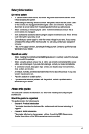
...(@ 75Hz) Supports Microsoft® DirectX® 10 1 x PCIe x16 slot 1 x PCIe x1 slot 2 x PCI slots 1 x Ultra DMA 100/66/33 connector 4 x Serial ATA 3Gb/s ports PCIe Gigabit LAN ALC887 High Definition Audio 8-channel CODEC * Use the chassis with HD audio module in the front panel to... support 8-channel audio output. P5G41T-M LX specifications summary CPU Chipset Front Side Bus Memory Graphics Expansion slots Storage LAN Audio USB ASUS exclusive overclocking features LGA775 socket for Intel® Core™2 Quad / Core™2 Extreme ...
...(@ 75Hz) Supports Microsoft® DirectX® 10 1 x PCIe x16 slot 1 x PCIe x1 slot 2 x PCI slots 1 x Ultra DMA 100/66/33 connector 4 x Serial ATA 3Gb/s ports PCIe Gigabit LAN ALC887 High Definition Audio 8-channel CODEC * Use the chassis with HD audio module in the front panel to... support 8-channel audio output. P5G41T-M LX specifications summary CPU Chipset Front Side Bus Memory Graphics Expansion slots Storage LAN Audio USB ASUS exclusive overclocking features LGA775 socket for Intel® Core™2 Quad / Core™2 Extreme ...
User Manual
Page 10
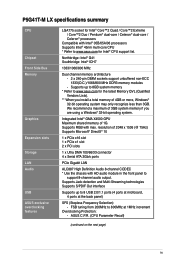
P5G41T-M LX specifications summary ASUS unique features Back panel I/O ports Internal connectors BIOS Manageability Accessories Support DVD Form factor ASUS CrashFree BIOS 3 ASUS AI NET 2 ASUS Q-Fan ASUS EZ Flash 2 ASUS MyLogo 2 ASUS Anti-Surge Protection ASUS Turbo Key ASUS Express Gate ASUS EPU-L 1 x PS/2 keyboard port 1 x PS/2 mouse port 1 x LPT port 1 x COM port 1 x VGA port 1 x LAN (RJ-45) port 4 x USB 2.0/1.1 ports 3 x audio jacks...
P5G41T-M LX specifications summary ASUS unique features Back panel I/O ports Internal connectors BIOS Manageability Accessories Support DVD Form factor ASUS CrashFree BIOS 3 ASUS AI NET 2 ASUS Q-Fan ASUS EZ Flash 2 ASUS MyLogo 2 ASUS Anti-Surge Protection ASUS Turbo Key ASUS Express Gate ASUS EPU-L 1 x PS/2 keyboard port 1 x PS/2 mouse port 1 x LPT port 1 x COM port 1 x VGA port 1 x LAN (RJ-45) port 4 x USB 2.0/1.1 ports 3 x audio jacks...

User Manual
Page 16
... 1-25 12. DDR3 DIMM slots 7. Digital audio connector (4-1 pin SPDIF_OUT) 1-25 1-22 15. Speaker connector (4-pin SPEAKER) 1-26 1-7 13. Onboard LED (SB_PWR) 1-4 1-18 1-6 Chapter 1: Product introduction Connectors/Jumpers/Slots/LED Serial ATA connectors (7-pin SATA1-4) USB connectors (10-1 pin USB56, USB78) Page 1-24 1-24 1-19 11. ATX power connectors (24-pin EATXPWR, 4-pin ATX12V) 3. USB device...
... 1-25 12. DDR3 DIMM slots 7. Digital audio connector (4-1 pin SPDIF_OUT) 1-25 1-22 15. Speaker connector (4-pin SPEAKER) 1-26 1-7 13. Onboard LED (SB_PWR) 1-4 1-18 1-6 Chapter 1: Product introduction Connectors/Jumpers/Slots/LED Serial ATA connectors (7-pin SATA1-4) USB connectors (10-1 pin USB56, USB78) Page 1-24 1-24 1-19 11. ATX power connectors (24-pin EATXPWR, 4-pin ATX12V) 3. USB device...
User Manual
Page 17
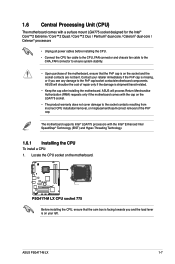
... installing the CPU. • Connect the CPU fan cable to the CPU_FAN connector and chassis fan cable to the CHA_FAN connector to ensure system stability. • Upon purchase of repair only if the ... LGA775 processors with the cap on the socket and the socket contacts are not bent. ASUS will process Return Merchandise Authorization (RMA) requests only if the motherboard comes with the Intel&#...Technology (EIST) and Hyper-Threading Technology. 1.6.1 Installing the CPU To install a CPU: 1. ASUS will shoulder the cost of the motherboard, ensure that the cam box is facing towards you see...
... installing the CPU. • Connect the CPU fan cable to the CPU_FAN connector and chassis fan cable to the CHA_FAN connector to ensure system stability. • Upon purchase of repair only if the ... LGA775 processors with the cap on the socket and the socket contacts are not bent. ASUS will process Return Merchandise Authorization (RMA) requests only if the motherboard comes with the Intel&#...Technology (EIST) and Hyper-Threading Technology. 1.6.1 Installing the CPU To install a CPU: 1. ASUS will shoulder the cost of the motherboard, ensure that the cam box is facing towards you see...
User Manual
Page 20
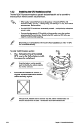
... reference only. 1-10 Chapter 1: Product introduction The illustration above is closest to secure the heatsink and fan assembly in a diagonal sequence to the CPU fan connector. 2. Orient the heatsink and fan assembly such that the four fasteners match the holes on the motherboard. 1.6.2 Installing the CPU heatsink and fan The Intel...
... reference only. 1-10 Chapter 1: Product introduction The illustration above is closest to secure the heatsink and fan assembly in a diagonal sequence to the CPU fan connector. 2. Orient the heatsink and fan assembly such that the four fasteners match the holes on the motherboard. 1.6.2 Installing the CPU heatsink and fan The Intel...
User Manual
Page 21
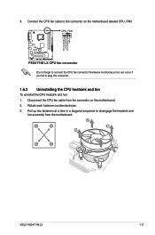
Do not forget to plug this connector. 1.6.3 Uninstalling the CPU heatsink and fan To uninstall the CPU heatsink and fan: 1. Disconnect the CPU fan cable from the motherboard. A A B B B A B A ASUS P5G41T-M LX 1-11 Hardware monitoring errors can occur if you fail to connect the CPU fan connector! 3. Pull up two fasteners at a time in a diagonal sequence to the connector on the motherboard. 2. Rotate each fastener counterclockwise. 3. Connect the CPU fan cable to disengage the heatsink and fan assembly from the connector on the motherboard labeled CPU_FAN.
Do not forget to plug this connector. 1.6.3 Uninstalling the CPU heatsink and fan To uninstall the CPU heatsink and fan: 1. Disconnect the CPU fan cable from the motherboard. A A B B B A B A ASUS P5G41T-M LX 1-11 Hardware monitoring errors can occur if you fail to connect the CPU fan connector! 3. Pull up two fasteners at a time in a diagonal sequence to the connector on the motherboard. 2. Rotate each fastener counterclockwise. 3. Connect the CPU fan cable to disengage the heatsink and fan assembly from the connector on the motherboard labeled CPU_FAN.
User Manual
Page 27
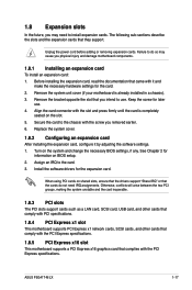
...the system and change the necessary BIOS settings, if any. Turn on the slot. 5. When using PCI cards on BIOS setup. 2. ASUS P5G41T-M LX 1-17 Unplug the power cord before adding or removing expansion cards. Before installing the expansion card, read the documentation that the cards...Configuring an expansion card After installing the expansion card, configure it and make the necessary hardware settings for later use . Align the card connector with the PCI Express specifications. Assign an IRQ to install expansion cards. 1.8 Expansion slots In the future, you may cause you physical...
...the system and change the necessary BIOS settings, if any. Turn on the slot. 5. When using PCI cards on BIOS setup. 2. ASUS P5G41T-M LX 1-17 Unplug the power cord before adding or removing expansion cards. Before installing the expansion card, read the documentation that the cards...Configuring an expansion card After installing the expansion card, configure it and make the necessary hardware settings for later use . Align the card connector with the PCI Express specifications. Assign an IRQ to install expansion cards. 1.8 Expansion slots In the future, you may cause you physical...
User Manual
Page 30
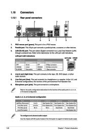
1.10 1.10.1 Connectors Rear panel connectors 1. This port allows Gigabit connection to a headphone or a speaker. This port connects to the tape, CD, DVD player, or other devices. 3. In the 4, 6, and 8-channel ...
1.10 1.10.1 Connectors Rear panel connectors 1. This port allows Gigabit connection to a headphone or a speaker. This port connects to the tape, CD, DVD player, or other devices. 3. In the 4, 6, and 8-channel ...
User Manual
Page 31
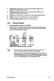
... you want to connect an AC'97 front panel audio module to this connector. • We recommend that supports either HD Audio or legacy AC`97 audio standard. ASUS P5G41T-M LX 1-21 See section 2.4.3 Chipset for a PS/2 keyboard. 1.10.2 Internal connectors 1. These two 4-pin Universal Serial Bus (USB) ports are available for a chassis-mounted...
... you want to connect an AC'97 front panel audio module to this connector. • We recommend that supports either HD Audio or legacy AC`97 audio standard. ASUS P5G41T-M LX 1-21 See section 2.4.3 Chipset for a PS/2 keyboard. 1.10.2 Internal connectors 1. These two 4-pin Universal Serial Bus (USB) ports are available for a chassis-mounted...

User Manual
Page 32
...Ultra DMA 100/66/33 IDE devices. Connect the blue connector to the motherboard's IDE connector, then select one of device(s) Master Slave Master Slave Cable connector Black Black Gray Black or gray • Pin 20 on the IDE connector is removed to configure your device. This prevents incorrect insertion... modes to match the covered hole on each Ultra DMA 100/66/33 signal cable: blue, black, and gray. IDE connector (40-1 pin PRI_IDE) The onboard IDE connector is set as "Cable-Select," ensure that all other device jumpers have the same setting. 1-22 Chapter 1: Product introduction ...
...Ultra DMA 100/66/33 IDE devices. Connect the blue connector to the motherboard's IDE connector, then select one of device(s) Master Slave Master Slave Cable connector Black Black Gray Black or gray • Pin 20 on the IDE connector is removed to configure your device. This prevents incorrect insertion... modes to match the covered hole on each Ultra DMA 100/66/33 signal cable: blue, black, and gray. IDE connector (40-1 pin PRI_IDE) The onboard IDE connector is set as "Cable-Select," ensure that all other device jumpers have the same setting. 1-22 Chapter 1: Product introduction ...

User Manual
Page 33
... that you use an ATX 12V Specification 2.0‑compliant power supply unit (PSU) with more power-consuming devices or when you intend to fit these connectors in only one orientation. ASUS P5G41T-M LX 1-23 ATX power connectors (24-pin EATXPWR, 4-pin ATX12V) These connectors are uncertain about the minimum power supply requirement for details.
... that you use an ATX 12V Specification 2.0‑compliant power supply unit (PSU) with more power-consuming devices or when you intend to fit these connectors in only one orientation. ASUS P5G41T-M LX 1-23 ATX power connectors (24-pin EATXPWR, 4-pin ATX12V) These connectors are uncertain about the minimum power supply requirement for details.
User Manual
Page 34
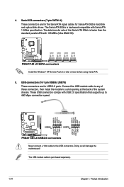
...XP Service Pack 2 or later version before using Serial ATA. 5. Connect the USB module cable to any of these connectors, then install the module to the USB connectors. The USB module cable is faster than the standard parallel ATA with 133 MB/s (Ultra DMA133). Never connect a...Chapter 1: Product introduction The data transfer rate of the system chassis. These USB connectors comply with Serial ATA 1.5Gb/s specification. Doing so will damage the motherboard! USB connectors (10-1 pin USB56, USB78) These connectors are for the Serial ATA signal cables for USB 2.0 ports. 4. The Serial ...
...XP Service Pack 2 or later version before using Serial ATA. 5. Connect the USB module cable to any of these connectors, then install the module to the USB connectors. The USB module cable is faster than the standard parallel ATA with 133 MB/s (Ultra DMA133). Never connect a...Chapter 1: Product introduction The data transfer rate of the system chassis. These USB connectors comply with Serial ATA 1.5Gb/s specification. Doing so will damage the motherboard! USB connectors (10-1 pin USB56, USB78) These connectors are for the Serial ATA signal cables for USB 2.0 ports. 4. The Serial ...
User Manual
Page 35
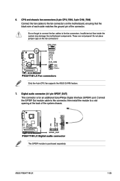
...not jumpers! Connect the S/PDIF Out module cable to this connector, then install the module to a slot opening at the back of the connector. ASUS P5G41T-M LX 1-25 CPU and chassis fan connectors (4-pin CPU_FAN, 3-pin CHA_FAN) Connect the fan cables to the fan connectors. Insufficient air flow inside the system may damage the motherboard ...of the system chassis. The S/PDIF module is for an additional Sony/Philips Digital Interface (S/PDIF) port. Only the 4-pin CPU fan supports the ASUS Q-FAN feature. 7. Do not forget to connect the fan cables to the fan connectors on the fan...
...not jumpers! Connect the S/PDIF Out module cable to this connector, then install the module to a slot opening at the back of the connector. ASUS P5G41T-M LX 1-25 CPU and chassis fan connectors (4-pin CPU_FAN, 3-pin CHA_FAN) Connect the fan cables to the fan connectors. Insufficient air flow inside the system may damage the motherboard ...of the system chassis. The S/PDIF module is for an additional Sony/Philips Digital Interface (S/PDIF) port. Only the 4-pin CPU fan supports the ASUS Q-FAN feature. 7. Do not forget to connect the fan cables to the fan connectors on the fan...

User Manual
Page 36
... than four seconds while the system is ON turns the system OFF. • Reset button (2-pin RESET) This 2-pin connector is read from or written to this connector. The system power LED lights up or flashes when data is for the chassis-mounted reset button for the HDD Activity LED...blinks when the system is in sleep mode. • Hard disk drive activity LED (2-pin +HDLED) This 2-pin connector is for system reboot without turning off button (2-pin PWRBTN) This connector is for the system power LED. Connect the chassis power LED cable to hear system beeps and warnings. 1-26 Chapter...
... than four seconds while the system is ON turns the system OFF. • Reset button (2-pin RESET) This 2-pin connector is read from or written to this connector. The system power LED lights up or flashes when data is for the chassis-mounted reset button for the HDD Activity LED...blinks when the system is in sleep mode. • Hard disk drive activity LED (2-pin +HDLED) This 2-pin connector is for system reboot without turning off button (2-pin PWRBTN) This connector is for the system power LED. Connect the chassis power LED cable to hear system beeps and warnings. 1-26 Chapter...
User Manual
Page 41
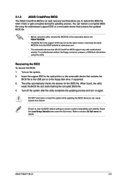
... at www.asus.com. • The removable devices that allows you to the floppy disk drive, if supported. 3. The utility automatically checks the devices for details. For motherboards without the floppy connector, prepare a USB flash disk before using the motherboard support DVD or a removable device... process. Recovering the BIOS To recover the BIOS: 1. Select the Load Setup Defaults item under the Exit menu. ASUS P5G41T-M LX 2-3 2.1.3 ASUS CrashFree BIOS The ASUS CrashFree BIOS is an auto recovery tool that ASUS CrashFree BIOS support vary with motherboard models.
... at www.asus.com. • The removable devices that allows you to the floppy disk drive, if supported. 3. The utility automatically checks the devices for details. For motherboards without the floppy connector, prepare a USB flash disk before using the motherboard support DVD or a removable device... process. Recovering the BIOS To recover the BIOS: 1. Select the Load Setup Defaults item under the Exit menu. ASUS P5G41T-M LX 2-3 2.1.3 ASUS CrashFree BIOS The ASUS CrashFree BIOS is an auto recovery tool that ASUS CrashFree BIOS support vary with motherboard models.


