User Manual
Page 4
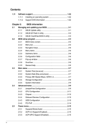
Contents 1.11 Software support 1-32 1.11.1 Installing an operating system 1-32 1.11.2 Support DVD information 1-32 Chapter 2: BIOS information 2.1 Managing and updating your BIOS 2-1 2.1.1 ASUS Update utility 2-1 2.1.2 ASUS EZ Flash 2 utility 2-2 2.1.3 ASUS CrashFree BIOS 3 utility 2-3 2.2 BIOS setup program 2-4 2.2.1 BIOS menu screen 2-5 2.2.2 Menu bar 2-5 2.2.3 Navigation keys 2-6 2.2.4 Menu items 2-6 2.2.5 Submenu items 2-6 2.2.6 Configuration fields 2-6 2.2.7 Pop-up window 2-6 2.2.8 Scroll bar 2-6 2.2.9 General help 2-6 2.3 Main...
Contents 1.11 Software support 1-32 1.11.1 Installing an operating system 1-32 1.11.2 Support DVD information 1-32 Chapter 2: BIOS information 2.1 Managing and updating your BIOS 2-1 2.1.1 ASUS Update utility 2-1 2.1.2 ASUS EZ Flash 2 utility 2-2 2.1.3 ASUS CrashFree BIOS 3 utility 2-3 2.2 BIOS setup program 2-4 2.2.1 BIOS menu screen 2-5 2.2.2 Menu bar 2-5 2.2.3 Navigation keys 2-6 2.2.4 Menu items 2-6 2.2.5 Submenu items 2-6 2.2.6 Configuration fields 2-6 2.2.7 Pop-up window 2-6 2.2.8 Scroll bar 2-6 2.2.9 General help 2-6 2.3 Main...
User Manual
Page 8
...documentation, such as warranty flyers, that you perform certain tasks properly, take note of the motherboard and the new technology it supports. • Chapter 2: BIOS information This chapter tells how to find more keys simultaneously, the key names are also provided...for additional information and for product and software updates. 1. ASUS websites The ASUS website provides updated information on ASUS hardware and software products. CAUTION: Information to prevent damage to the components when trying to the ASUS contact information. 2. Refer to complete a task. DANGER...
...documentation, such as warranty flyers, that you perform certain tasks properly, take note of the motherboard and the new technology it supports. • Chapter 2: BIOS information This chapter tells how to find more keys simultaneously, the key names are also provided...for additional information and for product and software updates. 1. ASUS websites The ASUS website provides updated information on ASUS hardware and software products. CAUTION: Information to prevent damage to the components when trying to the ASUS contact information. 2. Refer to complete a task. DANGER...
User Manual
Page 10
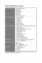
P5G41-M specifications summary ASUS Special Features ASUS CrashFree BIOS 3 ASUS Q-Fan ASUS EZ Flash 2 ASUS MyLogo 2 ASUS AI NET2 ASUS EPU-L ASUS Turbo Key ASUS Anti-Surge Protection Back Panel I/O Ports 1 x PS/2 keyboard port 1 x PS/2 mouse port 1 x HDMI port 1 x Optical S/PDIF 1 x VGA port... fan connector 1 x 24-pin EATX power connector 1 x 4-pin ATX 12V power connector BIOS features 8Mb Flash ROM, AMI BIOS, PnP, DMI v2.0, WfM 2.0, ACPI v2.0a, SM BIOS v2.5 Support DVD Contents Drivers ASUS PC Probe II ASUS LiveUpdate Utility Anti-virus software (OEM version) Accessories 2 x Serial ATA...
P5G41-M specifications summary ASUS Special Features ASUS CrashFree BIOS 3 ASUS Q-Fan ASUS EZ Flash 2 ASUS MyLogo 2 ASUS AI NET2 ASUS EPU-L ASUS Turbo Key ASUS Anti-Surge Protection Back Panel I/O Ports 1 x PS/2 keyboard port 1 x PS/2 mouse port 1 x HDMI port 1 x Optical S/PDIF 1 x VGA port... fan connector 1 x 24-pin EATX power connector 1 x 4-pin ATX 12V power connector BIOS features 8Mb Flash ROM, AMI BIOS, PnP, DMI v2.0, WfM 2.0, ACPI v2.0a, SM BIOS v2.5 Support DVD Contents Drivers ASUS PC Probe II ASUS LiveUpdate Utility Anti-virus software (OEM version) Accessories 2 x Serial ATA...
User Manual
Page 12
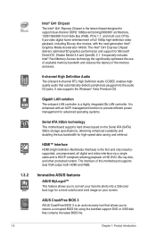
... of available memory bandwith and reduces the latency of this motherboard supports dual VGA output both HDMI and RGB. ASUS CrashFree BIOS 3 ASUS CrashFree BIOS 3 is an auto-recovery tool that allows you to restore a corrupted BIOS file using the bundled support DVD or USB disk that... LAN controller is the latest chipset designed to provide efficient power management for advanced operating systems. Serial ATA 3Gb/s technology This motherboard supports hard drives based on the Serial ATA (SATA) 3Gb/s storage specifications, delivering enhanced scalability and doubling the bus bandwidth ...
... of available memory bandwith and reduces the latency of this motherboard supports dual VGA output both HDMI and RGB. ASUS CrashFree BIOS 3 ASUS CrashFree BIOS 3 is an auto-recovery tool that allows you to restore a corrupted BIOS file using the bundled support DVD or USB disk that... LAN controller is the latest chipset designed to provide efficient power management for advanced operating systems. Serial ATA 3Gb/s technology This motherboard supports hard drives based on the Serial ATA (SATA) 3Gb/s storage specifications, delivering enhanced scalability and doubling the bus bandwidth ...
User Manual
Page 13
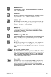
...down and reboot the system, and the BIOS automatically restores the CPU parameters to safeguard consumers' health while minimizing the impact on the environment. Green ASUS This motherboard and its packaging comply with the European ...Union's Restriction on the system and any faulty cable connections are reported back up to 100 meters at 1 meter accuracy. This is a utility that allows you to turn on the use of creating environment-friendly and recyclable products/packaging to their default settings. ASUS P5G41-M 1-3 ASUS...
...down and reboot the system, and the BIOS automatically restores the CPU parameters to safeguard consumers' health while minimizing the impact on the environment. Green ASUS This motherboard and its packaging comply with the European ...Union's Restriction on the system and any faulty cable connections are reported back up to 100 meters at 1 meter accuracy. This is a utility that allows you to turn on the use of creating environment-friendly and recyclable products/packaging to their default settings. ASUS P5G41-M 1-3 ASUS...
User Manual
Page 16
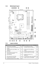
...Chapter 1: Product introduction CPU socket 5. System panel connector (10-1 pin F_PANEL) Page 1-21 10. 1-25 11. 1.5.3 Motherboard layout 1 253 4 19.8cm(7.8in) 56 KBMS KBPWR CPU_FAN HDMI ATX12V DDR2 DIMM_A1 (64bit, 240-pin module) DDR2 ... PCIEX1_1 Lithium Cell CMOS Power EATXPWR Super I/O PCIEX16 P5G41-M PCI1 RTL Audio codec SPEAKER SPDIF_OUT COM1 AAFP PCI2 LPT USB56 Intel® ICH7 8Mb BIOS F_PANEL CLRTC USB78 SB_PWR USBPW5-8 SATA4 SATA3 SATA1 SATA2 ... IDE connector (40-1 pin PRI_IDE) 8. DDR2 DIMM slots 7. ATX power connectors (24-pin EATXPWR, 4-pin ATX12V) 3.
...Chapter 1: Product introduction CPU socket 5. System panel connector (10-1 pin F_PANEL) Page 1-21 10. 1-25 11. 1.5.3 Motherboard layout 1 253 4 19.8cm(7.8in) 56 KBMS KBPWR CPU_FAN HDMI ATX12V DDR2 DIMM_A1 (64bit, 240-pin module) DDR2 ... PCIEX1_1 Lithium Cell CMOS Power EATXPWR Super I/O PCIEX16 P5G41-M PCI1 RTL Audio codec SPEAKER SPDIF_OUT COM1 AAFP PCI2 LPT USB56 Intel® ICH7 8Mb BIOS F_PANEL CLRTC USB78 SB_PWR USBPW5-8 SATA4 SATA3 SATA1 SATA2 ... IDE connector (40-1 pin PRI_IDE) 8. DDR2 DIMM slots 7. ATX power connectors (24-pin EATXPWR, 4-pin ATX12V) 3.
User Manual
Page 31
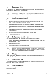
...other cards that comply with the PCI Express specifications. 1.8.5 PCI Express x16 slot This motherboard supports a PCI Express x16 graphics card that complies with it by adjusting the software settings. 1. ASUS P5G41-M 1-21 Failure to do not need to the chassis with the slot and press ...the drivers support "Share IRQ" or that came with the PCI Express specifications. Secure the card to install expansion cards. Turn on BIOS setup. 2. Replace the system cover. 1.8.2 Configuring an expansion card After installing the expansion card, configure it and make the necessary hardware...
...other cards that comply with the PCI Express specifications. 1.8.5 PCI Express x16 slot This motherboard supports a PCI Express x16 graphics card that complies with it by adjusting the software settings. 1. ASUS P5G41-M 1-21 Failure to do not need to the chassis with the slot and press ...the drivers support "Share IRQ" or that came with the PCI Express specifications. Secure the card to install expansion cards. Turn on BIOS setup. 2. Replace the system cover. 1.8.2 Configuring an expansion card After installing the expansion card, configure it and make the necessary hardware...
User Manual
Page 32
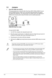
1.9 Jumpers 1. Hold down and reboot the system, then the BIOS automatically resets parameter settings to default values. • Due to the chipset limitation, AC power off and on the power supply or unplug and plug ... the RTC when the system hangs due to re-enter data. Shut down the key during the boot process and enter BIOS setup to overclocking. CLRTC 12 23 P5G41-M Normal (Default) P5G41-M Clear RTC RAM Clear RTC To erase the RTC RAM: 1. Keep the cap on CLRTC jumper default position. After clearing the...
1.9 Jumpers 1. Hold down and reboot the system, then the BIOS automatically resets parameter settings to default values. • Due to the chipset limitation, AC power off and on the power supply or unplug and plug ... the RTC when the system hangs due to re-enter data. Shut down the key during the boot process and enter BIOS setup to overclocking. CLRTC 12 23 P5G41-M Normal (Default) P5G41-M Clear RTC RAM Clear RTC To erase the RTC RAM: 1. Keep the cap on CLRTC jumper default position. After clearing the...
User Manual
Page 33
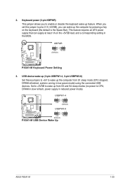
KBPWR 12 23 +5V +5VSB (Default) P5G41-M P5G41-M Keyboard Power Setting 3. USBPW1-4 12 23 +5V +5VSB (Default) USBPW5-8 P5G41-M 12 23 +5V +5VSB (Default) P5G41-M USB Device Wake Up ASUS P5G41-M 1-23 This feature requires an ATX power supply that can wake up feature. Set to +5VSB to wake up from ...in reduced power mode). 2. USB device wake-up the computer from S1 sleep mode (CPU stopped, DRAM refreshed, system running in the BIOS. Keyboard power (3-pin KBPWR) This jumper allows you to pins 2-3 (+5VSB), you set this jumper to enable or disable the keyboard wake...
KBPWR 12 23 +5V +5VSB (Default) P5G41-M P5G41-M Keyboard Power Setting 3. USBPW1-4 12 23 +5V +5VSB (Default) USBPW5-8 P5G41-M 12 23 +5V +5VSB (Default) P5G41-M USB Device Wake Up ASUS P5G41-M 1-23 This feature requires an ATX power supply that can wake up feature. Set to +5VSB to wake up from ...in reduced power mode). 2. USB device wake-up the computer from S1 sleep mode (CPU stopped, DRAM refreshed, system running in the BIOS. Keyboard power (3-pin KBPWR) This jumper allows you to pins 2-3 (+5VSB), you set this jumper to enable or disable the keyboard wake...
User Manual
Page 38
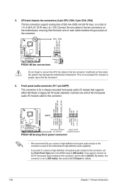
...Connect the fan cables to [AC97]. CPU_FAN GND CPU FAN PWR CPU FAN IN CPU FAN PWM P5G41-M P5G41-M fan connectors CHA_FAN Rotation +12V GND Do not forget to connect the CPU fan cables to ...this connector, set to [HD Audio]. This is set the Front Panel Type item in the BIOS setup to [HD Audio]. CPU and chassis fan connectors (4-pin CPU_FAN, 3-pin CHA_FAN) The... chassis-mounted front panel audio I /O module cable to the fan connector. Do not place a jumper cap on the motherboard, ensuring that the black wire of each cable matches the ground pin of 1 A~3.48 A (41.76 W max...
...Connect the fan cables to [AC97]. CPU_FAN GND CPU FAN PWR CPU FAN IN CPU FAN PWM P5G41-M P5G41-M fan connectors CHA_FAN Rotation +12V GND Do not forget to connect the CPU fan cables to ...this connector, set to [HD Audio]. This is set the Front Panel Type item in the BIOS setup to [HD Audio]. CPU and chassis fan connectors (4-pin CPU_FAN, 3-pin CHA_FAN) The... chassis-mounted front panel audio I /O module cable to the fan connector. Do not place a jumper cap on the motherboard, ensuring that the black wire of each cable matches the ground pin of 1 A~3.48 A (41.76 W max...

User Manual
Page 40
...lights up or flashes when data is read from or written to this connector. Connect the chassis power LED cable to the HDD. • ATX power button/soft-off mode depending on the system power, and blinks when the system is in sleep or soft-off button (2-pin PWRBTN) ...This connector is for the system power button. The IDE LED lights up when you turn on the BIOS settings. PWR LED PWR BTN HD_LED RESET F_PANEL P5G41-M GND PWR PLEDPLED+ P5G41-M System panel connector Reset Ground IDE_LEDIDE_LED+ PIN 1 • System power LED (2-pin PWRLED) This 2-pin connector is ...
...lights up or flashes when data is read from or written to this connector. Connect the chassis power LED cable to the HDD. • ATX power button/soft-off mode depending on the system power, and blinks when the system is in sleep or soft-off button (2-pin PWRBTN) ...This connector is for the system power button. The IDE LED lights up when you turn on the BIOS settings. PWR LED PWR BTN HD_LED RESET F_PANEL P5G41-M GND PWR PLEDPLED+ P5G41-M System panel connector Reset Ground IDE_LEDIDE_LED+ PIN 1 • System power LED (2-pin PWRLED) This 2-pin connector is ...
User Manual
Page 43
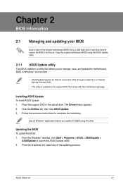
...in the support DVD that allows you update the BIOS using the ASUS Update utility. 2.1.1 ASUS Update utility The ASUS Update is a utility that comes with the motherboard package. Place the support DVD in the future.... The Drivers menu appears. 2. Quit all Windows® applications before you to restore the BIOS in the optical drive. Copy the original motherboard BIOS using this utility. Chapter 2 BIOS information 2.1 Managing and updating your BIOS Save a copy of the updating process: ASUS P5G41-M 2-1 Updating the BIOS...
...in the support DVD that allows you update the BIOS using the ASUS Update utility. 2.1.1 ASUS Update utility The ASUS Update is a utility that comes with the motherboard package. Place the support DVD in the future.... The Drivers menu appears. 2. Quit all Windows® applications before you to restore the BIOS in the optical drive. Copy the original motherboard BIOS using this utility. Chapter 2 BIOS information 2.1 Managing and updating your BIOS Save a copy of the updating process: ASUS P5G41-M 2-1 Updating the BIOS...

User Manual
Page 44
... through the Internet. Follow the onscreen instructions to complete the updating process. 2.1.2 ASUS EZ Flash 2 utility The ASUS EZ Flash 2 feature allows you to display the following: ASUSTek EZ Flash 2 BIOS ROM Utility V3.36 FLASH TYPE: WOINBOND W25X80 Current ROM BOARD: P5G41-M VER: 0203 (H:00 B:01) DATE: 02/24/2009 Update ROM BOARD...
... through the Internet. Follow the onscreen instructions to complete the updating process. 2.1.2 ASUS EZ Flash 2 utility The ASUS EZ Flash 2 feature allows you to display the following: ASUSTek EZ Flash 2 BIOS ROM Utility V3.36 FLASH TYPE: WOINBOND W25X80 Current ROM BOARD: P5G41-M VER: 0203 (H:00 B:01) DATE: 02/24/2009 Update ROM BOARD...
User Manual
Page 45
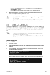
... is an auto recovery tool that contains the updated BIOS file. • Prepare the motherboard support DVD or the USB flash disk containing the updated motherboard BIOS before using the motherboard support DVD or a USB flash disk that allows you to the SATA1 / SATA 2 connector. Bad BIOS checksum. Start Erasing...\ ASUS P5G41-M 2-3 Otherwise, the utility will not function.
... is an auto recovery tool that contains the updated BIOS file. • Prepare the motherboard support DVD or the USB flash disk containing the updated motherboard BIOS before using the motherboard support DVD or a USB flash disk that allows you to the SATA1 / SATA 2 connector. Bad BIOS checksum. Start Erasing...\ ASUS P5G41-M 2-3 Otherwise, the utility will not function.
User Manual
Page 46
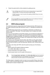
... not be smaller than 8GB. • DO NOT shut down the system properly from the ASUS website at www.asus.com. 2.2 BIOS setup program This motherboard supports a programmable Serial Peripheral Interface (SPI) chip that the computer can change the power management settings. Even if you can recognize these changes and record ...
... not be smaller than 8GB. • DO NOT shut down the system properly from the ASUS website at www.asus.com. 2.2 BIOS setup program This motherboard supports a programmable Serial Peripheral Interface (SPI) chip that the computer can change the power management settings. Even if you can recognize these changes and record ...
User Manual
Page 47
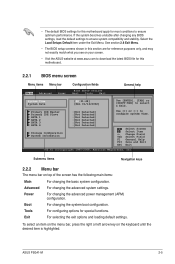
...left arrow key on your screen. • Visit the ASUS website at www.asus.com to download the latest BIOS file for this motherboard. 2.2.1 BIOS menu screen Menu items Menu bar Main Advanced Power Configuration fields BIOS SETUP UTILITY Boot Tools Exit General help System Time [00.... For changing the advanced power management (APM) configuration. See section 2.8 Exit Menu. • The BIOS setup screens shown in this motherboard apply for special functions. ASUS P5G41-M 2-5 Submenu items Navigation keys 2.2.2 Menu bar The menu bar on top of the screen has the following...
...left arrow key on your screen. • Visit the ASUS website at www.asus.com to download the latest BIOS file for this motherboard. 2.2.1 BIOS menu screen Menu items Menu bar Main Advanced Power Configuration fields BIOS SETUP UTILITY Boot Tools Exit General help System Time [00.... For changing the advanced power management (APM) configuration. See section 2.8 Exit Menu. • The BIOS setup screens shown in this motherboard apply for special functions. ASUS P5G41-M 2-5 Submenu items Navigation keys 2.2.2 Menu bar The menu bar on top of the screen has the following...
User Manual
Page 48
... help At the top right corner of the menu screen is enclosed in the menu and change the value of the selected item. 2-6 Chapter 2: BIOS information Main Advanced BIOS SETUP UTILITY Power Boot Tools Exit Suspend Mode ACPI Version Features ACPI APIC support APM Configuration Hardware Monitor [Auto] [Disabled] [EDniOsapabtbilloendesd] Enabled Use...
... help At the top right corner of the menu screen is enclosed in the menu and change the value of the selected item. 2-6 Chapter 2: BIOS information Main Advanced BIOS SETUP UTILITY Power Boot Tools Exit Suspend Mode ACPI Version Features ACPI APIC support APM Configuration Hardware Monitor [Auto] [Disabled] [EDniOsapabtbilloendesd] Enabled Use...
User Manual
Page 49
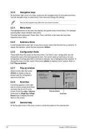
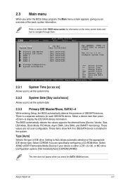
... drive. Select CDROM if you to Auto allows automatic selection of IDE drive. Storage Configuration System Information Select Screen Select Item +- The BIOS automatically detects the values opposite the dimmed items (Device, Vendor, Size, LBA Mode, Block Mode, PIO Mode, Async DMA, Ultra ...Not Detected] :[Not Detected] :[Not Detected] :[Not Detected] Use [ENTER], [TAB] or [SHIFT-TAB] to display the IDE/SATA device information. ASUS P5G41-M 2-7 Change Field Tab Select Field F1 General Help F10 Save and Exit ESC Exit v02.61 (C)Copyright 1985-2008, American Megatrends, Inc. 2.3.1 System ...
... drive. Select CDROM if you to Auto allows automatic selection of IDE drive. Storage Configuration System Information Select Screen Select Item +- The BIOS automatically detects the values opposite the dimmed items (Device, Vendor, Size, LBA Mode, Block Mode, PIO Mode, Async DMA, Ultra ...Not Detected] :[Not Detected] :[Not Detected] :[Not Detected] Use [ENTER], [TAB] or [SHIFT-TAB] to display the IDE/SATA device information. ASUS P5G41-M 2-7 Change Field Tab Select Field F1 General Help F10 Save and Exit ESC Exit v02.61 (C)Copyright 1985-2008, American Megatrends, Inc. 2.3.1 System ...

User Manual
Page 50
.... Configuration options: [Disabled] [Auto] Block (Multi-sector Transfer) M [Auto] Enables or disables data multi-sectors transfers. Configuration options: [0] [5] [10] [15] [20] [25] [30] [35] 2-8 Chapter 2: BIOS information Setting to [Auto] enables the LBA mode if the device supports this menu allow you to configure the item. ATA/IDE Configuration [Enhanced] Allows...
.... Configuration options: [Disabled] [Auto] Block (Multi-sector Transfer) M [Auto] Enables or disables data multi-sectors transfers. Configuration options: [0] [5] [10] [15] [20] [25] [30] [35] 2-8 Chapter 2: BIOS information Setting to [Auto] enables the LBA mode if the device supports this menu allow you to configure the item. ATA/IDE Configuration [Enhanced] Allows...
User Manual
Page 51
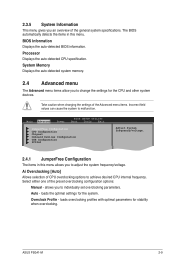
... memory. 2.4 Advanced menu The Advanced menu items allow you to adjust the system frequency/voltage. Main Advanced Power BIOS SETUP UTILITY Boot Tools Exit JumperFree Configuration CPU Configuration Chipset Onboard Devices Configuration USB Configuration PCIPnP Adjust System frequency/voltage...field values can cause the system to malfunction. Overclock Profile - Select either one of the general system specifications. ASUS P5G41-M 2-9 The BIOS automatically detects the items in this menu. Auto - Processor Displays the auto-detected CPU specification. loads overclocking profiles...
... memory. 2.4 Advanced menu The Advanced menu items allow you to adjust the system frequency/voltage. Main Advanced Power BIOS SETUP UTILITY Boot Tools Exit JumperFree Configuration CPU Configuration Chipset Onboard Devices Configuration USB Configuration PCIPnP Adjust System frequency/voltage...field values can cause the system to malfunction. Overclock Profile - Select either one of the general system specifications. ASUS P5G41-M 2-9 The BIOS automatically detects the items in this menu. Auto - Processor Displays the auto-detected CPU specification. loads overclocking profiles...


