
User Manual
Page 1
P5G41-M Motherboard
P5G41-M Motherboard
User Manual
Page 3
Contents Notices...vi Safety information vii About this guide viii P5G41-M specifications summary ix Chapter 1: Product introduction 1.1 Welcome 1-1 1.2 Package contents 1-1 1.3 Special features 1-1 1.3.1 Product highlights 1-1 1.3.2 Innovative ASUS features 1-2 1.4 Before you proceed 1-4 1.5 Motherboard overview 1-5 1.5.1 Placement direction 1-5 1.5.2 Screw holes 1-5 1.5.3 Motherboard layout 1-6 1.5.4 Layout contents 1-6 1.6 Central Processing Unit (CPU 1-7 1.6.1 Installing the CPU 1-7 1.6.2 Installing the CPU heatsink and fan 1-10 1.6.3 Uninstalling...
Contents Notices...vi Safety information vii About this guide viii P5G41-M specifications summary ix Chapter 1: Product introduction 1.1 Welcome 1-1 1.2 Package contents 1-1 1.3 Special features 1-1 1.3.1 Product highlights 1-1 1.3.2 Innovative ASUS features 1-2 1.4 Before you proceed 1-4 1.5 Motherboard overview 1-5 1.5.1 Placement direction 1-5 1.5.2 Screw holes 1-5 1.5.3 Motherboard layout 1-6 1.5.4 Layout contents 1-6 1.6 Central Processing Unit (CPU 1-7 1.6.1 Installing the CPU 1-7 1.6.2 Installing the CPU heatsink and fan 1-10 1.6.3 Uninstalling...
User Manual
Page 6
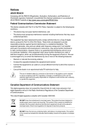
... device must accept any interference received including interference that the battery should not be placed in our products at ASUS REACH website at http://green.asus.com/english/REACH.htm. DO NOT throw the motherboard in municipal waste. DO NOT throw the mercury-containing button cell battery in municipal waste. This symbol of...
... device must accept any interference received including interference that the battery should not be placed in our products at ASUS REACH website at http://green.asus.com/english/REACH.htm. DO NOT throw the motherboard in municipal waste. DO NOT throw the mercury-containing button cell battery in municipal waste. This symbol of...
User Manual
Page 7
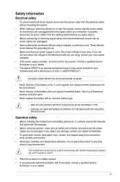
...the voltage of the electrical outlet you detect any area where it to a hazardous material collection point. • Never replace the battery with your motherboard) and is an optional component (may or may become wet. If you are using an adpater or extension cord. Operation safety • Before... product in any damage, contact your dealer immediately. • To avoid short circuits, keep paper clips, screws, and staples away from the motherboard, ensure that your power supply is broken, do not try to fix it , carefully read all the manuals that the power cables for the...
...the voltage of the electrical outlet you detect any area where it to a hazardous material collection point. • Never replace the battery with your motherboard) and is an optional component (may or may become wet. If you are using an adpater or extension cord. Operation safety • Before... product in any damage, contact your dealer immediately. • To avoid short circuits, keep paper clips, screws, and staples away from the motherboard, ensure that your power supply is broken, do not try to fix it , carefully read all the manuals that the power cables for the...
User Manual
Page 8
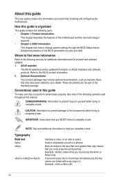
... and software products. Typography Bold text Italics ++ Indicates a menu or an item to the ASUS contact information. 2. Example: means that you must press the enclosed key. Refer to select. These documents are linked with a plus sign (+). ... task. About this guide is organized This guide contains the following parts: • Chapter 1: Product introduction This chapter describes the features of the motherboard and the new technology it supports. • Chapter 2: BIOS information This chapter tells how to change system settings through the BIOS Setup menus. ...
... and software products. Typography Bold text Italics ++ Indicates a menu or an item to the ASUS contact information. 2. Example: means that you must press the enclosed key. Refer to select. These documents are linked with a plus sign (+). ... task. About this guide is organized This guide contains the following parts: • Chapter 1: Product introduction This chapter describes the features of the motherboard and the new technology it supports. • Chapter 2: BIOS information This chapter tells how to change system settings through the BIOS Setup menus. ...

User Manual
Page 11
... supports Intel® CPUs in your motherboard package for buying an ASUS® P5G41-M motherboard! Before you for the following items. Motherboard Cables Accessories Application DVD Documentation ASUS P5G41-M motherboard 2 x Serial ATA cables 1 x Ultra DMA 100/66 cable 1 x I/O shield ASUS motherboard support DVD User Manual If any of ASUS quality motherboards! ASUS P5G41-M 1-1 Thank you start installing the motherboard, and hardware devices on it another...
... supports Intel® CPUs in your motherboard package for buying an ASUS® P5G41-M motherboard! Before you for the following items. Motherboard Cables Accessories Application DVD Documentation ASUS P5G41-M motherboard 2 x Serial ATA cables 1 x Ultra DMA 100/66 cable 1 x I/O shield ASUS motherboard support DVD User Manual If any of ASUS quality motherboards! ASUS P5G41-M 1-1 Thank you start installing the motherboard, and hardware devices on it another...
User Manual
Page 12
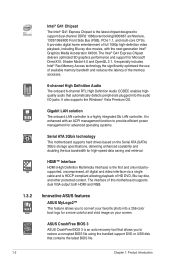
...667 architecture, 1333/1066/800 Front Side Bus (FSB), PCIe 1.1, and multi-core CPUs. ASUS CrashFree BIOS 3 ASUS CrashFree BIOS 3 is HDCP compliant allowing playback of this motherboard supports dual VGA output both HDMI and RGB. It also supports the Windows® Vista Premium ...to provide efficient power management for advanced operating systems. Serial ATA 3Gb/s technology This motherboard supports hard drives based on your favorite photo into the audio I/O jacks. Innovative ASUS features ASUS MyLogo2™ This feature allows you to convert your screen. HDMI™ Interface...
...667 architecture, 1333/1066/800 Front Side Bus (FSB), PCIe 1.1, and multi-core CPUs. ASUS CrashFree BIOS 3 ASUS CrashFree BIOS 3 is HDCP compliant allowing playback of this motherboard supports dual VGA output both HDMI and RGB. It also supports the Windows® Vista Premium ...to provide efficient power management for advanced operating systems. Serial ATA 3Gb/s technology This motherboard supports hard drives based on your favorite photo into the audio I/O jacks. Innovative ASUS features ASUS MyLogo2™ This feature allows you to convert your screen. HDMI™ Interface...
User Manual
Page 13
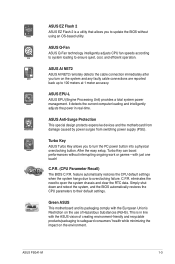
... boost performances without using an OS-based utility. ASUS P5G41-M 1-3 C.P.R. eliminates the need to overclocking failure. This is a utility that allows you to 100 meters at 1 meter accuracy. C.P.R. (CPU Parameter Recall) The BIOS C.P.R. Green ASUS This motherboard and its packaging comply with just one touch! ASUS Q-Fan ASUS Q-Fan technology intelligently adjusts CPU fan speeds according...
... boost performances without using an OS-based utility. ASUS P5G41-M 1-3 C.P.R. eliminates the need to overclocking failure. This is a utility that allows you to 100 meters at 1 meter accuracy. C.P.R. (CPU Parameter Recall) The BIOS C.P.R. Green ASUS This motherboard and its packaging comply with just one touch! ASUS Q-Fan ASUS Q-Fan technology intelligently adjusts CPU fan speeds according...
User Manual
Page 14
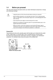
... P5G41-M P5G41-M Onboard LED ON OFF Standy Power Powered Off 1-4 Chapter 1: Product introduction The illustration below shows the location of the following precautions before you install motherboard components or change any motherboard settings. • Unplug the power cord from the power supply. Onboard LED The motherboard comes... bag that came with a standby power LED that lights up to the motherboard, peripherals, or components. Failure to do so may cause severe damage to indicate that the ATX power supply is detached from the wall socket before removing or plugging in...
... P5G41-M P5G41-M Onboard LED ON OFF Standy Power Powered Off 1-4 Chapter 1: Product introduction The illustration below shows the location of the following precautions before you install motherboard components or change any motherboard settings. • Unplug the power cord from the power supply. Onboard LED The motherboard comes... bag that came with a standby power LED that lights up to the motherboard, peripherals, or components. Failure to do so may cause severe damage to indicate that the ATX power supply is detached from the wall socket before removing or plugging in...
User Manual
Page 15
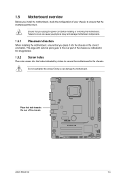
... edge with external ports goes to the rear part of your chassis to do so can damage the motherboard. Place this side towards the rear of the chassis P5G41-M ASUS P5G41-M 1-5 Failure to ensure that the motherboard fits into the chassis in the image below. 1.5.2 Screw holes Place six screws into the holes indicated by...
... edge with external ports goes to the rear part of your chassis to do so can damage the motherboard. Place this side towards the rear of the chassis P5G41-M ASUS P5G41-M 1-5 Failure to ensure that the motherboard fits into the chassis in the image below. 1.5.2 Screw holes Place six screws into the holes indicated by...
User Manual
Page 16
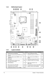
ATX power connectors (24-pin EATXPWR, 4-pin ATX12V) 3. System panel connector (10-1 pin F_PANEL) Page 1-21 10. 1-25 11. Front panel audio connector (10-pin AAFP) 1-4 17. 1.5.3 Motherboard layout 1 253 4 19.8cm(7.8in) 56 KBMS ...KBPWR CPU_FAN HDMI ATX12V DDR2 DIMM_A1 (64bit, 240-pin module) DDR2 DIMM_B1 (64bit, 240-pin module) PRI_IDE 24.4cm(9.6in) LGA775 7 VGA USB34 USBPW1-4 LAN1_USB12 Atheros L1E Intel® G41 SPDIF_O ICS 9LRS954 AUDIO 2 PCIEX1_1 Lithium Cell CMOS Power EATXPWR Super I/O PCIEX16 P5G41...
ATX power connectors (24-pin EATXPWR, 4-pin ATX12V) 3. System panel connector (10-1 pin F_PANEL) Page 1-21 10. 1-25 11. Front panel audio connector (10-pin AAFP) 1-4 17. 1.5.3 Motherboard layout 1 253 4 19.8cm(7.8in) 56 KBMS ...KBPWR CPU_FAN HDMI ATX12V DDR2 DIMM_A1 (64bit, 240-pin module) DDR2 DIMM_B1 (64bit, 240-pin module) PRI_IDE 24.4cm(9.6in) LGA775 7 VGA USB34 USBPW1-4 LAN1_USB12 Atheros L1E Intel® G41 SPDIF_O ICS 9LRS954 AUDIO 2 PCIEX1_1 Lithium Cell CMOS Power EATXPWR Super I/O PCIEX16 P5G41...
User Manual
Page 17
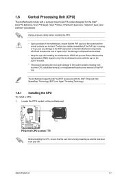
...® Enhanced Intel SpeedStep® Technology (EIST) and Hyper-Threading Technology. 1.6.1 Installing the CPU To install a CPU: 1. P5G41-M P5G41-M CPU socket 775 Before installing the CPU, ensure that the PnP cap is on the motherboard. ASUS P5G41-M 1-7 Locate the CPU socket on your retailer immediately if the PnP cap is missing, or if you and...
...® Enhanced Intel SpeedStep® Technology (EIST) and Hyper-Threading Technology. 1.6.1 Installing the CPU To install a CPU: 1. P5G41-M P5G41-M CPU socket 775 Before installing the CPU, ensure that the PnP cap is on the motherboard. ASUS P5G41-M 1-7 Locate the CPU socket on your retailer immediately if the PnP cap is missing, or if you and...

User Manual
Page 20
To install the CPU heatsink and fan: 1. Place the heatsink on the motherboard. A B A B B A 1 1 B A The type of the installed CPU, ensuring that you have installed the motherboard to the chassis before you have properly applied Thermal Interface Material to the CPU fan connector. 2. The illustration above is closest to the CPU heatsink ...
To install the CPU heatsink and fan: 1. Place the heatsink on the motherboard. A B A B B A 1 1 B A The type of the installed CPU, ensuring that you have installed the motherboard to the chassis before you have properly applied Thermal Interface Material to the CPU fan connector. 2. The illustration above is closest to the CPU heatsink ...

User Manual
Page 21
... disengage the heatsink and fan assembly from the connector on the motherboard labeled CPU_FAN. Hardware monitoring errors can occur if you fail to connect the CPU fan connector! A B A B B A B A ASUS P5G41-M 1-11 CPU_FAN GND CPU FAN PWR CPU FAN IN CPU FAN PWM P5G41-M P5G41-M CPU fan connector Do not forget to plug this connector. 1.6.3 Uninstalling...
... disengage the heatsink and fan assembly from the connector on the motherboard labeled CPU_FAN. Hardware monitoring errors can occur if you fail to connect the CPU fan connector! A B A B B A B A ASUS P5G41-M 1-11 CPU_FAN GND CPU FAN PWR CPU FAN IN CPU FAN PWM P5G41-M P5G41-M CPU fan connector Do not forget to plug this connector. 1.6.3 Uninstalling...
User Manual
Page 22
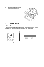
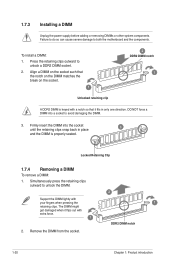
The figure illustrates the location of the DDR2 DIMM sockets: DIMM_A1 DIMM_B1 P5G41-M Channel Channel A Channel B P5G41-M 240-pin DDR2 DIMM sockets Sockets DIMM_A1 DIMM_B1 1-12 Chapter 1: Product introduction 4. Rotate each fastener clockwise to ensure correct orientation when reinstalling. 1.7 System memory 1.7.1 Overview The motherboard comes with two Double Data Rate 2 (DDR2) Dual Inline Memory Modules (DIMM) sockets. Carefully remove the heatsink and fan assembly from the motherboard. 5.
The figure illustrates the location of the DDR2 DIMM sockets: DIMM_A1 DIMM_B1 P5G41-M Channel Channel A Channel B P5G41-M 240-pin DDR2 DIMM sockets Sockets DIMM_A1 DIMM_B1 1-12 Chapter 1: Product introduction 4. Rotate each fastener clockwise to ensure correct orientation when reinstalling. 1.7 System memory 1.7.1 Overview The motherboard comes with two Double Data Rate 2 (DDR2) Dual Inline Memory Modules (DIMM) sockets. Carefully remove the heatsink and fan assembly from the motherboard. 5.

User Manual
Page 23
...modules for manual memory frequency adjustment. • Some old-version DDR2-800 DIMMs may operate at a lower frequency than the vendor-marked value. ASUS P5G41-M 1-13 To operate at the vendor-marked or at a higher frequency, see section 2.4 Advanced menu for overclocking may not match Intel®'s..., adjust the memory timing manually. Use a maximum of 3GB system memory if you install 4GB or more memory on the motherboard. • This motherboard does not support DIMMs made up to the memory address limitation on Windows® XP Professional x64 and Windows® Vista x64...
...modules for manual memory frequency adjustment. • Some old-version DDR2-800 DIMMs may operate at a lower frequency than the vendor-marked value. ASUS P5G41-M 1-13 To operate at the vendor-marked or at a higher frequency, see section 2.4 Advanced menu for overclocking may not match Intel®'s..., adjust the memory timing manually. Use a maximum of 3GB system memory if you install 4GB or more memory on the motherboard. • This motherboard does not support DIMMs made up to the memory address limitation on Windows® XP Professional x64 and Windows® Vista x64...
User Manual
Page 24
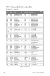
...; AET93R300B 0634 •• AET93R300B 0639 • • AENEON AET860UD0030DB08X 5 AENEON DS AET03F30DB 0730 • • (continued on the next page) 1-14 Chapter 1: Product introduction P5G41-M Motherboard Qualified Vendors Lists (QVL) DDR2-667 MHz capability Size 512MB 1GB 2GB 1GB 512MB 512MB 512MB 2GB 1GB 1GB 1GB 1GB 4GB (2 x 2GB) 2GB (2 x 1GB...
...; AET93R300B 0634 •• AET93R300B 0639 • • AENEON AET860UD0030DB08X 5 AENEON DS AET03F30DB 0730 • • (continued on the next page) 1-14 Chapter 1: Product introduction P5G41-M Motherboard Qualified Vendors Lists (QVL) DDR2-667 MHz capability Size 512MB 1GB 2GB 1GB 512MB 512MB 512MB 2GB 1GB 1GB 1GB 1GB 4GB (2 x 2GB) 2GB (2 x 1GB...
User Manual
Page 30
... a DIMM Unplug the power supply before adding or removing DIMMs or other system components. To install a DIMM: 1. Press the retaining clips outward to both the motherboard and the components. Failure to do so can cause severe damage to unlock a DDR2 DIMM socket. 2. Simultaneously press the retaining clips outward to avoid damaging...
... a DIMM Unplug the power supply before adding or removing DIMMs or other system components. To install a DIMM: 1. Press the retaining clips outward to both the motherboard and the components. Failure to do so can cause severe damage to unlock a DDR2 DIMM socket. 2. Simultaneously press the retaining clips outward to avoid damaging...
User Manual
Page 31
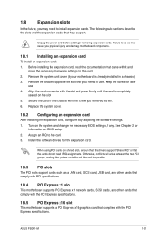
... complies with the slot and press firmly until the card is already installed in a chassis). 3. When using PCI cards on the slot. 5. ASUS P5G41-M 1-21 Install the software drivers for information on the system and change the necessary BIOS settings, if any. Otherwise, conflicts will arise between the... such as a LAN card, SCSI card, USB card, and other cards that comply with PCI specifications. 1.8.4 PCI Express x1 slot This motherboard supports PCI Express x1 network cards, SCSI cards, and other cards that comply with the PCI Express specifications. 1.8.5 PCI Express x16 slot This...
... complies with the slot and press firmly until the card is already installed in a chassis). 3. When using PCI cards on the slot. 5. ASUS P5G41-M 1-21 Install the software drivers for information on the system and change the necessary BIOS settings, if any. Otherwise, conflicts will arise between the... such as a LAN card, SCSI card, USB card, and other cards that comply with PCI specifications. 1.8.4 PCI Express x1 slot This motherboard supports PCI Express x1 network cards, SCSI cards, and other cards that comply with the PCI Express specifications. 1.8.5 PCI Express x16 slot This...
User Manual
Page 36
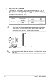
...device Two devices Drive jumper setting Cable-Select or Master Cable-Select Master Slave Mode of the following modes to configure your device. PRI_IDE PIN1 P5G41-M P5G41-M IDE connector NOTE:Orient the red markings on the Ultra DMA cable connector. Connect the blue connector to PIN 1. Master Slave Master Slave ... Gray Black or gray • Pin 20 on the IDE connector is removed to match the covered hole on the IDE ribbon cable to the motherboard's IDE connector, then select one of device(s) - If any device jumper is for Ultra DMA 100/66/33 IDE devices. There are three ...
...device Two devices Drive jumper setting Cable-Select or Master Cable-Select Master Slave Mode of the following modes to configure your device. PRI_IDE PIN1 P5G41-M P5G41-M IDE connector NOTE:Orient the red markings on the Ultra DMA cable connector. Connect the blue connector to PIN 1. Master Slave Master Slave ... Gray Black or gray • Pin 20 on the IDE connector is removed to match the covered hole on the IDE ribbon cable to the motherboard's IDE connector, then select one of device(s) - If any device jumper is for Ultra DMA 100/66/33 IDE devices. There are three ...


