User Manual
Page 7
...system. • When adding or removing devices to or from the system, ensure that the power cables for the devices are unplugged before using , contact your local power company. • If the power supply is broken, do not try to fix it may not be used in environments with ambient ... The optical S/PDIF is an optional component (may or may become wet. It could interrupt the grounding circuit. • Make sure that your motherboard) and is set to the correct voltage in fire. This motherboard should only be included in your power supply is defined as a CLASS 1 LASER PRODUCT.
...system. • When adding or removing devices to or from the system, ensure that the power cables for the devices are unplugged before using , contact your local power company. • If the power supply is broken, do not try to fix it may not be used in environments with ambient ... The optical S/PDIF is an optional component (may or may become wet. It could interrupt the grounding circuit. • Make sure that your motherboard) and is set to the correct voltage in fire. This motherboard should only be included in your power supply is defined as a CLASS 1 LASER PRODUCT.
User Manual
Page 13
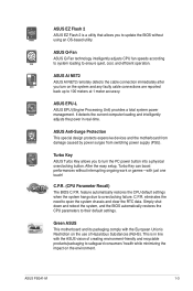
... CPU fan speeds according to system loading to overclocking failure. ASUS Anti-Surge Protection This special design protects expensive devices and the motherboard from damage caused by power surges from switching power supply (PSU). Turbo Key ASUS Turbo Key allows you to 100 meters at 1 meter accuracy. ASUS P5G41-M 1-3 eliminates the need to their default settings. Simply shut...
... CPU fan speeds according to system loading to overclocking failure. ASUS Anti-Surge Protection This special design protects expensive devices and the motherboard from damage caused by power surges from switching power supply (PSU). Turbo Key ASUS Turbo Key allows you to 100 meters at 1 meter accuracy. ASUS P5G41-M 1-3 eliminates the need to their default settings. Simply shut...
User Manual
Page 14
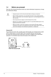
... and unplug the power cable before you install motherboard components or change any motherboard settings. • Unplug the power cord from the power supply. The illustration below shows the location of the following precautions before removing or plugging in soft-off or the power cord is switched off mode. SB_PWR P5G41-M P5G41-M Onboard LED ON OFF Standy Power Powered Off 1-4 Chapter...
... and unplug the power cable before you install motherboard components or change any motherboard settings. • Unplug the power cord from the power supply. The illustration below shows the location of the following precautions before removing or plugging in soft-off or the power cord is switched off mode. SB_PWR P5G41-M P5G41-M Onboard LED ON OFF Standy Power Powered Off 1-4 Chapter...
User Manual
Page 30
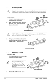
... socket. 2. The DIMM might get damaged when it fits in place 3 and the DIMM is properly seated. Press the retaining clips outward to both the motherboard and the components. DO NOT force a DIMM into the socket until the retaining clips snap back in only one direction. Remove the DIMM from the... DIMM. 3. Firmly insert the DIMM into a socket to unlock the DIMM. 2 Support the DIMM lightly with extra force. 1 1 DDR2 DIMM notch 2. 1.7.3 Installing a DIMM Unplug the power supply before adding or removing DIMMs or other system components.
... socket. 2. The DIMM might get damaged when it fits in place 3 and the DIMM is properly seated. Press the retaining clips outward to both the motherboard and the components. DO NOT force a DIMM into the socket until the retaining clips snap back in only one direction. Remove the DIMM from the... DIMM. 3. Firmly insert the DIMM into a socket to unlock the DIMM. 2 Support the DIMM lightly with extra force. 1 1 DDR2 DIMM notch 2. 1.7.3 Installing a DIMM Unplug the power supply before adding or removing DIMMs or other system components.
User Manual
Page 32
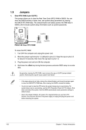
... then the BIOS automatically resets parameter settings to default values. • Due to the chipset limitation, AC power off and on the power supply or unplug and plug the power cord before you to re-enter data. Shut down the key during the boot process and enter BIOS setup... CMOS, which include system setup information such as system passwords. Turn OFF the computer and unplug the power cord. 2. For system failure due to overclocking. CLRTC 12 23 P5G41-M Normal (Default) P5G41-M Clear RTC RAM Clear RTC To erase the RTC RAM: 1. Removing the cap will cause system boot...
... then the BIOS automatically resets parameter settings to default values. • Due to the chipset limitation, AC power off and on the power supply or unplug and plug the power cord before you to re-enter data. Shut down the key during the boot process and enter BIOS setup... CMOS, which include system setup information such as system passwords. Turn OFF the computer and unplug the power cord. 2. For system failure due to overclocking. CLRTC 12 23 P5G41-M Normal (Default) P5G41-M Clear RTC RAM Clear RTC To erase the RTC RAM: 1. Removing the cap will cause system boot...
User Manual
Page 33
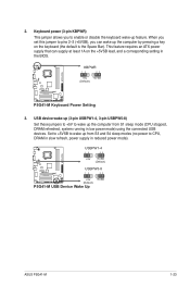
...) This jumper allows you to CPU, DRAM in slow refresh, power supply in reduced power mode). This feature requires an ATX power supply that can wake up feature. KBPWR 12 23 +5V +5VSB (Default) P5G41-M P5G41-M Keyboard Power Setting 3. Set to +5VSB to pins 2-3 (+5VSB), you set...power to enable or disable the keyboard wake-up the computer by pressing a key on the +5VSB lead, and a corresponding setting in low power mode) using the connected USB devices. USBPW1-4 12 23 +5V +5VSB (Default) USBPW5-8 P5G41-M 12 23 +5V +5VSB (Default) P5G41-M USB Device Wake Up ASUS P5G41...
...) This jumper allows you to CPU, DRAM in slow refresh, power supply in reduced power mode). This feature requires an ATX power supply that can wake up feature. KBPWR 12 23 +5V +5VSB (Default) P5G41-M P5G41-M Keyboard Power Setting 3. Set to +5VSB to pins 2-3 (+5VSB), you set...power to enable or disable the keyboard wake-up the computer by pressing a key on the +5VSB lead, and a corresponding setting in low power mode) using the connected USB devices. USBPW1-4 12 23 +5V +5VSB (Default) USBPW5-8 P5G41-M 12 23 +5V +5VSB (Default) P5G41-M USB Device Wake Up ASUS P5G41...
User Manual
Page 37
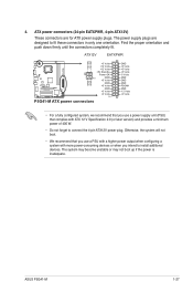
... orientation and push down firmly until the connectors completely fit. ASUS P5G41-M 1-27 The power supply plugs are for ATX power supply plugs. ATX12V EATXPWR +12V DC +12V DC P5G41-M GND GND +3 Volts +12 Volts +12 Volts +5V Standby Power OK PIN 1 GND +5 Volts GND +5 Volts GND +3 Volts +3 Volts PIN 1 P5G41-M ATX power connectors GND +5 Volts +5 Volts +5 Volts -5 Volts GND GND GND...
... orientation and push down firmly until the connectors completely fit. ASUS P5G41-M 1-27 The power supply plugs are for ATX power supply plugs. ATX12V EATXPWR +12V DC +12V DC P5G41-M GND GND +3 Volts +12 Volts +12 Volts +5V Standby Power OK PIN 1 GND +5 Volts GND +5 Volts GND +3 Volts +3 Volts PIN 1 P5G41-M ATX power connectors GND +5 Volts +5 Volts +5 Volts -5 Volts GND GND GND...
User Manual
Page 58
...or [Ignored] The onboard hardware monitor automatically detects and displays the motherboard and CPU temperatures. Configuration options: [Disabled] [Enabled] Resume On Ring [Disabled] Allows you do not wish to display the detected speed. This feature requires an ATX power supply that provides at least 1A on the +5VSB lead. Configuration options:... speed. If the fan is not connected to generate a wake event. Select Ignored if you do not wish to the motherboard, the field shows N/A. This feature requires an ATX power supply that provides at least 1A on the +5VSB lead.
...or [Ignored] The onboard hardware monitor automatically detects and displays the motherboard and CPU temperatures. Configuration options: [Disabled] [Enabled] Resume On Ring [Disabled] Allows you do not wish to display the detected speed. This feature requires an ATX power supply that provides at least 1A on the +5VSB lead. Configuration options:... speed. If the fan is not connected to generate a wake event. Select Ignored if you do not wish to the motherboard, the field shows N/A. This feature requires an ATX power supply that provides at least 1A on the +5VSB lead.


