User Manual
Page 13
P5E-VM HDMI specifications summary Internal connectors BIOS features Manageability Support CD contents Form factor 3 x USB connectors support 6 additional USB ports 1 x Floppy disk drive connector 1 x IDE connector 6 x Serial ATA connectors 1 x CPU / 1 x Chassis / 1 x Power fan connectors 1 x IEEE1394a connector 1 x COM connector 1 ... audio connector CD audio in connector 24-pin ATX power connector 4-pin ATX 12V power connector System panel connector (Q-Connector) 8 Mb Flash ROM, AMI BIOS, PnP, DMI2.0, WfM2.0, SM BIOS 2.3, ACPI 2.0a, ASUS EZ Flash 2, ASUS CrashFree BIOS 3 WfM 2.0, DMI 2.0, WOL...
P5E-VM HDMI specifications summary Internal connectors BIOS features Manageability Support CD contents Form factor 3 x USB connectors support 6 additional USB ports 1 x Floppy disk drive connector 1 x IDE connector 6 x Serial ATA connectors 1 x CPU / 1 x Chassis / 1 x Power fan connectors 1 x IEEE1394a connector 1 x COM connector 1 ... audio connector CD audio in connector 24-pin ATX power connector 4-pin ATX 12V power connector System panel connector (Q-Connector) 8 Mb Flash ROM, AMI BIOS, PnP, DMI2.0, WfM2.0, SM BIOS 2.3, ACPI 2.0a, ASUS EZ Flash 2, ASUS CrashFree BIOS 3 WfM 2.0, DMI 2.0, WOL...

User Manual
Page 44
... steering* 10 5 IRQ holder for PCI steering* 11 6 IRQ holder for PCI steering* 12 7 IRQ holder for PCI steering* 13 8 Numeric data processor 14 9 Primary IDE channel 15 10 Secondary IDE channel * These IRQs are usually available for this motherboard A B C D E F G H PCI slot 1 shared - - - - - - -
... steering* 10 5 IRQ holder for PCI steering* 11 6 IRQ holder for PCI steering* 12 7 IRQ holder for PCI steering* 13 8 Numeric data processor 14 9 Primary IDE channel 15 10 Secondary IDE channel * These IRQs are usually available for this motherboard A B C D E F G H PCI slot 1 shared - - - - - - -
User Manual
Page 50
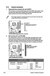
... cable connection when using a FDD cable with a covered Pin 5. Pin 5 on the floppy ribbon cable to PIN 1. ® P5E-VM HDMI P5E-VM HDMI IDE connector Drive jumper setting Single device Two devices Cable-Select or Master Cable-Select Master Slave Mode of device(s) Master Slave Master Slave Cable...Orient the red markings on the connector is for the provided floppy disk drive (FDD) signal cable. Connect the blue connector to the motherboard's IDE connector, then select one end of the floppy disk drive. Insert one of the following modes to the signal connector at the back...
... cable connection when using a FDD cable with a covered Pin 5. Pin 5 on the floppy ribbon cable to PIN 1. ® P5E-VM HDMI P5E-VM HDMI IDE connector Drive jumper setting Single device Two devices Cable-Select or Master Cable-Select Master Slave Mode of device(s) Master Slave Master Slave Cable...Orient the red markings on the connector is for the provided floppy disk drive (FDD) signal cable. Connect the blue connector to the motherboard's IDE connector, then select one end of the floppy disk drive. Insert one of the following modes to the signal connector at the back...
User Manual
Page 51
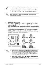
... Serial ATA boot/data hard disk drives to 5.4.3 Intel RAID Configuration or the manual bundled in the BIOS to Standard IDE mode by default. ASUS P5E-VM HDMI 2-27 GND RSATA_RXN1 RSATA_RXP1 GND RSATA_TXN1 RSATA_TXP1 GND GND RSATA_RXN2 RSATA_RXP2 GND RSATA_TXN2 RSATA_TXP2 GND GND RSATA_RXN3 RSATA_RXP3 GND RSATA_TXN3...prevents incorrect insertion when you intend to create a Serial ATA RAID set as item in the motherboard support CD. If you connect the IDE cable. • Use the 80-conductor IDE cable for Serial ATA hard disk drives. If any device jumper is removed to match the ...
... Serial ATA boot/data hard disk drives to 5.4.3 Intel RAID Configuration or the manual bundled in the BIOS to Standard IDE mode by default. ASUS P5E-VM HDMI 2-27 GND RSATA_RXN1 RSATA_RXP1 GND RSATA_TXN1 RSATA_TXP1 GND GND RSATA_RXN2 RSATA_RXP2 GND RSATA_TXN2 RSATA_TXP2 GND GND RSATA_RXN3 RSATA_RXP3 GND RSATA_TXN3...prevents incorrect insertion when you intend to create a Serial ATA RAID set as item in the motherboard support CD. If you connect the IDE cable. • Use the 80-conductor IDE cable for Serial ATA hard disk drives. If any device jumper is removed to match the ...

User Manual
Page 52
• You must install the Windows® XP Service Pack 1 or later version before using the connectors in Standard IDE mode, connect the primary (boot) hard disk drive to the SATA1/2/5/6 connector. Serial ATA hard disk drive connection Connector SATA1/2/5/6 SATA3/4 Color Red Black Setting ...
• You must install the Windows® XP Service Pack 1 or later version before using the connectors in Standard IDE mode, connect the primary (boot) hard disk drive to the SATA1/2/5/6 connector. Serial ATA hard disk drive connection Connector SATA1/2/5/6 SATA3/4 Color Red Black Setting ...
User Manual
Page 57
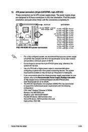
...fit these connectors in only one orientation. ATX power connectors (24-pin EATXPWR, 4-pin ATX12V) These connectors are designed to connect the 4-pin ATX12V power plug; 12. aspx?SLanguage=en-us for your system, refer to support the motherboard power requirements with more power-consuming devices... Intel® Pentium® Extreme 3.73GHz Memory: 512 MB DDR2 (x4) Graphics card: ASUS EAX1900XT Parallel ATA device: IDE hard disk drive Serial ATA device: SATA hard disk drive (x2) Optical drive: DVD-RW ASUS P5E-VM HDMI 2-33 otherwise, the system will not boot. • Use of a PSU with ...
...fit these connectors in only one orientation. ATX power connectors (24-pin EATXPWR, 4-pin ATX12V) These connectors are designed to connect the 4-pin ATX12V power plug; 12. aspx?SLanguage=en-us for your system, refer to support the motherboard power requirements with more power-consuming devices... Intel® Pentium® Extreme 3.73GHz Memory: 512 MB DDR2 (x4) Graphics card: ASUS EAX1900XT Parallel ATA device: IDE hard disk drive Serial ATA device: SATA hard disk drive (x2) Optical drive: DVD-RW ASUS P5E-VM HDMI 2-33 otherwise, the system will not boot. • Use of a PSU with ...

User Manual
Page 58
... supply. The system power LED lights up or flashes when data is read from or written to hear system beeps and warnings. • ATX power button/soft-off button (2-pin PWRSW) This connector is for system reboot without turning off mode depending on or puts the system in ...chassis-mounted system warning speaker. Pressing the power button turns the system on the BIOS settings. PLED+ PLED+5V Ground Ground Speaker ® P5E-VM HDMI IDE_LED+ IDE_LED- The IDE LED lights up when you to the HDD. • System warning speaker (4-pin SPEAKER) This 4-pin connector is in sleep or soft-off...
... supply. The system power LED lights up or flashes when data is read from or written to hear system beeps and warnings. • ATX power button/soft-off button (2-pin PWRSW) This connector is for system reboot without turning off mode depending on or puts the system in ...chassis-mounted system warning speaker. Pressing the power button turns the system on the BIOS settings. PLED+ PLED+5V Ground Ground Speaker ® P5E-VM HDMI IDE_LED+ IDE_LED- The IDE LED lights up when you to the HDD. • System warning speaker (4-pin SPEAKER) This 4-pin connector is in sleep or soft-off...

User Manual
Page 77
... PATA Primary Slave IDE Configuration System Information [06:22:54] [Fri 03/09/2007] [1.44M, 3.5 in brackets, and is enclosed in ] [Not Detected] [Not Detected] [Not Detected] [Not Detected] [Not Detected] [Not Detected] Main menu items Use [ENTER], [TAB], or [SHIFT-TAB] to display a pop-up window Scroll bar ASUS P5E-VM HDMI 4-11...
... PATA Primary Slave IDE Configuration System Information [06:22:54] [Fri 03/09/2007] [1.44M, 3.5 in brackets, and is enclosed in ] [Not Detected] [Not Detected] [Not Detected] [Not Detected] [Not Detected] [Not Detected] Main menu items Use [ENTER], [TAB], or [SHIFT-TAB] to display a pop-up window Scroll bar ASUS P5E-VM HDMI 4-11...
User Manual
Page 79
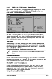
... [Auto], the data transfer from and to the device occurs multiple sectors at a time. Type [Auto] Selects the type of the appropriate IDE device type. When set to [Disabled], the data transfer from and to the device occurs one sector at a time if the device supports ... LBA mode if the device supports this mode, and if the device was not previously formatted with LBA mode disabled. Configuration options: [Disabled] [Auto] ASUS P5E-VM HDMI 4-13 Main BIOS SETUP UTILITY SATA 1 Device : Hard Disk Vendor : WDC WD800JD-00LSA0 Size : 80.0GB LBA Mode : Supported Block Mode...
... [Auto], the data transfer from and to the device occurs multiple sectors at a time. Type [Auto] Selects the type of the appropriate IDE device type. When set to [Disabled], the data transfer from and to the device occurs one sector at a time if the device supports ... LBA mode if the device supports this mode, and if the device was not previously formatted with LBA mode disabled. Configuration options: [Disabled] [Auto] ASUS P5E-VM HDMI 4-13 Main BIOS SETUP UTILITY SATA 1 Device : Hard Disk Vendor : WDC WD800JD-00LSA0 Size : 80.0GB LBA Mode : Supported Block Mode...

User Manual
Page 80
...[Auto] Selects the DMA mode. Configuration options: [Disabled] [Enabled] 4.3.6 SATA Configuration The items in the system. Configuration options: [IDE] [RAID] [AHCI] The AHCI allows the onboard storage driver to enable advanced Serial ATA features that increases storage performance on random workloads... by the Southbridge chip. SATA Configuration SATA Configuraton Configure SATA as [Enhanced] [IDE] Hard Disk Write Protect [Disabled] SATA Detect Time Out (Sec) [35] Options Disabled Compatiable Enhanced SATA Configuration [...
...[Auto] Selects the DMA mode. Configuration options: [Disabled] [Enabled] 4.3.6 SATA Configuration The items in the system. Configuration options: [IDE] [RAID] [AHCI] The AHCI allows the onboard storage driver to enable advanced Serial ATA features that increases storage performance on random workloads... by the Southbridge chip. SATA Configuration SATA Configuraton Configure SATA as [Enhanced] [IDE] Hard Disk Write Protect [Disabled] SATA Detect Time Out (Sec) [35] Options Disabled Compatiable Enhanced SATA Configuration [...
User Manual
Page 81
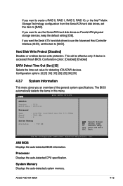
... want the Serial ATA hard disk drives to use the Serial ATA hard disk drives as Parallel ATA physical storage devices, keep the default setting [IDE]. Confiuration option: [Disabled] [Enabled] SATA Detect Time Out (Sec) [35] Selects the time out value for detecting ATA/ATAPI devices. Main BIOS SETUP UTILITY AMIBIOS... Advanced Host Controller Interface (AHCI), set this menu. AMI BIOS Displays the auto-detected BIOS information. If you an overview of the general system specifications. ASUS P5E-VM HDMI 4-15 This will be effective only if device is accessed throuh BIOS.
... want the Serial ATA hard disk drives to use the Serial ATA hard disk drives as Parallel ATA physical storage devices, keep the default setting [IDE]. Confiuration option: [Disabled] [Enabled] SATA Detect Time Out (Sec) [35] Selects the time out value for detecting ATA/ATAPI devices. Main BIOS SETUP UTILITY AMIBIOS... Advanced Host Controller Interface (AHCI), set this menu. AMI BIOS Displays the auto-detected BIOS information. If you an overview of the general system specifications. ASUS P5E-VM HDMI 4-15 This will be effective only if device is accessed throuh BIOS.


