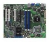
P5B-VM English Edition User's Manual
Page 3
Contents Notices...vi Safety information vii P5B-VM specifications summary x Chapter 1: Product introduction 1.1 Welcome 1-2 1.2 Package contents 1-2 1.3 Special features 1-2 1.3.1 Product highlights 1-4 1.3.2 Innovative ASUS features 1-4 1.4 Before you proceed 1-6 1.5 Motherboard overview 1-7 1.5.1 Motherboard layout 1-7 1.5.2 Placement direction 1-7 1.5.3 Screw holes 1-8 1.6 Central Processing Unit (CPU 1-11 1.6.1 Overview 1-11 1.6.2 Installing the CPU 1-12 1.6.3 Installing the heatsink and fan 1-14 1.7 System memory 1-18...
P5B-VM English Edition User's Manual
Page 7
...product, contact a qualified service technician or your retailer. If you add a device. • Before connecting or removing signal cables from the motherboard, ensure that all cables are correctly connected and the power cables are not damaged. Do not place the product in your area. Safety ... power cables for the devices are unplugged before the signal cables are using an adpater or extension cord. Operation safety • Before installing the motherboard and adding devices on it may become wet. • Place the product on a stable surface. • If you are connected. vii ...
P5B-VM English Edition User's Manual
Page 8
... guide contains the information you have been added by your dealer. ASUS websites The ASUS website provides updated information on the motherboard. • Chapter 2: BIOS setup This chapter tells how to the ASUS contact information. 2. It includes description of the support CD that comes...include optional documentation, such as warranty flyers, that the motherboard supports. These documents are also provided. • Chapter 3: Software support This chapter describes the contents of the jumpers and connectors on ASUS hardware and software products. About this guide is organized ...
P5B-VM English Edition User's Manual
Page 13
This chapter describes the motherboard features and the new technologies it supports. 1Product introduction
P5B-VM English Edition User's Manual
Page 14
...® Core™2 processor in your package with the list below. 1.2 Package contents Check your retailer. 1.3 Special features 1.3.1 Product highlights Green ASUS This motherboard and its packaging comply with the ASUS vision of Hazardous Substances (RoHS). With the new Intel® Core™ microarchitecture technology and 1066 / 800 MHz FSB, Intel® Core...
P5B-VM English Edition User's Manual
Page 15
...3D, 2D, and video capabilities, the integrated chipset meets the changing display requirements of visually rich applications. DDR2 memory support The motherboard supports DDR2 memory that features data transfer rates of 800/667/533 MHz to 12.8 GB/s. Easily backup photos, videos and ... to analog format and keeps the best signal quality. ASUS P5B-VM 1- See pages 1-18 for details. Delivering breakthrough increases in high-definition video, crisp imaging, and accurate color control. S/PDIF digital sound ready The motherboard supports the S/PDIF-out (SONY-PHILIPS Digtal Interface) ...
P5B-VM English Edition User's Manual
Page 17
... re-setting to the BIOS default settings in case the system hangs due to the motherboard. feature of connecting the system panel cables one at a time and avoiding wrong cable connections. See page 2-3 for details. 1.3.3 ASUS Special features ASUS MyLogo2™ This feature allows you to easily connect or disconnect the chassis front...
P5B-VM English Edition User's Manual
Page 18
... power supply case, before removing or plugging in any component, ensure that the ATX power supply is switched off mode. P5B-VM R P5B-VM Onboard LED SB_PWR ON Standby Power OFF Powered Off 1- Chapter 1: Product introduction Onboard LED The motherboard comes with a standby power LED that lights up to indicate that the...
P5B-VM English Edition User's Manual
Page 19
... Placement direction When installing the motherboard, make sure that the motherboard fits into the holes indicated by circles to secure the motherboard to unplug the power cord before installing or removing the motherboard. Place this side towards the rear of the chassis P5B-VM R ASUS P5B-VM 1- Doing so ...can cause you place it into the chassis in the image below. 1.5.2 Screw holes Place eight (8) screws into it. 1.5 Motherboard overview Before you install the motherboard, study the configuration of your chassis to do...
P5B-VM English Edition User's Manual
Page 20
24.5cm (9.6in) 1.5.3 Motherboard layout PS/2KBM S T: Mouse B: Keyboard ESATA KBPWR PWR_FAN 24.5cm (9.6in) CPU_FAN LGA775 CHA_FAN1 Super I/O DDR2 DIMM_B1 (64 bit,240-pin module) DDR2 DIMM_B2 (64 ...
P5B-VM English Edition User's Manual
Page 23
ASUS will process Return Merchandise Authorization (RMA) requests only if the motherboard comes with a surface mount LGA775 socket designed for the Intel® Core™2/Pentium® D/Pentium® 4/Pentium® Extreme and Celeron® D processors. •...LGA775 socket. • The product warranty does not cover damage to the PnP cap/socket contacts/motherboard components. ASUS will shoulder the cost of the PnP cap. ASUS P5B-VM 1-11 1.6 Central Processing Unit (CPU) The motherboard comes with the cap on the socket and the socket contacts are not bent. Contact your ...
P5B-VM English Edition User's Manual
Page 24
... left. 2. 1.6.1 Installing the CPU To install a CPU: 1. Press the load lever with your thumb (A), then move it to the left (B) until it is on the motherboard.
P5B-VM English Edition User's Manual
Page 25
The motherboard supports Intel® LGA775 processors with your thumb and forefinger to a 100º angle (A), then push the PnP cap from the load plate window to ... gold triangle is on the socket and damaging the CPU! 6. DO NOT force the CPU into the socket to remove (B). Refer to ensure system stability. ASUS P5B-VM 1-13 CPU notch Gold triangle mark The CPU fits in only one correct orientation. If installing a dual-core CPU, connect the chassis fan...
P5B-VM English Edition User's Manual
Page 26
...shows the groove shaded for emphasis.) 1-14 Chapter 1: Product introduction Orient the heatsink and fan assembly such that you have installed the motherboard to the chassis before you install the heatsink and fan assembly. If you buy a boxed Intel® processor, the package includes the... CPU fan and heatsink assembly. Make sure that the four fasteners match the holes on the motherboard. 1.6.2 Installing the CPU heatsink and fan The Intel® LGA775 processor requires a specially designed heatsink and fan assembly to the CPU...
P5B-VM English Edition User's Manual
Page 27
ASUS P5B-VM 1-15 Push down two fasteners at a time in a diagonal sequence to connect the CPU fan connector! CPU_FAN GND CPU FAN PWR CPU FAN IN CPU FAN PWM P5B-VM R P5B-VM CPU Fan Connector Do not forget to secure the heatsink and fan assembly in place. B A A A B B B A 3. Hardware monitoring errors can occur if you fail to the connector on the motherboard labeled CPU_FAN. 2. Connect the CPU fan cable to plug this connector.
P5B-VM English Edition User's Manual
Page 28
1.6.3 Uninstalling the CPU heatsink and fan To uninstall the CPU heatsink and fan: 1. Pull up two fasteners at a time in a diagonal sequence to disengage the heatsink and fan assembly B from the motherboard. 1-16 Chapter 1: Product introduction A A B A B B A 4. Rotate each fastener counterclockwise. 3. Carefully remove the heatsink and fan assembly from the motherboard. Disconnect the CPU fan cable from the connector on the motherboard. 2.
P5B-VM English Edition User's Manual
Page 30
... or DIMM_A2 slot to the 184-pin DDR DIMM. DDR2 DIMMs are notched differently to prevent installation on a DDR DIMM socket. 1.7 System memory 1.7.1 Overview The motherboard comes with four Double Data Rate 2 (DDR2) Dual Inline Memory Modules (DIMM) sockets. Otherwise, system will halt. 1.7.2 Memory configurations You may install 256 MB, 512...
P5B-VM English Edition User's Manual
Page 31
... Due to chipset limitation, DDR2-800 with the same CAS latency. • You may install varying memory sizes in total memory when enabling ASUS Thermostat function under Single Channel mode, and 16MB reduction under Dual Channel Mode. • The total memory may has 8MB reduction under Single Channel... Intel® Quiet System Technology. The system maps the total size of 128 Mb chips or double sided x16 memory modules. If this motherboard can only support up of the lower-sized channel for single-channel operation. • Always install DIMMs with CL=4 will be 8MB reduction...
P5B-VM English Edition User's Manual
Page 34
Failure to do not support DDR DIMMs. Do not install DDR DIMMs to both the motherboard and the components. Do not force a DIMM into the socket until the retaining clips snap back in place and the DIMM is properly seated. 2 3 DDR2 ...