
User Guide
Page 4
... function 3-2 3.2.2 Using the dual function power switch 3-2 3.3 ASUS POST Reporter 3-3 3.3.1 Vocal POST messages 3-3 3.3.2 Winbond Voice Editor 3-5 Chapter 4: BIOS setup 4.1 Managing and updating your BIOS 4-1 4.1.1 Creating a bootable floppy disk 4-1 4.1.2 AFUDOS utility 4-2 4.1.3 ASUS CrashFree BIOS 2 utility 4-5 4.1.4 ASUS EZ Flash utility 4-7 4.1.5 ASUS Update utility 4-8 4.2 BIOS setup program 4-11 4.2.2 Menu bar 4-12 4.2.3 Navigation keys 4-12 4.2.1 BIOS menu screen 4-12 4.2.4 Menu items 4-13 4.2.5 Sub...
... function 3-2 3.2.2 Using the dual function power switch 3-2 3.3 ASUS POST Reporter 3-3 3.3.1 Vocal POST messages 3-3 3.3.2 Winbond Voice Editor 3-5 Chapter 4: BIOS setup 4.1 Managing and updating your BIOS 4-1 4.1.1 Creating a bootable floppy disk 4-1 4.1.2 AFUDOS utility 4-2 4.1.3 ASUS CrashFree BIOS 2 utility 4-5 4.1.4 ASUS EZ Flash utility 4-7 4.1.5 ASUS Update utility 4-8 4.2 BIOS setup program 4-11 4.2.2 Menu bar 4-12 4.2.3 Navigation keys 4-12 4.2.1 BIOS menu screen 4-12 4.2.4 Menu items 4-13 4.2.5 Sub...

User Guide
Page 8
viii ASUS websites The ASUS website provides updated information on the motherboard. • Chapter 3: Powering up This chapter describes the power up sequence, the vocal POST messages, and ways of shutting down the system. • Chapter 4: BIOS setup This chapter tells how to perform when installing system components.... package may include optional documentation, such as warranty flyers, that may have to change system settings through the BIOS Setup menus. How this guide This user guide contains the information you have been added by your dealer. Detailed descriptions of the...
viii ASUS websites The ASUS website provides updated information on the motherboard. • Chapter 3: Powering up This chapter describes the power up sequence, the vocal POST messages, and ways of shutting down the system. • Chapter 4: BIOS setup This chapter tells how to perform when installing system components.... package may include optional documentation, such as warranty flyers, that may have to change system settings through the BIOS Setup menus. How this guide This user guide contains the information you have been added by your dealer. Detailed descriptions of the...

User Guide
Page 11
P5AD2-E Premium specifications summary LAN IEEE 1394 Overclocking features Special features BIOS features Rear panel Internal connectors 2 x Marvell® 88E8053 PCI Express™ Gigabit LAN controller Supports Marvell® Virtual Cable Tester technology Supports POST Network-diagnostic program TI 1394b controller supports: - 2 x IEEE 1394b connectors - 1 x IEEE 1394a ports ASUS AI Overclocking ASUS NOS (Non-delay Overclocking...
P5AD2-E Premium specifications summary LAN IEEE 1394 Overclocking features Special features BIOS features Rear panel Internal connectors 2 x Marvell® 88E8053 PCI Express™ Gigabit LAN controller Supports Marvell® Virtual Cable Tester technology Supports POST Network-diagnostic program TI 1394b controller supports: - 2 x IEEE 1394b connectors - 1 x IEEE 1394a ports ASUS AI Overclocking ASUS NOS (Non-delay Overclocking...

User Guide
Page 19
... ASUS WiFi-g™ is a BIOS-based diagnostic tool that detects and reports Ethernet cable faults and shorts. AI NET2 AI NET2 is backward compatible with IEEE 802.11b devices. ASUS provides full software application support and a user-friendly wizard to the LAN (RJ-45) port. ASUS P5AD2-E Premium ...1-5 See pages 4-23 and 5-13 for details. AI NOS™ (Non-Delay Overclocking System) ASUS Non-delay Overclocking System™ (NOS) is a specially designed PCB installed under the...
... ASUS WiFi-g™ is a BIOS-based diagnostic tool that detects and reports Ethernet cable faults and shorts. AI NET2 AI NET2 is backward compatible with IEEE 802.11b devices. ASUS provides full software application support and a user-friendly wizard to the LAN (RJ-45) port. ASUS P5AD2-E Premium ...1-5 See pages 4-23 and 5-13 for details. AI NOS™ (Non-Delay Overclocking System) ASUS Non-delay Overclocking System™ (NOS) is a specially designed PCB installed under the...

User Guide
Page 20
...offers native DDR2-711/600 memory support to buy a replacement ROM chip. ASUS Multi-language BIOS The multi-language BIOS allows you to personalize and add style to restore the original BIOS data from the available options. The bundled Winbond Voice Editor software lets ... eliminates the need to ensure superior system performance. CrashFree BIOS 2 This feature allows you to ensure quiet, cool, and efficient operation. The localized BIOS menus allow easier and faster configuration. ASUS Q-Fan 2 technology The ASUS Q-Fan 2 technology smartly adjusts the fan speeds according to...
...offers native DDR2-711/600 memory support to buy a replacement ROM chip. ASUS Multi-language BIOS The multi-language BIOS allows you to personalize and add style to restore the original BIOS data from the available options. The bundled Winbond Voice Editor software lets ... eliminates the need to ensure superior system performance. CrashFree BIOS 2 This feature allows you to ensure quiet, cool, and efficient operation. The localized BIOS menus allow easier and faster configuration. ASUS Q-Fan 2 technology The ASUS Q-Fan 2 technology smartly adjusts the fan speeds according to...

User Guide
Page 40
... with it by adjusting the software settings. 1. Keep the screw for information on the next page for the expansion card. Refer to the table on BIOS setup. 2. 2.5 Expansion slots In the future, you intend to use . 4. See Chapter 4 for later use . Replace the system cover. 2.5.2 Configuring an ... system unstable and the card inoperable. Remove the system unit cover (if your motherboard is completely seated on the system and change the necessary BIOS settings, if any. Refer to the tables on shared slots, ensure that the drivers support "Share IRQ" or that they support. When ...
... with it by adjusting the software settings. 1. Keep the screw for information on the next page for the expansion card. Refer to the table on BIOS setup. 2. 2.5 Expansion slots In the future, you intend to use . 4. See Chapter 4 for later use . Replace the system cover. 2.5.2 Configuring an ... system unstable and the card inoperable. Remove the system unit cover (if your motherboard is completely seated on the system and change the necessary BIOS settings, if any. Refer to the tables on shared slots, ensure that the drivers support "Share IRQ" or that they support. When ...
User Guide
Page 43
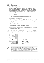
...6. For system failure due to pins 1-2. 4. To erase the RTC RAM: 1. Remove the onboard battery. 3. Hold down and reboot the system so the BIOS can clear the CMOS memory of date, time, and system setup parameters by erasing the CMOS RTC RAM data. Clear RTC RAM (CLRTC) This jumper... to pins 2-3. Move the jumper cap from pins 1-2 (default) to overclocking. Shut down the key during the boot process and enter BIOS setup to default values. ASUS P5AD2-E Premium 2-21 Except when clearing the RTC RAM, never remove the cap on pins 2-3 for about 5~10 seconds, then move the cap back...
...6. For system failure due to pins 1-2. 4. To erase the RTC RAM: 1. Remove the onboard battery. 3. Hold down and reboot the system so the BIOS can clear the CMOS memory of date, time, and system setup parameters by erasing the CMOS RTC RAM data. Clear RTC RAM (CLRTC) This jumper... to pins 2-3. Move the jumper cap from pins 1-2 (default) to overclocking. Shut down the key during the boot process and enter BIOS setup to default values. ASUS P5AD2-E Premium 2-21 Except when clearing the RTC RAM, never remove the cap on pins 2-3 for about 5~10 seconds, then move the cap back...

User Guide
Page 44
... +5VSB (Default) ® USBPW56 USBPW78 12 23 +5V P5AD2-E PREMIUM USB device wake-up (Default) +5VSB • The USB device wake-up the computer when you can connect to CPU, DRAM in slow refresh, power supply in the BIOS. Set this jumper to pins 2-3 (+5VSB) to wake up feature requires a power supply... NOT exceed the power supply capability (+5VSB) whether under normal condition or in low power mode) using the connected USB devices. KBPWR1 12 23 P5AD2-E PREMIUM +5V +5VSB (Default) ® P5AD2-E PREMIUM Keyboard power setting 2-22 Chapter 2: Hardware information
... +5VSB (Default) ® USBPW56 USBPW78 12 23 +5V P5AD2-E PREMIUM USB device wake-up (Default) +5VSB • The USB device wake-up the computer when you can connect to CPU, DRAM in slow refresh, power supply in the BIOS. Set this jumper to pins 2-3 (+5VSB) to wake up feature requires a power supply... NOT exceed the power supply capability (+5VSB) whether under normal condition or in low power mode) using the connected USB devices. KBPWR1 12 23 P5AD2-E PREMIUM +5V +5VSB (Default) ® P5AD2-E PREMIUM Keyboard power setting 2-22 Chapter 2: Hardware information

User Guide
Page 48
...Configuration" for details. 2-26 Chapter 2: Hardware information 3 . In I T E 8 2 1 2 F C o n t r o l l e r item in the BIOS to the hard disk drive documentation for details. PRI_RAID1 PIN 1 P5AD2-E PREMIUM RAID connectors • Before creating a RAID set the hard disk drives as boot/data hard disk drives or optical drives.... P5AD2-E PREMIUM SEC_RAID1 NOTE: Orient the red markings ® (usually zigzag) on how to four IDE hard disk drives that you can ...
...Configuration" for details. 2-26 Chapter 2: Hardware information 3 . In I T E 8 2 1 2 F C o n t r o l l e r item in the BIOS to the hard disk drive documentation for details. PRI_RAID1 PIN 1 P5AD2-E PREMIUM RAID connectors • Before creating a RAID set the hard disk drives as boot/data hard disk drives or optical drives.... P5AD2-E PREMIUM SEC_RAID1 NOTE: Orient the red markings ® (usually zigzag) on how to four IDE hard disk drives that you can ...
User Guide
Page 49
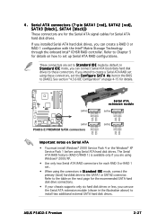
... intend to create a Serial ATA RAID set the C o n f i g u r e S A T A A s item in the illustration above) to [RAID]. ASUS P5AD2-E Premium 2-27 If you can create a RAID 0 or RAID 1 configuration with the Intel® Matrix Storage Technology through the onboard Intel® ICH6R RAID controller. Refer... Serial ATA boot/data hard disk drives to S t a n d a r d I D E mode, you can use the Serial ATA extension module (shown in the BIOS to install two additional external SATA hard disk drives. In S t a n d a r d I D E mode by default. These connectors are for the Serial ATA signal ...
... intend to create a Serial ATA RAID set the C o n f i g u r e S A T A A s item in the illustration above) to [RAID]. ASUS P5AD2-E Premium 2-27 If you can create a RAID 0 or RAID 1 configuration with the Intel® Matrix Storage Technology through the onboard Intel® ICH6R RAID controller. Refer... Serial ATA boot/data hard disk drives to S t a n d a r d I D E mode, you can use the Serial ATA extension module (shown in the BIOS to install two additional external SATA hard disk drives. In S t a n d a r d I D E mode by default. These connectors are for the Serial ATA signal ...

User Guide
Page 50
...BIOS setup during POST. • You can configure as a disk array through the onboard SATA RAID controller. See Chapter 5 for details on how to set using Serial ATA hard disks, make sure that you want to connect Serial ATA boot/data hard disk drives to Chapter 5 for details. P5AD2-E PREMIUM... GND RSATA_RXP2 RSATA_RXN2 GND GND RSATA_TXP3 RSATA_TXN3 GND RSATA_RXP3 RSATA_RXN3 GND GND RSATA_TXP4 RSATA_TXN4 GND RSATA_RXP4 RSATA_RXN4 GND ® SATA_RAID1 SATA_RAID2 SATA_RAID3 SATA_RAID4 P5AD2-E PREMIUM SATA RAID connectors • Before creating a RAID set the S i l i c o n I D M o d e by...
...BIOS setup during POST. • You can configure as a disk array through the onboard SATA RAID controller. See Chapter 5 for details on how to set using Serial ATA hard disks, make sure that you want to connect Serial ATA boot/data hard disk drives to Chapter 5 for details. P5AD2-E PREMIUM... GND RSATA_RXP2 RSATA_RXN2 GND GND RSATA_TXP3 RSATA_TXN3 GND RSATA_RXP3 RSATA_RXN3 GND GND RSATA_TXP4 RSATA_TXN4 GND RSATA_RXP4 RSATA_RXN4 GND ® SATA_RAID1 SATA_RAID2 SATA_RAID3 SATA_RAID4 P5AD2-E PREMIUM SATA RAID connectors • Before creating a RAID set the S i l i c o n I D M o d e by...

User Guide
Page 52
...+ GND NC USB+5V USB_P7USB_P7+ GND USB+5V USB_P5USB_P5+ GND USB56 1 P5AD2-E PREMIUM USB 2.0 connectors USB78 1 Never connect a 1 3 9 4 c a b l e to 480 Mbps connection speed. 8 . GND PRESENCE# SENSE1_RETUR SENSE2_RETUR P5AD2-E PREMIUM AGND NC NC NC ® AAFP MIC2 MICPWR Line out_R NC Line out_L... PORT1 L PORT1 R PORT2 R SENSE_SEND PORT2 L AC '97 audio pin definition P5AD2-E PREMIUM Analog front panel connector • It is set the F r o n t P a n e l S u p p o r t T y p e item in the BIOS Setup to avail of the system chassis. If you connect a high-definition front ...
...+ GND NC USB+5V USB_P7USB_P7+ GND USB+5V USB_P5USB_P5+ GND USB56 1 P5AD2-E PREMIUM USB 2.0 connectors USB78 1 Never connect a 1 3 9 4 c a b l e to 480 Mbps connection speed. 8 . GND PRESENCE# SENSE1_RETUR SENSE2_RETUR P5AD2-E PREMIUM AGND NC NC NC ® AAFP MIC2 MICPWR Line out_R NC Line out_L... PORT1 L PORT1 R PORT2 R SENSE_SEND PORT2 L AC '97 audio pin definition P5AD2-E PREMIUM Analog front panel connector • It is set the F r o n t P a n e l S u p p o r t T y p e item in the BIOS Setup to avail of the system chassis. If you connect a high-definition front ...

User Guide
Page 57
...puts the system in sleep mode. • Hard disk drive activity LED (Red 2-pin IDE_LED) This 2-pin connector is for easy connection. ASUS P5AD2-E Premium 2-35 Refer to the HDD. • System warning speaker (Orange 4-pin SPEAKER) This 4-pin connector is for the system power LED. ...- Connect the HDD Activity LED cable to this connector. Pressing the power button turns the system on the BIOS settings. PWR Ground Reset Ground IDE_LED RESET PWRSW P5AD2-E PREMIUM System panel connector The sytem panel connector is for the chassis-mounted reset button for the system power button...
...puts the system in sleep mode. • Hard disk drive activity LED (Red 2-pin IDE_LED) This 2-pin connector is for easy connection. ASUS P5AD2-E Premium 2-35 Refer to the HDD. • System warning speaker (Orange 4-pin SPEAKER) This 4-pin connector is for the system power LED. ...- Connect the HDD Activity LED cable to this connector. Pressing the power button turns the system on the BIOS settings. PWR Ground Reset Ground IDE_LED RESET PWRSW P5AD2-E PREMIUM System panel connector The sytem panel connector is for the chassis-mounted reset button for the system power button...

User Guide
Page 61
... on the power, the system may light up or switch between orange and green after the system LED turns on the devices in Chapter 4. ASUS P5AD2-E Premium 3-1 If your retailer for the first time 1. Be sure that is equipped with "green" standards or if it has a "power standby"... in the following order: a. Connect the power cord to a power outlet that all the connections, replace the system case cover. 2. AMI BIOS beep codes Beep Description One beep Two continuous beeps followed by two short beeps Two continuous beeps followed by four short beeps Error Keyboard controller...
... on the power, the system may light up or switch between orange and green after the system LED turns on the devices in Chapter 4. ASUS P5AD2-E Premium 3-1 If your retailer for the first time 1. Be sure that is equipped with "green" standards or if it has a "power standby"... in the following order: a. Connect the power cord to a power outlet that all the connections, replace the system case cover. 2. AMI BIOS beep codes Beep Description One beep Two continuous beeps followed by two short beeps Two continuous beeps followed by four short beeps Error Keyboard controller...

User Guide
Page 62
.... 3.2.2 Using the dual function power switch While the system is selected, then click the O K button to soft-off mode, depending on the BIOS setting. If you are using Windows® 2000: 1. 3.2 Powering off the computer 3.2.1 Using the OS shut down the computer. 3. Refer to ... h u t D o w n option button is ON, pressing the power switch for less than four seconds lets the system enter the soft-off mode regardless of the BIOS setting. Pressing the power switch for details. 3-2 Chapter 3: Powering up Click the T u r n O f f button to section "4.5 Power Menu" in Chapter 4 for...
.... 3.2.2 Using the dual function power switch While the system is selected, then click the O K button to soft-off mode, depending on the BIOS setting. If you are using Windows® 2000: 1. 3.2 Powering off the computer 3.2.1 Using the OS shut down the computer. 3. Refer to ... h u t D o w n option button is ON, pressing the power switch for less than four seconds lets the system enter the soft-off mode regardless of the BIOS setting. Pressing the power switch for details. 3-2 Chapter 3: Powering up Click the T u r n O f f button to section "4.5 Power Menu" in Chapter 4 for...

User Guide
Page 63
...Winbond Voice Editor software that alerts you will hear the specific cause of system events and boot status. See the ASUS contact information on the motherboard. In case of a boot failure, you of the problem. These POST messages are... • Make sure that your graphics card is not defective. • Check your CPU overclocking settings in the BIOS setup and restore the default CPU parameters. • Check if your keyboard is a list of the IDE connectors on... your DIMMs are not defective. • Refer to section "2.4 System memory" for assistance. ASUS P5AD2-E Premium 3-3
...Winbond Voice Editor software that alerts you will hear the specific cause of system events and boot status. See the ASUS contact information on the motherboard. In case of a boot failure, you of the problem. These POST messages are... • Make sure that your graphics card is not defective. • Check your CPU overclocking settings in the BIOS setup and restore the default CPU parameters. • Check if your keyboard is a list of the IDE connectors on... your DIMMs are not defective. • Refer to section "2.4 System memory" for assistance. ASUS P5AD2-E Premium 3-3

User Guide
Page 64
See the "ASUS contact information" on after you apply power to the system. • Make sure that your CPU fan supports the fan speed detection function. • Check ... on the inside front cover of range Computer now booting from operating system Action • Check if the CPU fan is not defective. • Call ASUS technical support for details. 3-4 Chapter 3: Powering up See section 4.4.8 for assistance. POST Message CPU temperature too high CPU fan failed CPU voltage out of this...
See the "ASUS contact information" on after you apply power to the system. • Make sure that your CPU fan supports the fan speed detection function. • Check ... on the inside front cover of range Computer now booting from operating system Action • Check if the CPU fan is not defective. • Call ASUS technical support for details. 3-4 Chapter 3: Powering up See section 4.4.8 for assistance. POST Message CPU temperature too high CPU fan failed CPU voltage out of this...

User Guide
Page 69
Detailed descriptions of the BIOS parameters are also provided. 4 BIOS setup This chapter tells how to change the system settings through the BIOS Setup menus.
Detailed descriptions of the BIOS parameters are also provided. 4 BIOS setup This chapter tells how to change the system settings through the BIOS Setup menus.

User Guide
Page 70
Chapter summary 4 4.1 Managing and updating your BIOS 4-1 4.2 BIOS setup program 4-11 4.3 Main menu 4-14 4.4 Advanced menu 4-19 4.5 Power menu 4-33 4.6 Boot menu 4-38 4.7 Exit menu 4-43 ASUS P5AD2-E Premium
Chapter summary 4 4.1 Managing and updating your BIOS 4-1 4.2 BIOS setup program 4-11 4.3 Main menu 4-14 4.4 Advanced menu 4-19 4.5 Power menu 4-33 4.6 Boot menu 4-38 4.7 Exit menu 4-43 ASUS P5AD2-E Premium

User Guide
Page 71
...; XP environment a. A S U S U p d a t e (Updates the BIOS in the future. c. W i n d o w s® X P u s e r s : Select C r e a t e a n M S - Save a copy of the following utilities allow you need to restore the BIOS in Windows® environment.) Refer to the corresponding sections for details on these utilities. D O S s t a r t u p d i s k from the format options field, then click S t a r t. ASUS P5AD2-E Premium 4-1 4.1 Managing and updating your BIOS The following to create...
...; XP environment a. A S U S U p d a t e (Updates the BIOS in the future. c. W i n d o w s® X P u s e r s : Select C r e a t e a n M S - Save a copy of the following utilities allow you need to restore the BIOS in Windows® environment.) Refer to the corresponding sections for details on these utilities. D O S s t a r t u p d i s k from the format options field, then click S t a r t. ASUS P5AD2-E Premium 4-1 4.1 Managing and updating your BIOS The following to create...


