Motherboard DIY Troubleshooting Guide
Page 46
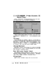
Change Option F1 General Help F10 Save and Exit ESC Exit 2-12 Primary IDE Master Device : Hard Disk Vendor : ST320413A Size : 20.0GB LBA Mode : Supported Block Mode : 16 Sectors PIO Mode : 4 Async DMA : MultiWord DMA-2 Ultra DMA : Ultra DMA-5 SMART Monitoring: Supported Type LBA/Large Mode Block (Multi-sector Transfer) PIO Mode DMA Mode Smart Monitoring 32Bit Data Transfer [Auto] [Auto] [Auto] [Auto] [Auto] [Auto] [Disabled] Select the type of device connected to the system. Select Screen Select Item +-
Change Option F1 General Help F10 Save and Exit ESC Exit 2-12 Primary IDE Master Device : Hard Disk Vendor : ST320413A Size : 20.0GB LBA Mode : Supported Block Mode : 16 Sectors PIO Mode : 4 Async DMA : MultiWord DMA-2 Ultra DMA : Ultra DMA-5 SMART Monitoring: Supported Type LBA/Large Mode Block (Multi-sector Transfer) PIO Mode DMA Mode Smart Monitoring 32Bit Data Transfer [Auto] [Auto] [Auto] [Auto] [Auto] [Auto] [Disabled] Select the type of device connected to the system. Select Screen Select Item +-
Motherboard DIY Troubleshooting Guide
Page 49
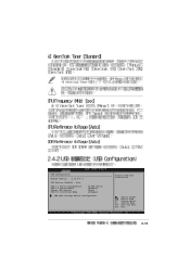
Change Option F1 General Help F10 Save and Exit ESC Exit 2-15 USB Configuration Module Version : 2.22.4-5.3 USB Devices Enabled : None USB 1.1 Ports Configuration USB 2.0 Ports Enable Legacy USB Support USB 2.0 Controller Mode [8 USB Ports] [Enabled] [Auto] [HiSpeed] USB Mass Storage Device Configuration Enables USB host controllers. Select Screen Select Item +-
Change Option F1 General Help F10 Save and Exit ESC Exit 2-15 USB Configuration Module Version : 2.22.4-5.3 USB Devices Enabled : None USB 1.1 Ports Configuration USB 2.0 Ports Enable Legacy USB Support USB 2.0 Controller Mode [8 USB Ports] [Enabled] [Auto] [HiSpeed] USB Mass Storage Device Configuration Enables USB host controllers. Select Screen Select Item +-

Motherboard DIY Troubleshooting Guide
Page 52
******** DRAM Timing ******** Configure SDRAM Timing by SPD SDRAM Frequency SDRAM Burst Length SDRAM Command Rate Primary Graphics Adapter V-Link 8X Supported AGP Mode Graphics Aperture Size [Enabled] [Auto] [4QW] [2T] [AGP] [Enabled] Auto [64MB] Select Screen Select Item +- Change Option F1 General Help F10 Save and Exit ESC Exit 2-18
******** DRAM Timing ******** Configure SDRAM Timing by SPD SDRAM Frequency SDRAM Burst Length SDRAM Command Rate Primary Graphics Adapter V-Link 8X Supported AGP Mode Graphics Aperture Size [Enabled] [Auto] [4QW] [2T] [AGP] [Enabled] Auto [64MB] Select Screen Select Item +- Change Option F1 General Help F10 Save and Exit ESC Exit 2-18

Motherboard DIY Troubleshooting Guide
Page 56
Select Screen Select Item Enter Go to Sub-screen F1 General Help F10 Save and Exit ESC Exit 2-22 Suspend Mode Repost Video on S3 Resume ACPI 2.0 Support ACPI APIC Support APM Configuration Hardware Monitor [S1 (POS) only] [No] [No] [Enabled] Configure CPU.
Select Screen Select Item Enter Go to Sub-screen F1 General Help F10 Save and Exit ESC Exit 2-22 Suspend Mode Repost Video on S3 Resume ACPI 2.0 Support ACPI APIC Support APM Configuration Hardware Monitor [S1 (POS) only] [No] [No] [Enabled] Configure CPU.
Motherboard DIY Troubleshooting Guide
Page 61
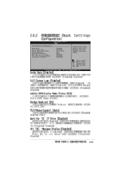
Change Option F1 General Help F10 Save and Exit ESC Exit 2-27 Boot Settings Configuration Quick Boot Full Screen Logo Add On ROM Display Mode Bootup Num-Lock PS/2 Mouse Support Wait for 'F1' If Error Hit 'DEL' Message Display Interrupt 19 Capture [Enabled] [Enabled] [Force BIOS] [On] [Auto] [Enabled] [Enabled]\ [Disabled] Allows BIOS to boot the system. Select Screen Select Item +- This will decrease the time needed to skip certain tests while booting.
Change Option F1 General Help F10 Save and Exit ESC Exit 2-27 Boot Settings Configuration Quick Boot Full Screen Logo Add On ROM Display Mode Bootup Num-Lock PS/2 Mouse Support Wait for 'F1' If Error Hit 'DEL' Message Display Interrupt 19 Capture [Enabled] [Enabled] [Force BIOS] [On] [Auto] [Enabled] [Enabled]\ [Disabled] Allows BIOS to boot the system. Select Screen Select Item +- This will decrease the time needed to skip certain tests while booting.
P4V8X-X User Manual
Page 4
... 2-17 2.4.5 Onboard Devices Configuration 2-20 2.4.6 PCI PnP 2-21 2.5 Power menu 2-22 2.5.1 2.5.2 2.5.3 2.5.4 2.5.5 2.5.6 Suspend Mode [Auto 2-22 Repost Video on S3 Resume [No 2-22 ACPI 2.0 Support [No 2-22 ACPI APIC Support [Enabled 2-23 APM Configuration 2-23 Hardware Monitor 2-24 2.6 Boot menu 2-26 2.6.1 Boot Device Priority 2-26 2.6.2 Boot Settings Configuration 2-27 2.6.3 Security 2-28 2.7 Exit menu...
... 2-17 2.4.5 Onboard Devices Configuration 2-20 2.4.6 PCI PnP 2-21 2.5 Power menu 2-22 2.5.1 2.5.2 2.5.3 2.5.4 2.5.5 2.5.6 Suspend Mode [Auto 2-22 Repost Video on S3 Resume [No 2-22 ACPI 2.0 Support [No 2-22 ACPI APIC Support [Enabled 2-23 APM Configuration 2-23 Hardware Monitor 2-24 2.6 Boot menu 2-26 2.6.1 Boot Device Priority 2-26 2.6.2 Boot Settings Configuration 2-27 2.6.3 Security 2-28 2.7 Exit menu...
P4V8X-X User Manual
Page 9
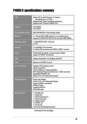
P4V8X-X specifications summary CPU Chipset Front Side Bus (FSB) Memory Expansion slots Storage Audio LAN USB AI Overclocking Special features Back panel I/O Socket 478 for Intel® Pentium® 4 / Celeron with speeds up to 3.2 GHz+ Supports Intel® Hyper-Threading technology Supports...adjustable SFS (Stepless Frequency Selection) at 1 MHz increment Adjustable FSB/DDR ratio ASUS C.P.R. (CPU Parameter Recall) Power Loss Restart ASUS C.P.R. (CPU Parameter Recall) support S/PDIF out interface ASUS EZ Flash CrashFree BIOS 2 ASUS MyLogo2 1 x Parallel port 1 x Serial port 1 x PS/2 keyboard ...
P4V8X-X specifications summary CPU Chipset Front Side Bus (FSB) Memory Expansion slots Storage Audio LAN USB AI Overclocking Special features Back panel I/O Socket 478 for Intel® Pentium® 4 / Celeron with speeds up to 3.2 GHz+ Supports Intel® Hyper-Threading technology Supports...adjustable SFS (Stepless Frequency Selection) at 1 MHz increment Adjustable FSB/DDR ratio ASUS C.P.R. (CPU Parameter Recall) Power Loss Restart ASUS C.P.R. (CPU Parameter Recall) support S/PDIF out interface ASUS EZ Flash CrashFree BIOS 2 ASUS MyLogo2 1 x Parallel port 1 x Serial port 1 x PS/2 keyboard ...
P4V8X-X User Manual
Page 10
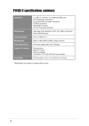
x P4V8X-X specifications summary Internal I/O BIOS features Industry standard Manageability Power Requirement Support CD contents Form Factor 2 x USB 2.0 connector for 4 additional USB ports CPU/Chassis fan connectors 20-pin/4-pin ATX 12V power connectors CD/AUX connectors Game/MIDI connector 10-1 pin front panel connector 4Mb Flash ROM, AMI BIOS, ACPI, PnP, DMI2.0, ASUS EZ...
x P4V8X-X specifications summary Internal I/O BIOS features Industry standard Manageability Power Requirement Support CD contents Form Factor 2 x USB 2.0 connector for 4 additional USB ports CPU/Chassis fan connectors 20-pin/4-pin ATX 12V power connectors CD/AUX connectors Game/MIDI connector 10-1 pin front panel connector 4Mb Flash ROM, AMI BIOS, ACPI, PnP, DMI2.0, ASUS EZ...
P4V8X-X User Manual
Page 12
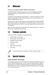
...items is your retailer. 1.3 Special features Latest processor technology The motherboard supports the Intel® Pentium® 4 processor with support for an effective desktop platform solution. The ASUS P4V8X-X motherboard delivers a host of ASUS quality motherboards! The CPU features the Intel Hyper-Threading Technology and a...frequencies with 512KB L2 cache and an 800*/533/400 MHz system bus. Before you for the following items. ASUS P4V8X-X motherboard ASUS P4V8X-X series support CD UltraDMA 133/100/66 cable Floppy disk cable I/O shield Bag of extra jumper caps User Guide If any ...
...items is your retailer. 1.3 Special features Latest processor technology The motherboard supports the Intel® Pentium® 4 processor with support for an effective desktop platform solution. The ASUS P4V8X-X motherboard delivers a host of ASUS quality motherboards! The CPU features the Intel Hyper-Threading Technology and a...frequencies with 512KB L2 cache and an 800*/533/400 MHz system bus. Before you for the following items. ASUS P4V8X-X motherboard ASUS P4V8X-X series support CD UltraDMA 133/100/66 cable Floppy disk cable I/O shield Bag of extra jumper caps User Guide If any ...
P4V8X-X User Manual
Page 13
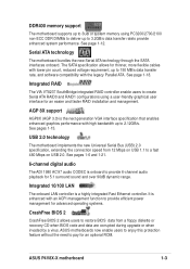
...or when invaded by a virus. See page 1-18. DDR400 memory support The motherboard supports up to 3GB of system memory using a user-friendly graphical user interface for an optional ROM. ASUS motherboards now enable users to enjoy this protection feature without the need to... pay for an easier and faster RAID installation and management. AGP 8X support AGP8X (AGP 3.0) is enhanced with high bandwidth up to 3.2GB/s data transfer rateto provide enhanced system performance. ASUS P4V8X-X motherboard 1-3 The SATA specification allows for 5.1 surround sound and over 90dB dynamic...
...or when invaded by a virus. See page 1-18. DDR400 memory support The motherboard supports up to 3GB of system memory using a user-friendly graphical user interface for an optional ROM. ASUS motherboards now enable users to enjoy this protection feature without the need to... pay for an easier and faster RAID installation and management. AGP 8X support AGP8X (AGP 3.0) is enhanced with high bandwidth up to 3.2GB/s data transfer rateto provide enhanced system performance. ASUS P4V8X-X motherboard 1-3 The SATA specification allows for 5.1 surround sound and over 90dB dynamic...
P4V8X-X User Manual
Page 15
...floppy disk cable. 11 Standby power LED. This 4Mb firmware contains the programmable BIOS program. 13 Super I /O functionality. These dual-channel bus master IDE connectors support Ultra DMA133/100/66, PIO Modes 3 & 4 IDE devices. This Low Pin Count (LPC) interface provides the commonly used Super I /O controller. This...controller. This 20-pin connector connects to turn off the system power before plugging or unplugging devices. 12 Flash ROM. The chipset supports a highperformance floppy disk controller for 3D graphical applications. 8 SATA connectors. ASUS P4V8X-X motherboard 1-5
...floppy disk cable. 11 Standby power LED. This 4Mb firmware contains the programmable BIOS program. 13 Super I /O functionality. These dual-channel bus master IDE connectors support Ultra DMA133/100/66, PIO Modes 3 & 4 IDE devices. This Low Pin Count (LPC) interface provides the commonly used Super I /O controller. This...controller. This 20-pin connector connects to turn off the system power before plugging or unplugging devices. 12 Flash ROM. The chipset supports a highperformance floppy disk controller for 3D graphical applications. 8 SATA connectors. ASUS P4V8X-X motherboard 1-5

P4V8X-X User Manual
Page 16
...pin Universal Serial Bus (USB) ports are available for a PS/2 keyboard. 1-6 Chapter 1: Product introduction 15 PCI slots. These 32-bit PCI 2.2 expansion slots support bus master PCI cards like SCSI or LAN cards with 133MB/s maximum throughput. 16 LAN controller. This jack connects to a Local Area Network (LAN) through... a network hub. 20 Line In jack. This Realtek RTL8201BL LAN PHY supports 10BASE-T/ 100BASE-TX networking. 17 PS/2 mouse port. This Line Out (lime) jack connects a headphone or a speaker.
...pin Universal Serial Bus (USB) ports are available for a PS/2 keyboard. 1-6 Chapter 1: Product introduction 15 PCI slots. These 32-bit PCI 2.2 expansion slots support bus master PCI cards like SCSI or LAN cards with 133MB/s maximum throughput. 16 LAN controller. This jack connects to a Local Area Network (LAN) through... a network hub. 20 Line In jack. This Realtek RTL8201BL LAN PHY supports 10BASE-T/ 100BASE-TX networking. 17 PS/2 mouse port. This Line Out (lime) jack connects a headphone or a speaker.
P4V8X-X User Manual
Page 20
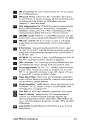
...Hyper-Threading Technology, visit www.intel.com/ info/hyperthreading. Reboot the computer. 1-10 Chapter 1: Product introduction This motherboard supports Intel Pentium 4 CPUs with an 800MHz FSB CPU, enable the CPU Compatible Mode item in the BIOS to lower FSB frequency....CPU! Notes on one corner. See section "2.4.1 JumperFree configuration" for details. • Incorrect installation of the CPU socket. ® P4V8X-X P4V8X-X Socket 478 Gold Arrow • If the system becomes unstable when overclocking with Hyper-Threading Technology. 2. Hyper-Threading Technology is recommended...
...Hyper-Threading Technology, visit www.intel.com/ info/hyperthreading. Reboot the computer. 1-10 Chapter 1: Product introduction This motherboard supports Intel Pentium 4 CPUs with an 800MHz FSB CPU, enable the CPU Compatible Mode item in the BIOS to lower FSB frequency....CPU! Notes on one corner. See section "2.4.1 JumperFree configuration" for details. • Incorrect installation of the CPU socket. ® P4V8X-X P4V8X-X Socket 478 Gold Arrow • If the system becomes unstable when overclocking with Hyper-Threading Technology. 2. Hyper-Threading Technology is recommended...
P4V8X-X User Manual
Page 22
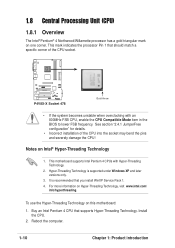
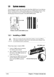
... snap back in place and the DIMM is properly Unlocked Retaining Clip seated. 1-12 Chapter 1: Product introduction DIMM1 DIMM2 DIMM3 104 Pins 80 Pins ® P4V8X-X P4V8X-X 184-Pin DDR DIMM Sockets 1.9.1 Installing a DIMM Make sure to install a DIMM. Align a DIMM on the socket such that the notch on the DIMM matches.... The following figure shows the location of the DDR DIMM sockets. Unlock a DIMM socket by pressing the retaining clips outward. 2. DDR DIMM notch 1. These sockets support up to both the motherboard and the components.
... snap back in place and the DIMM is properly Unlocked Retaining Clip seated. 1-12 Chapter 1: Product introduction DIMM1 DIMM2 DIMM3 104 Pins 80 Pins ® P4V8X-X P4V8X-X 184-Pin DDR DIMM Sockets 1.9.1 Installing a DIMM Make sure to install a DIMM. Align a DIMM on the socket such that the notch on the DIMM matches.... The following figure shows the location of the DDR DIMM sockets. Unlock a DIMM socket by pressing the retaining clips outward. 2. DDR DIMM notch 1. These sockets support up to both the motherboard and the components.
P4V8X-X User Manual
Page 24
.../Real Time Clock 9* 4 ACPI Mode when used PCI slot 4 shared - - - Onboard USB controller HC2 - shared - - Onboard USB 2.0 controller - - shared - Onboard audio - - NOTE: The AGP slot supports only 1.5V and 0.8V AGP cards. 2. PCI slot 3 - - - Install the drivers and/or software applications for BIOS information. 3. Onboard USB controller HC1 shared - - - Onboard USB...
.../Real Time Clock 9* 4 ACPI Mode when used PCI slot 4 shared - - - Onboard USB controller HC2 - shared - - Onboard USB 2.0 controller - - shared - Onboard audio - - NOTE: The AGP slot supports only 1.5V and 0.8V AGP cards. 2. PCI slot 3 - - - Install the drivers and/or software applications for BIOS information. 3. Onboard USB controller HC1 shared - - - Onboard USB...
P4V8X-X User Manual
Page 25
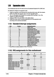
... has an Accelerated Graphics Port (AGP) slot that they fit the AGP slot on this motherboard. When you ask for 1.5v P4V8X-X Accelerated Graphics Port (AGP) ASUS P4V8X-X motherboard 1-15 The slots support PCI cards such as a LAN card, SCSI card, USB card, and other cards that you buy an AGP card, make sure...
... has an Accelerated Graphics Port (AGP) slot that they fit the AGP slot on this motherboard. When you ask for 1.5v P4V8X-X Accelerated Graphics Port (AGP) ASUS P4V8X-X motherboard 1-15 The slots support PCI cards such as a LAN card, SCSI card, USB card, and other cards that you buy an AGP card, make sure...
P4V8X-X User Manual
Page 27
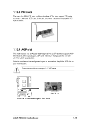
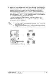
... are for the internal USB header that can connect to support this feature. 2. The USBPW12 and USBPW34 jumpers are for each USB port. 2. USBPW12 USBPW34 12 23 +5V (Default) +5VSB ® P4V8X-X USBPW78 USBPW56 12 23 +5V P4V8X-X USB Device Wake Up (Default) +5VSB ASUS P4V8X-X motherboard 1-17 This feature requires a power supply that you...
... are for the internal USB header that can connect to support this feature. 2. The USBPW12 and USBPW34 jumpers are for each USB port. 2. USBPW12 USBPW34 12 23 +5V (Default) +5VSB ® P4V8X-X USBPW78 USBPW56 12 23 +5V P4V8X-X USB Device Wake Up (Default) +5VSB ASUS P4V8X-X motherboard 1-17 This feature requires a power supply that you...
P4V8X-X User Manual
Page 28
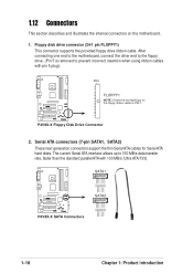
... provided floppy drive ribbon cable. Serial ATA connectors (7-pin SATA1, SATA2) These next generation connectors support the thin Serial ATA cables for Serial ATA hard disks. After connecting one end to the motherboard, connect the other end ...when using ribbon cables with 133 MB/s (Ultra ATA/133). SATA1 GND RSATA_RXP1 RSATA_RXN1 GND RSATA_TXN1 RSATA_TXP1 GND ® P4V8X-X SATA2 GND RSATA_RXP2 RSATA_RXN2 GND RSATA_TXN2 RSATA_TXP2 GND P4V8X-X SATA Connectors 1-18 Chapter 1: Product introduction 1.12 Connectors This section describes and illustrates the internal connectors on the ...
... provided floppy drive ribbon cable. Serial ATA connectors (7-pin SATA1, SATA2) These next generation connectors support the thin Serial ATA cables for Serial ATA hard disks. After connecting one end to the motherboard, connect the other end ...when using ribbon cables with 133 MB/s (Ultra ATA/133). SATA1 GND RSATA_RXP1 RSATA_RXN1 GND RSATA_TXN1 RSATA_TXP1 GND ® P4V8X-X SATA2 GND RSATA_RXP2 RSATA_RXN2 GND RSATA_TXN2 RSATA_TXP2 GND P4V8X-X SATA Connectors 1-18 Chapter 1: Product introduction 1.12 Connectors This section describes and illustrates the internal connectors on the ...
P4V8X-X User Manual
Page 29
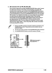
...the primary IDE connector and another UltraDMA100/66/33 cable. For UltraDMA100/66 IDE devices, use the 80-conductor IDE cable. ® P4V8X-X P4V8X-X IDE Connectors SEC_IDE1 PRI_IDE1 NOTE: Orient the red markings (usually zigzag) on each IDE connector is intentional. 3. IDE connectors (40... BIOS supports specific device bootup. one for the secondary IDE connector. 1. 3. You may configure two hard disks to the secondary IDE connector. It is recommended that you must configure the second drive as a slave device by setting its jumper accordingly. PIN 1 ASUS P4V8X-X motherboard...
...the primary IDE connector and another UltraDMA100/66/33 cable. For UltraDMA100/66 IDE devices, use the 80-conductor IDE cable. ® P4V8X-X P4V8X-X IDE Connectors SEC_IDE1 PRI_IDE1 NOTE: Orient the red markings (usually zigzag) on each IDE connector is intentional. 3. IDE connectors (40... BIOS supports specific device bootup. one for the secondary IDE connector. 1. 3. You may configure two hard disks to the secondary IDE connector. It is recommended that you must configure the second drive as a slave device by setting its jumper accordingly. PIN 1 ASUS P4V8X-X motherboard...
P4V8X-X User Manual
Page 30
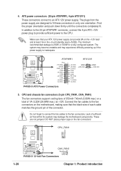
...power supply. DO NOT place jumper caps on the fan connectors! CPU and chassis fan connectors (3-pin CPU_FAN1, CHA_FAN1) The fan connectors support cooling fans of 350mA~740mA (8.88W max.) or a total of 1A~2.22A (26.64W max.) at least 1A on the motherboard...to fit these connectors in only one orientation. CPU_FAN1 GND +12V Rotation ® P4V8X-X CHA_FAN1 Rotation +12V GND P4V8X-X 12-Volt Fan Connectors 1-20 Chapter 1: Product introduction The minimum recommended wattage is inadequate. ® P4V8X-X ATXPWR1 ATX12V1 Pin 1 +12.0VDC +5VSB PWR_OK COM +5.0VDC COM +5.0VDC ...
...power supply. DO NOT place jumper caps on the fan connectors! CPU and chassis fan connectors (3-pin CPU_FAN1, CHA_FAN1) The fan connectors support cooling fans of 350mA~740mA (8.88W max.) or a total of 1A~2.22A (26.64W max.) at least 1A on the motherboard...to fit these connectors in only one orientation. CPU_FAN1 GND +12V Rotation ® P4V8X-X CHA_FAN1 Rotation +12V GND P4V8X-X 12-Volt Fan Connectors 1-20 Chapter 1: Product introduction The minimum recommended wattage is inadequate. ® P4V8X-X ATXPWR1 ATX12V1 Pin 1 +12.0VDC +5VSB PWR_OK COM +5.0VDC COM +5.0VDC ...


