P4P800-E Deluxe User's manual for English Version E1867
Page 4
... Reporter 3-3 3.3.1 Vocal POST messages 3-3 3.3.2 Winbond Voice Editor 3-5 Chapter 4: BIOS setup 4.1 Managing and updating your BIOS 4-1 4.1.1 Creating a bootable floppy disk 4-1 4.1.2 Using AFUDOS to update the BIOS 4-2 4.1.3 Using AFUDOS to copy BIOS from PC 4-3 4.1.4 Using ASUS EZ Flash to update the BIOS 4-4 4.1.5 Recovering the BIOS with CrashFree BIOS 2 ....... 4-5 4.1.6 ASUS Update 4-7 4.2 BIOS Setup program 4-9 4.2.1 BIOS menu screen 4-10 4.2.2 Menu bar 4-10 4.2.3 Navigation keys 4-10...
... Reporter 3-3 3.3.1 Vocal POST messages 3-3 3.3.2 Winbond Voice Editor 3-5 Chapter 4: BIOS setup 4.1 Managing and updating your BIOS 4-1 4.1.1 Creating a bootable floppy disk 4-1 4.1.2 Using AFUDOS to update the BIOS 4-2 4.1.3 Using AFUDOS to copy BIOS from PC 4-3 4.1.4 Using ASUS EZ Flash to update the BIOS 4-4 4.1.5 Recovering the BIOS with CrashFree BIOS 2 ....... 4-5 4.1.6 ASUS Update 4-7 4.2 BIOS Setup program 4-9 4.2.1 BIOS menu screen 4-10 4.2.2 Menu bar 4-10 4.2.3 Navigation keys 4-10...
P4P800-E Deluxe User's manual for English Version E1867
Page 5
...menu 4-28 4.5.1 Suspend Mode [Auto 4-28 4.5.2 Repost Video on S3 Resume [No 4-28 4.5.3 ACPI 2.0 Support [No 4-28 4.5.4 ACPI APIC Support [Enabled 4-28 4.5.5 BIOS -> AML ACPI Table [Enabled 4-28 4.5.6 APM Configuration 4-29 4.5.7 Hardware Monitor 4-31 4.6 Boot menu 4-32 4.6.1 Boot Device Priority 4-33 4.6.2 Hard disk drives 4-33 ... 4-37 Chapter 5: Software support 5.1 Install an operating system 5-1 5.2 Support CD information 5-1 5.2.1 Running the support CD 5-1 5.2.2 Drivers menu 5-2 5.2.3 Utilities menu 5-3 5.2.4 ASUS Contact Information 5-4 5.2.5 Other information 5-5 v
...menu 4-28 4.5.1 Suspend Mode [Auto 4-28 4.5.2 Repost Video on S3 Resume [No 4-28 4.5.3 ACPI 2.0 Support [No 4-28 4.5.4 ACPI APIC Support [Enabled 4-28 4.5.5 BIOS -> AML ACPI Table [Enabled 4-28 4.5.6 APM Configuration 4-29 4.5.7 Hardware Monitor 4-31 4.6 Boot menu 4-32 4.6.1 Boot Device Priority 4-33 4.6.2 Hard disk drives 4-33 ... 4-37 Chapter 5: Software support 5.1 Install an operating system 5-1 5.2 Support CD information 5-1 5.2.1 Running the support CD 5-1 5.2.2 Drivers menu 5-2 5.2.3 Utilities menu 5-3 5.2.4 ASUS Contact Information 5-4 5.2.5 Other information 5-5 v
P4P800-E Deluxe User's manual for English Version E1867
Page 6
Contents 5.3 Software Information 5-7 5.3.1 ASUS MyLogo2 5-7 5.3.2 ASUS Instant Music 5-9 5.4 AI Net feature 5-12 5.5 Audio configurations 5-13 5.5.1 Sound Effect options 5-13 5.5.2 S/PDIF options 5-14 5.5.3 Speaker ...RAID 0 array (Performance 5-22 5.6.4 Creating a RAID 1 array (Security 5-23 5.6.5 Other FastBuild Utility Commands 5-25 5.7 Intel® RAID for Serial ATA configuration 5-27 5.7.1 BIOS Configuration 5-27 5.7.2 Installing Serial ATA (SATA) hard disks 5-27 5.7.3 Creating, Deleting, and Resetting RAID Sets ...... 5-28 5.7.4 Creating a RAID Volume 5-28 5.7.5 Deleting a ...
Contents 5.3 Software Information 5-7 5.3.1 ASUS MyLogo2 5-7 5.3.2 ASUS Instant Music 5-9 5.4 AI Net feature 5-12 5.5 Audio configurations 5-13 5.5.1 Sound Effect options 5-13 5.5.2 S/PDIF options 5-14 5.5.3 Speaker ...RAID 0 array (Performance 5-22 5.6.4 Creating a RAID 1 array (Security 5-23 5.6.5 Other FastBuild Utility Commands 5-25 5.7 Intel® RAID for Serial ATA configuration 5-27 5.7.1 BIOS Configuration 5-27 5.7.2 Installing Serial ATA (SATA) hard disks 5-27 5.7.3 Creating, Deleting, and Resetting RAID Sets ...... 5-28 5.7.4 Creating a RAID Volume 5-28 5.7.5 Deleting a ...
P4P800-E Deluxe User's manual for English Version E1867
Page 9
...are also provided. • Chapter 5: Software support This chapter describes the contents of the standard package. Detailed descriptions of the BIOS parameters are not part of the support CD that may include optional documentation, such as warranty flyers, that comes with the ... chapter describes the power up sequence, the vocal POST messages, and ways of the jumpers and connectors on ASUS hardware and software products. It includes description of shutting down the system. • Chapter 4: BIOS setup This chapter tells how to perform when installing system components.
...are also provided. • Chapter 5: Software support This chapter describes the contents of the standard package. Detailed descriptions of the BIOS parameters are not part of the support CD that may include optional documentation, such as warranty flyers, that comes with the ... chapter describes the power up sequence, the vocal POST messages, and ways of the jumpers and connectors on ASUS hardware and software products. It includes description of shutting down the system. • Chapter 4: BIOS setup This chapter tells how to perform when installing system components.

P4P800-E Deluxe User's manual for English Version E1867
Page 11
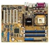
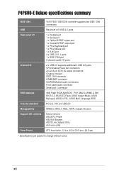
P4P800-E Deluxe specifications summary CPU Chipset Front Side Bus (FSB) Memory Expansion slots Storage AI Audio AI Net AI BIOS AI Overclocking Special features Socket 478 for Intel® Pentium® 4 / Celeron processors with speeds up to 3.2 GHz+ ...PDIF out interface support Marvell® 88E8001 Gigabit Ethernet controller Virtual Cable Tester (VCT) Technology support ASUS CrashFree BIOS2 ASUS Q-Fan Technology ASUS Post Reporter™ Intelligent CPU frequency tuner ASUS JumperFree CPU, Memory and AGP voltage adjustable SFS (Stepless Frequency Selection) from 100MHz up to 400MHz ...
P4P800-E Deluxe specifications summary CPU Chipset Front Side Bus (FSB) Memory Expansion slots Storage AI Audio AI Net AI BIOS AI Overclocking Special features Socket 478 for Intel® Pentium® 4 / Celeron processors with speeds up to 3.2 GHz+ ...PDIF out interface support Marvell® 88E8001 Gigabit Ethernet controller Virtual Cable Tester (VCT) Technology support ASUS CrashFree BIOS2 ASUS Q-Fan Technology ASUS Post Reporter™ Intelligent CPU frequency tuner ASUS JumperFree CPU, Memory and AGP voltage adjustable SFS (Stepless Frequency Selection) from 100MHz up to 400MHz ...
P4P800-E Deluxe User's manual for English Version E1867
Page 12
P4P800-E Deluxe specifications summary IEEE 1394 VIA VT6307 IEEE1394 controller supports two IEEE 1394 connectors USB Maximum of 8 USB 2.0 ports Rear panel I/O 1 x Parallel port 1 x Serial port ... 1394 connector GAME/MIDI connector CD/AUX/Modem audio connectors Front panel audio connector Serial port 2 connector BIOS features 4Mb Flash ROM, AMI BIOS, PnP, DMI2.0, WfM2.0, SM BIOS 2.3, ASUS EZ Flash, ASUS Instant Music, ASUS MyLogo2, ASUS C.P.R., ASUS Multi-Language BIOS Industry standard PCI 2.2, PCI 2.3, USB 2.0 Manageability WfM2.0, DMI 2.0, WOL, WOR, chassis intrusion Support ...
P4P800-E Deluxe specifications summary IEEE 1394 VIA VT6307 IEEE1394 controller supports two IEEE 1394 connectors USB Maximum of 8 USB 2.0 ports Rear panel I/O 1 x Parallel port 1 x Serial port ... 1394 connector GAME/MIDI connector CD/AUX/Modem audio connectors Front panel audio connector Serial port 2 connector BIOS features 4Mb Flash ROM, AMI BIOS, PnP, DMI2.0, WfM2.0, SM BIOS 2.3, ASUS EZ Flash, ASUS Instant Music, ASUS MyLogo2, ASUS C.P.R., ASUS Multi-Language BIOS Industry standard PCI 2.2, PCI 2.3, USB 2.0 Manageability WfM2.0, DMI 2.0, WOL, WOR, chassis intrusion Support ...

P4P800-E Deluxe User's manual for English Version E1867
Page 18
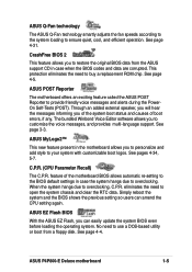
...multimedia systems. It also features intelligent detection of plugged peripherals into the audio ports and identifies any incompatible devices. AI BIOS solution The AI BIOS is a combination of three ASUS intelligent solutions: Q-Fan, POST Reporter, and CrashFree BIOS2. 1-4 Chapter 1: Product introduction See page 2-19. AI ... to set up to 30% (depending on Motherboard (LOM) applications. See page 4-17. 1.3.2 Unique ASUS features ASUS Wi-Fi slot The ASUS Wi-Fi slot is designed for the ASUS WiFi-b™ add-on card bundles the exclusive software Access Point (AP) to save the extra cost ...
...multimedia systems. It also features intelligent detection of plugged peripherals into the audio ports and identifies any incompatible devices. AI BIOS solution The AI BIOS is a combination of three ASUS intelligent solutions: Q-Fan, POST Reporter, and CrashFree BIOS2. 1-4 Chapter 1: Product introduction See page 2-19. AI ... to set up to 30% (depending on Motherboard (LOM) applications. See page 4-17. 1.3.2 Unique ASUS features ASUS Wi-Fi slot The ASUS Wi-Fi slot is designed for the ASUS WiFi-b™ add-on card bundles the exclusive software Access Point (AP) to save the extra cost ...
P4P800-E Deluxe User's manual for English Version E1867
Page 19
... multi-language support. The bundled Winbond Voice Editor software allows you to buy a replacement ROM chip. eliminates the need to restore the original BIOS data from a floppy disk. ASUS P4P800-E Deluxe motherboard 1-5 Through an added external speaker, you will hear the messages informing you of the system boot status and causes of the motherboard...
... multi-language support. The bundled Winbond Voice Editor software allows you to buy a replacement ROM chip. eliminates the need to restore the original BIOS data from a floppy disk. ASUS P4P800-E Deluxe motherboard 1-5 Through an added external speaker, you will hear the messages informing you of the system boot status and causes of the motherboard...
P4P800-E Deluxe User's manual for English Version E1867
Page 20
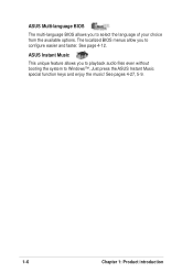
The localized BIOS menus allow you to playback audio files even without booting the system to Windows™. Just press the ASUS Instant Music special function keys and enjoy the music! See pages 4-27, 5-9. 1-6 Chapter 1: Product introduction ASUS Instant Music This unique feature allows you to select the language of your choice from the available options. See page 4-12. ASUS Multi-language BIOS The multi-language BIOS allows you to configure easier and faster.
The localized BIOS menus allow you to playback audio files even without booting the system to Windows™. Just press the ASUS Instant Music special function keys and enjoy the music! See pages 4-27, 5-9. 1-6 Chapter 1: Product introduction ASUS Instant Music This unique feature allows you to select the language of your choice from the available options. See page 4-12. ASUS Multi-language BIOS The multi-language BIOS allows you to configure easier and faster.
P4P800-E Deluxe User's manual for English Version E1867
Page 28
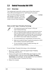
... installing a supported operating system. 5. For more information on Intel® Hyper-Threading Technology 1. Power up the system and enter BIOS Setup (see Chapter 4). This mark should match a specific corner on the socket to ensure system stability and performance. 3. Install the CPU. 2. To use the Hyper-.... Take note of the marked corner (with gold triangle) on this motherboard: 1. Hyper-Threading Technology is set to enable the Hyper-Threading Technology item in BIOS to ensure correct installation. Under Linux, use the Hyper-Threading Technology on the CPU.
... installing a supported operating system. 5. For more information on Intel® Hyper-Threading Technology 1. Power up the system and enter BIOS Setup (see Chapter 4). This mark should match a specific corner on the socket to ensure system stability and performance. 3. Install the CPU. 2. To use the Hyper-.... Take note of the marked corner (with gold triangle) on this motherboard: 1. Hyper-Threading Technology is set to enable the Hyper-Threading Technology item in BIOS to ensure correct installation. Under Linux, use the Hyper-Threading Technology on the CPU.
P4P800-E Deluxe User's manual for English Version E1867
Page 38
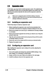
.... Turn on the slot. 5. Remove the system unit cover (if your motherboard is completely seated on the system and change the necessary BIOS settings, if any. Secure the card to install an expansion card. 1. Failure to do so may need to the tables on the next... by adjusting the software settings. 1. See Chapter 4 for the expansion card. 2-16 Chapter 2: Hardware information Install the software drivers for information on BIOS setup. 2. The motherboard has available PCI slots and an Accelerated Graphics Port (AGP) slot. Refer to install expansion cards. 2.5 Expansion slots In ...
.... Turn on the slot. 5. Remove the system unit cover (if your motherboard is completely seated on the system and change the necessary BIOS settings, if any. Secure the card to install an expansion card. 1. Failure to do so may need to the tables on the next... by adjusting the software settings. 1. See Chapter 4 for the expansion card. 2-16 Chapter 2: Hardware information Install the software drivers for information on BIOS setup. 2. The motherboard has available PCI slots and an Accelerated Graphics Port (AGP) slot. Refer to install expansion cards. 2.5 Expansion slots In ...
P4P800-E Deluxe User's manual for English Version E1867
Page 42
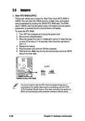
... the power cord. 2. Remove the onboard battery. 3. Plug the power cord and turn ON the computer. 6. Hold down and reboot the system so BIOS can clear the CMOS memory of date, time, and system setup parameters by the onboard button cell battery. Move the jumper from pins 1-2 (default) ...to pins 1-2. 4. Replace the battery. 5. Shut down the key during the boot process and enter BIOS setup to re-enter data. ® P4P800-E P4P800-E Clear RTC RAM CLRTC 12 Normal (Default) 23 Clear CMOS You do not need to clear the RTC when the system hangs...
... the power cord. 2. Remove the onboard battery. 3. Plug the power cord and turn ON the computer. 6. Hold down and reboot the system so BIOS can clear the CMOS memory of date, time, and system setup parameters by the onboard button cell battery. Move the jumper from pins 1-2 (default) ...to pins 1-2. 4. Replace the battery. 5. Shut down the key during the boot process and enter BIOS setup to re-enter data. ® P4P800-E P4P800-E Clear RTC RAM CLRTC 12 Normal (Default) 23 Clear CMOS You do not need to clear the RTC when the system hangs...
P4P800-E Deluxe User's manual for English Version E1867
Page 44
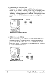
Set this jumper to pins 2-3 (+5VSB) if you wish to enable the SMBus 2.0 feature. ® P4P800-E P4P800-E SMB2.0 Support SMB20 12 23 Enable Disable (Default) 2-22 Chapter 2: Hardware information This feature requires an ATX power supply that comply with SMBus 2.0 ...-2 to wake up feature. SMB2.0 (two 3-pin SMB20) These jumpers allow you press a key on the +5VSB lead, and a corresponding setting in the BIOS. By default, these jumpers are set to pins 2-3 to enable or disable the SMBus 2.0 feature supported on the motherboard. Keyboard power (3-pin KBPWR) This jumper...
Set this jumper to pins 2-3 (+5VSB) if you wish to enable the SMBus 2.0 feature. ® P4P800-E P4P800-E SMB2.0 Support SMB20 12 23 Enable Disable (Default) 2-22 Chapter 2: Hardware information This feature requires an ATX power supply that comply with SMBus 2.0 ...-2 to wake up feature. SMB2.0 (two 3-pin SMB20) These jumpers allow you press a key on the +5VSB lead, and a corresponding setting in the BIOS. By default, these jumpers are set to pins 2-3 to enable or disable the SMBus 2.0 feature supported on the motherboard. Keyboard power (3-pin KBPWR) This jumper...
P4P800-E Deluxe User's manual for English Version E1867
Page 49
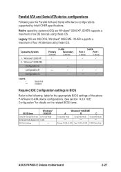
...A B C Compatible Mode - Compatible Mode - Windows® 98SE/ME Configuration A Configuration B Configuration C Legend: - P-ATA+S-ATA P-ATA Ports Only ASUS P4P800-E Deluxe motherboard 2-27 ICH5R supports a maximum of six (6) devices using these OS. Parallel ATA and Serial ATA device configurations Following are MS-DOS, Windows®... 98SE/ME. Required IDE Configuration settings in BIOS Refer to the following table for details on the related BIOS items. BIOS item Windows® 2000/XP Onboard IDE Operate Mode Enhanced Mode Enhanced ...
...A B C Compatible Mode - Compatible Mode - Windows® 98SE/ME Configuration A Configuration B Configuration C Legend: - P-ATA+S-ATA P-ATA Ports Only ASUS P4P800-E Deluxe motherboard 2-27 ICH5R supports a maximum of six (6) devices using these OS. Parallel ATA and Serial ATA device configurations Following are MS-DOS, Windows®... 98SE/ME. Required IDE Configuration settings in BIOS Refer to the following table for details on the related BIOS items. BIOS item Windows® 2000/XP Onboard IDE Operate Mode Enhanced Mode Enhanced ...
P4P800-E Deluxe User's manual for English Version E1867
Page 51
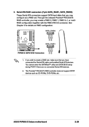
...set . 5. Through the onboard Promise® PDC20378 RAID controller, you have connected the Serial ATA cable and installed Serial ATA devices. ASUS P4P800-E Deluxe motherboard 2-29 If you may create a RAID 0, RAID 1, RAID 0+1, or multiRAID configuration together with the RAID ATA133 connector. You ...cannot enter the SATARaid™ utility and SATA BIOS setup during POST if there are no connected Serial ATA devices. 2. Serial ATA RAID connectors (7-pin SATA_RAID1, SATA_RAID2) These Serial ...
...set . 5. Through the onboard Promise® PDC20378 RAID controller, you have connected the Serial ATA cable and installed Serial ATA devices. ASUS P4P800-E Deluxe motherboard 2-29 If you may create a RAID 0, RAID 1, RAID 0+1, or multiRAID configuration together with the RAID ATA133 connector. You ...cannot enter the SATARaid™ utility and SATA BIOS setup during POST if there are no connected Serial ATA devices. 2. Serial ATA RAID connectors (7-pin SATA_RAID1, SATA_RAID2) These Serial ...
P4P800-E Deluxe User's manual for English Version E1867
Page 58
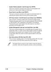
... save power and to light up. Pressing the power switch turns the system between ON and SLEEP, or ON and SOFT OFF, depending on the BIOS or OS settings. Take note of an IDE device cause this 2-pin connector. • Hard disk activity LED (Red 2-pin IDE_LED) This connector supplies power...
... save power and to light up. Pressing the power switch turns the system between ON and SLEEP, or ON and SOFT OFF, depending on the BIOS or OS settings. Take note of an IDE device cause this 2-pin connector. • Hard disk activity LED (Red 2-pin IDE_LED) This connector supplies power...
P4P800-E Deluxe User's manual for English Version E1867
Page 61
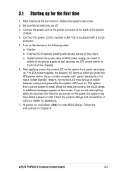
...the chassis). 6. While the tests are off. 3. Check the jumper settings and connections or call your monitor complies with a surge protector. 5. ASUS P4P800-E Deluxe motherboard 3-1 Connect the power cord to switch on the power supply as well as press the ATX power switch on the front of the system...within 30 seconds from the time you press the ATX power switch. 3.1 Starting up for assistance. 7. After making all switches are running, the BIOS beeps or additional messages appear on test. After applying power, the power LED on the chain) c. If your retailer for the first time 1....
...the chassis). 6. While the tests are off. 3. Check the jumper settings and connections or call your monitor complies with a surge protector. 5. ASUS P4P800-E Deluxe motherboard 3-1 Connect the power cord to switch on the power supply as well as press the ATX power switch on the front of the system...within 30 seconds from the time you press the ATX power switch. 3.1 Starting up for assistance. 7. After making all switches are running, the BIOS beeps or additional messages appear on test. After applying power, the power LED on the chain) c. If your retailer for the first time 1....
P4P800-E Deluxe User's manual for English Version E1867
Page 62
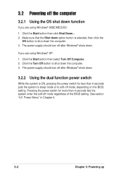
... the computer 3.2.1 Using the OS shut down . Click the Start button then click Shut Down... 2. The power supply should turn off mode, depending on the BIOS setting. If you are using Windows® 98SE/ME/2000: 1. Make sure that the Shut down option button is ON, pressing the power switch for... Menu" in Chapter 4. 3-2 Chapter 3: Powering up Click the Start button then select Turn Off Computer. 2. The power supply should turn off mode regardless of the BIOS setting.
... the computer 3.2.1 Using the OS shut down . Click the Start button then click Shut Down... 2. The power supply should turn off mode, depending on the BIOS setting. If you are using Windows® 98SE/ME/2000: 1. Make sure that the Shut down option button is ON, pressing the power switch for... Menu" in Chapter 4. 3-2 Chapter 3: Powering up Click the Start button then select Turn Off Computer. 2. The power supply should turn off mode regardless of the BIOS setting.
P4P800-E Deluxe User's manual for English Version E1867
Page 63
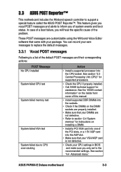
...of the problem. These POST messages are not defective. • Refer to section "2.4 System memory" for assistance. You can record your package. ASUS P4P800-E Deluxe motherboard 3-3 See section "4.4 Advanced menu." In case of a boot failure, you only set to CPU over-clocking Action • Install a ... Vocal POST messages Following is not defective. • Check your CPU settings in BIOS and make sure you will hear the specific cause of system events and boot status. See the "ASUS contact information" on the inside front cover of this manual. • Install supported...
...of the problem. These POST messages are not defective. • Refer to section "2.4 System memory" for assistance. You can record your package. ASUS P4P800-E Deluxe motherboard 3-3 See section "4.4 Advanced menu." In case of a boot failure, you only set to CPU over-clocking Action • Install a ... Vocal POST messages Following is not defective. • Check your CPU settings in BIOS and make sure you will hear the specific cause of system events and boot status. See the "ASUS contact information" on the inside front cover of this manual. • Install supported...
P4P800-E Deluxe User's manual for English Version E1867
Page 64
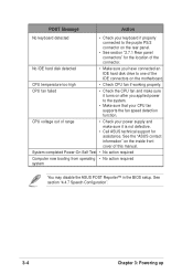
...range • Check your power supply and make sure it is not defective. • Call ASUS technical support for the location of this manual. See section "4.4.7 Speech Configuration". 3-4 Chapter 3: Powering up See the "ASUS contact information" on the motherboard. No IDE hard disk detected • Make sure you applied... Power-On Self Test • No action required Computer now booting from operating • No action required system You may disable the ASUS POST Reporter™ in the BIOS setup. CPU temperature too high • Check CPU fan if working properly.
...range • Check your power supply and make sure it is not defective. • Call ASUS technical support for the location of this manual. See section "4.4.7 Speech Configuration". 3-4 Chapter 3: Powering up See the "ASUS contact information" on the motherboard. No IDE hard disk detected • Make sure you applied... Power-On Self Test • No action required Computer now booting from operating • No action required system You may disable the ASUS POST Reporter™ in the BIOS setup. CPU temperature too high • Check CPU fan if working properly.


