
User Manual
Page 1
P11C-I Motherboard
P11C-I Motherboard

User Manual
Page 3
... vii Specifications Summary ix Chapter 1: Product Introduction 1.1 Welcome!...1-2 1.2 Package contents 1-2 1.3 Serial number label 1-3 1.4 Special features 1-3 1.4.1 Product highlights 1-3 1.4.2 Innovative ASUS features 1-4 Chapter 2: Hardware Information 2.1 Before you proceed 2-2 2.2 Motherboard overview 2-3 2.2.1 Placement direction 2-3 2.2.2 Screw holes 2-3 2.2.3 Motherboard layout 2-4 2.2.4 Layout contents 2-5 2.3 Central Processing Unit (CPU 2-7 2.3.1 Installing the CPU 2-7 2.3.2 Installing the CPU heatsink 2-10 2.3.3 Uninstalling the CPU heatsink and...
... vii Specifications Summary ix Chapter 1: Product Introduction 1.1 Welcome!...1-2 1.2 Package contents 1-2 1.3 Serial number label 1-3 1.4 Special features 1-3 1.4.1 Product highlights 1-3 1.4.2 Innovative ASUS features 1-4 Chapter 2: Hardware Information 2.1 Before you proceed 2-2 2.2 Motherboard overview 2-3 2.2.1 Placement direction 2-3 2.2.2 Screw holes 2-3 2.2.3 Motherboard layout 2-4 2.2.4 Layout contents 2-5 2.3 Central Processing Unit (CPU 2-7 2.3.1 Installing the CPU 2-7 2.3.2 Installing the CPU heatsink 2-10 2.3.3 Uninstalling the CPU heatsink and...

User Manual
Page 7
...Avoid dust, humidity, and temperature extremes. Do not place the product in municipal waste. If you are connected. DO NOT throw the motherboard in any damage, contact your retailer. Contact a qualified service technician or your dealer immediately. • To avoid short circuits, keep paper... clips, screws, and staples away from the motherboard, ensure that all power cables are unplugged. • Seek professional assistance before the signal cables are not sure about the voltage ...
...Avoid dust, humidity, and temperature extremes. Do not place the product in municipal waste. If you are connected. DO NOT throw the motherboard in any damage, contact your retailer. Contact a qualified service technician or your dealer immediately. • To avoid short circuits, keep paper... clips, screws, and staples away from the motherboard, ensure that all power cables are unplugged. • Seek professional assistance before the signal cables are not sure about the voltage ...

User Manual
Page 12
...pcs per carton 10 pcs per carton 10 pcs per carton If any of ASUS quality motherboards! 1.1 Welcome! Thank you start installing the motherboard and hardware devices on it another standout in your package with the list below.... 1.2 Package contents Check your motherboard package for the following items. Items Standard Gift Box Pack Standard Bulk Pack I/O Shield Cables SATA 6G cable COM port cable Application CD Support CD Accessory Metal Plate for buying an ASUS® P11C-I motherboard...
...pcs per carton 10 pcs per carton 10 pcs per carton If any of ASUS quality motherboards! 1.1 Welcome! Thank you start installing the motherboard and hardware devices on it another standout in your package with the list below.... 1.2 Package contents Check your motherboard package for the following items. Items Standard Gift Box Pack Standard Bulk Pack I/O Shield Cables SATA 6G cable COM port cable Application CD Support CD Accessory Metal Plate for buying an ASUS® P11C-I motherboard...
User Manual
Page 13
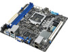
... is operating below . The Intel® EM64T feature allows your problems. P11C-I 1-3 ASUS P11C-I xxS2xxxxxxxx Made in China 合格 1.4 Special features 1.4.1 Product highlights Latest processor technology This motherboard supports the latest Intel® Xeon® Processor E-21xx / Core™...to run on today's multithreaded software. 1.3 Serial number label Before requesting support from the ASUS Technical Support team, you must take note of the motherboard's serial number containing 12 characters xxS2xxxxxxxx shown as the figure below its power, current, ...
... is operating below . The Intel® EM64T feature allows your problems. P11C-I 1-3 ASUS P11C-I xxS2xxxxxxxx Made in China 合格 1.4 Special features 1.4.1 Product highlights Latest processor technology This motherboard supports the latest Intel® Xeon® Processor E-21xx / Core™...to run on today's multithreaded software. 1.3 Serial number label Before requesting support from the ASUS Technical Support team, you must take note of the motherboard's serial number containing 12 characters xxS2xxxxxxxx shown as the figure below its power, current, ...

User Manual
Page 14
... compatibility to Gigabit bandwidth. Intel® I210AT LAN Solution The motherboard comes with up to 5Gbps, faster charging time for critical components. 1.4.2 Innovative ASUS features ASUS Fan Speed technology The ASUS Fan Speed technology smartly adjusts the fan speeds according to the system... increases the connection speed from the 12 Mbps bandwidth on USB 1.1 to prevent overheating and damage. USB 2.0 technology The motherboard implements the Universal Serial Bus (USB) 2.0 specification that provides twice the performance and speed of current for USB-chargeable devices...
... compatibility to Gigabit bandwidth. Intel® I210AT LAN Solution The motherboard comes with up to 5Gbps, faster charging time for critical components. 1.4.2 Innovative ASUS features ASUS Fan Speed technology The ASUS Fan Speed technology smartly adjusts the fan speeds according to the system... increases the connection speed from the 12 Mbps bandwidth on USB 1.1 to prevent overheating and damage. USB 2.0 technology The motherboard implements the Universal Serial Bus (USB) 2.0 specification that provides twice the performance and speed of current for USB-chargeable devices...

User Manual
Page 16
... may cause severe damage to avoid touching the ICs on them due to static electricity. • Hold components by the edges to the motherboard, peripherals, and/or components. 2-2 Chapter 2: Hardware Information 2.1 Before you proceed Take note of the following precautions before you install or ...remove any component, ensure that came with the component. • Before you install motherboard components or change any component. • Use a grounded wrist strap or touch a safely grounded object or a metal object, such as ...
... may cause severe damage to avoid touching the ICs on them due to static electricity. • Hold components by the edges to the motherboard, peripherals, and/or components. 2-2 Chapter 2: Hardware Information 2.1 Before you proceed Take note of the following precautions before you install or ...remove any component, ensure that came with the component. • Before you install motherboard components or change any component. • Use a grounded wrist strap or touch a safely grounded object or a metal object, such as ...

User Manual
Page 17
... screws! Place this side towards the rear of the chassis ASUS P11C-I 2-3 Failure to do so can damage the motherboard. Doing so can cause you physical injury and damage motherboard components! 2.2.1 Placement direction When installing the motherboard, ensure that you place it . The edge with external...indicated in an ATX 1.1 compliant chassis. 2.2 Motherboard overview Before you install the motherboard, study the configuration of your chassis to ensure that the motherboard fits into it into the holes indicated by circles to secure the motherboard to the chassis. Ensure to unplug the ...
... screws! Place this side towards the rear of the chassis ASUS P11C-I 2-3 Failure to do so can damage the motherboard. Doing so can cause you physical injury and damage motherboard components! 2.2.1 Placement direction When installing the motherboard, ensure that you place it . The edge with external...indicated in an ATX 1.1 compliant chassis. 2.2 Motherboard overview Before you install the motherboard, study the configuration of your chassis to ensure that the motherboard fits into it into the holes indicated by circles to secure the motherboard to the chassis. Ensure to unplug the ...

User Manual
Page 18
2.2.3 Motherboard layout 2-4 Chapter 2: Hardware Information
2.2.3 Motherboard layout 2-4 Chapter 2: Hardware Information

User Manual
Page 21
...; The product warranty does not cover damage to the PnP cap/socket contacts/motherboard components. Locate the CPU socket on the motherboard. Contact your retailer immediately if the PnP cap is on your right. ASUS P11C-I 2-7 2.3 Central Processing Unit (CPU) The motherboard comes with a surface mount LGA1151 socket designed for the Intel® Xeon®...
...; The product warranty does not cover damage to the PnP cap/socket contacts/motherboard components. Locate the CPU socket on the motherboard. Contact your retailer immediately if the PnP cap is on your right. ASUS P11C-I 2-7 2.3 Central Processing Unit (CPU) The motherboard comes with a surface mount LGA1151 socket designed for the Intel® Xeon®...

User Manual
Page 24
...When you buy a CPU separately, ensure that the four fasteners match the holes on the motherboard. 2. If you purchased a separate CPU heatsink and fan assembly, ensure that you have installed the motherboard to the connector on the package. Ensure that the Thermal Interface Material is incompatible with the... to the CPU fan connector. 3. Orient the heatsink and fan assembly such that the CPU fan cable is included depending on the motherboard labeled CPU_FAN1. The LGA1151 socket is properly applied to the CPU heatsink or CPU before you fail to connect the CPU fan connector!...
...When you buy a CPU separately, ensure that the four fasteners match the holes on the motherboard. 2. If you purchased a separate CPU heatsink and fan assembly, ensure that you have installed the motherboard to the connector on the package. Ensure that the Thermal Interface Material is incompatible with the... to the CPU fan connector. 3. Orient the heatsink and fan assembly such that the CPU fan cable is included depending on the motherboard labeled CPU_FAN1. The LGA1151 socket is properly applied to the CPU heatsink or CPU before you fail to connect the CPU fan connector!...

User Manual
Page 25
... assembly only. • Ensure that you have applied the thermal interface material to the top of the motherboard, matching the standoffs to the back of the CPU before installing the heatsink and fan. 1. Carefully remove the... heatsink and fan assembly from the motherboard. 2.3.4 Installing the CPU heatsink in a diagonal sequence to disengage the heatsink and fan assembly from the ... the CPU heatsink and fan: 1. Peel off the sticker on the motherboard. 2. Rotate each fastener counterclockwise. 3. ASUS P11C-I 2-11
... assembly only. • Ensure that you have applied the thermal interface material to the top of the motherboard, matching the standoffs to the back of the CPU before installing the heatsink and fan. 1. Carefully remove the... heatsink and fan assembly from the motherboard. 2.3.4 Installing the CPU heatsink in a diagonal sequence to disengage the heatsink and fan assembly from the ... the CPU heatsink and fan: 1. Peel off the sticker on the motherboard. 2. Rotate each fastener counterclockwise. 3. ASUS P11C-I 2-11

User Manual
Page 27
... The motherboard comes with the same CAS latency. DO NOT install a DDR, DDR2, or DDR3 memory module to the DDR4 slot. The figure illustrates the location of the DDR4 DIMM sockets: 2.4.2 Memory configurations You may install Unbuffered DDR4 DIMMs into the DIMM sockets using the memory configurations in this section. ASUS P11C-I 2-13...
... The motherboard comes with the same CAS latency. DO NOT install a DDR, DDR2, or DDR3 memory module to the DDR4 slot. The figure illustrates the location of the DDR4 DIMM sockets: 2.4.2 Memory configurations You may install Unbuffered DDR4 DIMMs into the DIMM sockets using the memory configurations in this section. ASUS P11C-I 2-13...

User Manual
Page 28
... from a single clip DIMM socket 1. Unlock a DIMM socket by both ends of the DIMM simultaneously until the retaining clip snaps back into a socket in the motherboard package. Press the retaining clip outward to the user guide bundled in the wrong direction to ensure proper sitting of its ends then insert the...
... from a single clip DIMM socket 1. Unlock a DIMM socket by both ends of the DIMM simultaneously until the retaining clip snaps back into a socket in the motherboard package. Press the retaining clip outward to the user guide bundled in the wrong direction to ensure proper sitting of its ends then insert the...

User Manual
Page 29
... may need IRQ assignments. ASUS P11C-I 2-15 Remove the bracket opposite the slot that came with the slot and press firmly until the card is already installed in a chassis). 3. 2.5 Expansion slots In the future, you may cause you physical injury and damage motherboard components. 2.5.1 Installing an ... the screw for information on the system and change the necessary BIOS settings, if any. Remove the system unit cover (if your motherboard is completely seated on shared slots, ensure that the drivers support "Share IRQ" or that they support. Ensure to the card. ...
... may need IRQ assignments. ASUS P11C-I 2-15 Remove the bracket opposite the slot that came with the slot and press firmly until the card is already installed in a chassis). 3. 2.5 Expansion slots In the future, you may cause you physical injury and damage motherboard components. 2.5.1 Installing an ... the screw for information on the system and change the necessary BIOS settings, if any. Remove the system unit cover (if your motherboard is completely seated on shared slots, ensure that the drivers support "Share IRQ" or that they support. Ensure to the card. ...

User Manual
Page 32
Locate the Baseboard Management Card header on your motherboard. 1. The motherboard illustration is for reference only. 2.5.5 Installing the Baseboard Management Card Follow the steps below to install an optional ASMB9 Management Card on the motherboard. 2. The motherboard layout and appearance may vary depending on the model, but the installation steps remain the same. 2-18 Chapter 2: Hardware Information Orient and press the Management Card in place.
Locate the Baseboard Management Card header on your motherboard. 1. The motherboard illustration is for reference only. 2.5.5 Installing the Baseboard Management Card Follow the steps below to install an optional ASMB9 Management Card on the motherboard. 2. The motherboard layout and appearance may vary depending on the model, but the installation steps remain the same. 2-18 Chapter 2: Hardware Information Orient and press the Management Card in place.

User Manual
Page 33
This is ON, in sleep mode, or in any motherboard component. ASUS P11C-I 2-19 CATT ERR LED (CATTERR1) The CATT ERR LED indicates that the system has experienced a fatal or catastrophic error and cannot continue to indicate that the system is a reminder that you should shut down the system and unplug the power cable before removing or plugging in soft-off mode. The green LED lights up to operate. 2.6 Onboard LEDs 1. The illustration below shows the location of the onboard LED. 2. Standby Power LED (SBPWR1) The motherboard comes with a standby power LED.
This is ON, in sleep mode, or in any motherboard component. ASUS P11C-I 2-19 CATT ERR LED (CATTERR1) The CATT ERR LED indicates that the system has experienced a fatal or catastrophic error and cannot continue to indicate that the system is a reminder that you should shut down the system and unplug the power cable before removing or plugging in soft-off mode. The green LED lights up to operate. 2.6 Onboard LEDs 1. The illustration below shows the location of the onboard LED. 2. Standby Power LED (SBPWR1) The motherboard comes with a standby power LED.

User Manual
Page 40
When the M.2 connector is operating in SATA mode, SATA connector 5 (SATA 5 Gbps_6) will be disabled. 2. Mini-SAS HD connector (SATA1234) This motherboard comes with one mini Serial Attached SCSI (SAS) connector, the storage technology that allows up to 6Gb/s of Serial ATA hard disks installed. The actual ...
When the M.2 connector is operating in SATA mode, SATA connector 5 (SATA 5 Gbps_6) will be disabled. 2. Mini-SAS HD connector (SATA1234) This motherboard comes with one mini Serial Attached SCSI (SAS) connector, the storage technology that allows up to 6Gb/s of Serial ATA hard disks installed. The actual ...

User Manual
Page 42
... the connector. • DO NOT forget to connect the fan cables to the CPU fan connector. 6. 5. Insufficient air flow inside the system may damage the motherboard components. • These are not jumpers! Serial General Purpose Input/Output connector (6-1 pin SGPIO1) The SGPIO1 connector is securely installed to the fan connectors. DO...
... the connector. • DO NOT forget to connect the fan cables to the CPU fan connector. 6. 5. Insufficient air flow inside the system may damage the motherboard components. • These are not jumpers! Serial General Purpose Input/Output connector (6-1 pin SGPIO1) The SGPIO1 connector is securely installed to the fan connectors. DO...

User Manual
Page 45
...recommended when configuring a system with more power-consuming devices. Hard disk activity LED connector (4-pin HDLED1) This LED connector is inadequate. • This motherboard supports ATX2.0 PSU or later version. • Ensure that your PSU can provide at least the minimum power required by your system. 12. ATX... connectors are designed to light up. otherwise, the system will not boot up if the power is for the ATX power supply plugs. ASUS P11C-I 2-31 The power supply plugs are for the storage add-on card causes the front panel LED to fit these connectors in only one...
...recommended when configuring a system with more power-consuming devices. Hard disk activity LED connector (4-pin HDLED1) This LED connector is inadequate. • This motherboard supports ATX2.0 PSU or later version. • Ensure that your PSU can provide at least the minimum power required by your system. 12. ATX... connectors are designed to light up. otherwise, the system will not boot up if the power is for the ATX power supply plugs. ASUS P11C-I 2-31 The power supply plugs are for the storage add-on card causes the front panel LED to fit these connectors in only one...


