User Manual
Page 21
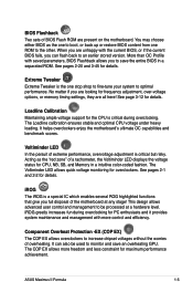
.... The COP EX allows more control and efficiency. See pages 2-1 and 2-2 for details. iROG greatly increases fun during overclocking. ASUS Maximus II Formula 1-5 See page 3-12 for details. Voltiminder LED In the persuit of extreme performance, overvoltage adjustment is critical during overclocking for PC...under heavy loading. The Voltiminder LED allows quick voltage monitoring for frequency adjustment, over-voltage options, or memory timing settings, they are present on the motherboard. No matter if you can also be processed at any stage! It can flash back to an ...
.... The COP EX allows more control and efficiency. See pages 2-1 and 2-2 for details. iROG greatly increases fun during overclocking. ASUS Maximus II Formula 1-5 See page 3-12 for details. Voltiminder LED In the persuit of extreme performance, overvoltage adjustment is critical during overclocking for PC...under heavy loading. The Voltiminder LED allows quick voltage monitoring for frequency adjustment, over-voltage options, or memory timing settings, they are present on the motherboard. No matter if you can also be processed at any stage! It can flash back to an ...
User Manual
Page 27
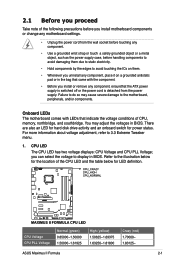
...status. There are also an LED for hard disk drive activity and an onboard switch for LED definition. ASUS Maximus II Formula 2-1 You may cause severe damage to the motherboard, peripherals, and/or components. CPU Voltage CPU PLL Voltage Normal (green) 0.85000-1.50000 1.50000-1.61925 ... for the location of CPU, memory, northbridge, and southbridge. 2.1 Before you proceed Take note of the following precautions before you install motherboard components or change any component, place it on them. • Whenever you uninstall any motherboard settings. • Unplug the power ...
...status. There are also an LED for hard disk drive activity and an onboard switch for LED definition. ASUS Maximus II Formula 2-1 You may cause severe damage to the motherboard, peripherals, and/or components. CPU Voltage CPU PLL Voltage Normal (green) 0.85000-1.50000 1.50000-1.61925 ... for the location of CPU, memory, northbridge, and southbridge. 2.1 Before you proceed Take note of the following precautions before you install motherboard components or change any component, place it on them. • Whenever you uninstall any motherboard settings. • Unplug the power ...
User Manual
Page 40
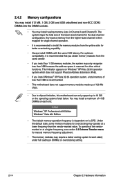
... Windows® XP/Vista 32-bit operation system, a total memory of less than 3GB is recommended. • This motherboard does not support memory modules made up of 128 Mb chips. • Due to chipset limitation, this motherboard can only support up to 16 GB on its SPD. Under...• It is recommended to work stably under full loading (4 DIMMs) or overclocking setting. 2-14 Chapter 2: Hardware information Any excess memory from the yellow slots for other critical functions. You may install varying memory sizes in Channel A and Channel B. To operate at the vendormarked or at a ...
... Windows® XP/Vista 32-bit operation system, a total memory of less than 3GB is recommended. • This motherboard does not support memory modules made up of 128 Mb chips. • Due to chipset limitation, this motherboard can only support up to 16 GB on its SPD. Under...• It is recommended to work stably under full loading (4 DIMMs) or overclocking setting. 2-14 Chapter 2: Hardware information Any excess memory from the yellow slots for other critical functions. You may install varying memory sizes in Channel A and Channel B. To operate at the vendormarked or at a ...
User Manual
Page 45
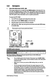
.... You can automatically reset CPU parameter settings to re-enter data. Hold down and reboot the system so the BIOS can clear the CMOS memory of memory timing or chipset voltage and the power button fails to clear the system setup information such as system passwords. 2.6 Jumpers 1. ASUS Maximus II Formula 2-19 Turn OFF the computer and... moved to the Disable position, but the shutdwon function in S0 mode (DOS mode) still works. • Make sure to re-enter your previous BIOS settings after you easily to function, pressing down the system and clear CMOS simultaneously.
.... You can automatically reset CPU parameter settings to re-enter data. Hold down and reboot the system so the BIOS can clear the CMOS memory of memory timing or chipset voltage and the power button fails to clear the system setup information such as system passwords. 2.6 Jumpers 1. ASUS Maximus II Formula 2-19 Turn OFF the computer and... moved to the Disable position, but the shutdwon function in S0 mode (DOS mode) still works. • Make sure to re-enter your previous BIOS settings after you easily to function, pressing down the system and clear CMOS simultaneously.
User Manual
Page 65
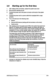
... Connect the power cord to disabled No keyboard detected One continuous beep followed by two short beeps then a pause (repeated) No memory detected One continuous beep followed by three No VGA detected short beeps One continuous beep followed by four short beeps Hardware component failure 7....connections, replace the system case cover. 2. BIOS Beep Description One short beep VGA detected Quick boot set to the power connector at the back of the system chassis. 4. ASUS Maximus II Formula 2-39 Be sure that is equipped with ATX power supplies, the system LED lights up for assistance...
... Connect the power cord to disabled No keyboard detected One continuous beep followed by two short beeps then a pause (repeated) No memory detected One continuous beep followed by three No VGA detected short beeps One continuous beep followed by four short beeps Hardware component failure 7....connections, replace the system case cover. 2. BIOS Beep Description One short beep VGA detected Quick boot set to the power connector at the back of the system chassis. 4. ASUS Maximus II Formula 2-39 Be sure that is equipped with ATX power supplies, the system LED lights up for assistance...

User Manual
Page 84
...the northbridge voltage. When you to 2.00V with a 0.02V interval. North Bridge Voltage [Auto] Allows you set the NB LED Selection item to page 2-2 for memory LED definition. The text color in the configuration field indicates voltage condition. Refer to page 2-2 for northbridge LED... definition. Setting a high FSB termination voltage may make the system unstable. Refer to [NB], the onboard ...
...the northbridge voltage. When you to 2.00V with a 0.02V interval. North Bridge Voltage [Auto] Allows you set the NB LED Selection item to page 2-2 for memory LED definition. The text color in the configuration field indicates voltage condition. Refer to page 2-2 for northbridge LED... definition. Setting a high FSB termination voltage may make the system unstable. Refer to [NB], the onboard ...

User Manual
Page 85
...interval. CPU GTL Reference (0/1/2/3) [Auto] Allows you to set the NB GTL reference voltage. Set to [Disabled] to follow Intel specifications, or to [Enabled] to page 2-2 for the safe mode. Configuration options: [Auto] [Disabled] [Enabled] ASUS Maximus II Formula 3-17 South Bridge 1.5 Voltage [Auto] Allows you to... [+12.5mV] [+25.0mV] [+37.5mV]-[+187.5mV] North Bridge DDR Reference [Auto] Allows you to set the northbridge memory reference voltage, or you set the SB LED Selection item to [SB 1.1], the onboard southbridge LED displays southbridge voltage condition. When you to page...
...interval. CPU GTL Reference (0/1/2/3) [Auto] Allows you to set the NB GTL reference voltage. Set to [Disabled] to follow Intel specifications, or to [Enabled] to page 2-2 for the safe mode. Configuration options: [Auto] [Disabled] [Enabled] ASUS Maximus II Formula 3-17 South Bridge 1.5 Voltage [Auto] Allows you to... [+12.5mV] [+25.0mV] [+37.5mV]-[+187.5mV] North Bridge DDR Reference [Auto] Allows you to set the northbridge memory reference voltage, or you set the SB LED Selection item to [SB 1.1], the onboard southbridge LED displays southbridge voltage condition. When you to page...

User Manual
Page 94
...] Initiate Graphic Adapter [PEG/PCI] Allows you install 64bit operating system. Select an item then press to malfunction. Configuration options: [Disabled] [Enabled] Memory Hole [Disabled] Allows you to change the advanced chipset settings. Configuration options: [PCI/PEG] [PEG/PCI] 3-26 Chapter 4: BIOS setup DISABLE: Do not allow remapping of the overlapped PCI...
...] Initiate Graphic Adapter [PEG/PCI] Allows you install 64bit operating system. Select an item then press to malfunction. Configuration options: [Disabled] [Enabled] Memory Hole [Disabled] Allows you to change the advanced chipset settings. Configuration options: [PCI/PEG] [PEG/PCI] 3-26 Chapter 4: BIOS setup DISABLE: Do not allow remapping of the overlapped PCI...

User Manual
Page 147
ASUS Maximus II Formula 4-31 The options on the AI Suite main window. 4.3.9 ASUS AI Booster The ASUS AI Booster application allows you to overclock the CPU speed in WIndows® environment without the hassle of booting the BIOS. After installing AI Suite from the bundled support DVD, you can launch the utility by double-clicking the AI Suite icon on the Windows® OS taskbar and click the AI Booster button on the taskbar allow you to use the default settings, adjust CPU/ Memory/PCI-E frequency manually, or create and apply your personal overclocking configurations.
ASUS Maximus II Formula 4-31 The options on the AI Suite main window. 4.3.9 ASUS AI Booster The ASUS AI Booster application allows you to overclock the CPU speed in WIndows® environment without the hassle of booting the BIOS. After installing AI Suite from the bundled support DVD, you can launch the utility by double-clicking the AI Suite icon on the Windows® OS taskbar and click the AI Booster button on the taskbar allow you to use the default settings, adjust CPU/ Memory/PCI-E frequency manually, or create and apply your personal overclocking configurations.
User Manual
Page 172
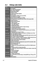
...fails, keep beeping the speaker. Auto detect flash type to load appropriate flash R/W codes into chipset. Auto detect ports for 0-640K memory address. 2. Program chipset default values into the run time area in CMOS circuitry. Initialize multi-language 2. A-4 Appendix: CPU features ...internal MTRR (Pentium class CPU) for keyboard & mouse followed by a port & interface swap (optional). 3. Measure CPU speed. 5. Also set real-time clock power status, and then check for override. Example: onboard IDE controller. 4. Invoke video BIOS. Reset keyboard. Blank out screen...
...fails, keep beeping the speaker. Auto detect flash type to load appropriate flash R/W codes into chipset. Auto detect ports for 0-640K memory address. 2. Program chipset default values into the run time area in CMOS circuitry. Initialize multi-language 2. A-4 Appendix: CPU features ...internal MTRR (Pentium class CPU) for keyboard & mouse followed by a port & interface swap (optional). 3. Measure CPU speed. 5. Also set real-time clock power status, and then check for override. Example: onboard IDE controller. 4. Invoke video BIOS. Reset keyboard. Blank out screen...

User Manual
Page 173
... devices. Call chipset power management hook. 2. ASUS Maximus II Formula A-5 Initialize floppy controller 2. Detect serial ports & parallel ports. Recover the text fond used by testing the last double word of M1 CPU 2. If password is set, ask for channel 2. Test 8259 interrupt mask bits for password. Calculate total memory by EPA logo (not for channel 1. Initialize...
... devices. Call chipset power management hook. 2. ASUS Maximus II Formula A-5 Initialize floppy controller 2. Detect serial ports & parallel ports. Recover the text fond used by testing the last double word of M1 CPU 2. If password is set, ask for channel 2. Test 8259 interrupt mask bits for password. Calculate total memory by EPA logo (not for channel 1. Initialize...

User Manual
Page 174
... 6. Initialize APM 8. Build MSIRQ routing table. Switch screen back to PCI devices 7. Assign IRQs to text mode 4. Set CMOS century to 20h or 19h 4. Load CMOS time into DOS timer tick 5. Clear noise of memory. 5. NET PC: Build SYSID structure 3. Build MP table 2. Boot attempt (INT 19h) A-6 Appendix: CPU features Update keyboard...
... 6. Initialize APM 8. Build MSIRQ routing table. Switch screen back to PCI devices 7. Assign IRQs to text mode 4. Set CMOS century to 20h or 19h 4. Load CMOS time into DOS timer tick 5. Clear noise of memory. 5. NET PC: Build SYSID structure 3. Build MP table 2. Boot attempt (INT 19h) A-6 Appendix: CPU features Update keyboard...


