
User Guide
Page 1
Motherboard MAXIMUS VII FORMULA Series
Motherboard MAXIMUS VII FORMULA Series
User Guide
Page 3
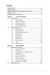
Contents Safety information...vii About this guide...viii MAXIMUS VII FORMULA Series specifications summary x Package contents...xv Installation tools and components xvi Chapter 1: Product Introduction 1.1 Special features 1-1 1.1.1 Product highlights 1-1 1.1.2 ROG Gaming Features 1-2 1.1.3 ROG Exclusive Features 1-3 1.1.4 ASUS Special Features 1-3 1.1.5 ROG rich bundled software 1-4 1.2 Motherboard overview 1-5 1.2.1 Before you proceed 1-5 1.2.2 Motherboard layout 1-6 1.2.3 Central Processing Unit (CPU 1-8 1.2.4 System memory 1-9 1.2.5 Expansion slots 1-24...
Contents Safety information...vii About this guide...viii MAXIMUS VII FORMULA Series specifications summary x Package contents...xv Installation tools and components xvi Chapter 1: Product Introduction 1.1 Special features 1-1 1.1.1 Product highlights 1-1 1.1.2 ROG Gaming Features 1-2 1.1.3 ROG Exclusive Features 1-3 1.1.4 ASUS Special Features 1-3 1.1.5 ROG rich bundled software 1-4 1.2 Motherboard overview 1-5 1.2.1 Before you proceed 1-5 1.2.2 Motherboard layout 1-6 1.2.3 Central Processing Unit (CPU 1-8 1.2.4 System memory 1-9 1.2.5 Expansion slots 1-24...
User Guide
Page 4
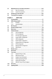
2.3 Motherboard rear and audio connections 2-16 2.3.1 Rear I/O connection 2-16 2.3.2 Audio I/O connections 2-17 2.4 Starting up for the first time 2-21 2.5 Turning off the computer 2-21 Chapter 3:...Network Stack Configuration 3-43 3.6.10 ROG Effects 3-43 3.7 Monitor menu 3-44 3.8 Boot menu 3-47 3.9 Tool menu 3-53 3.9.1 ASUS EZ Flash 2 Utility 3-53 3.9.2 ROG Secure Erase 3-53 3.9.3 Graphics Card Information 3-54 3.9.4 ASUS Overclocking Profile 3-55 3.9.5 ASUS SPD Information 3-56 3.9.6 ROG OC Panel H-Key Configure 3-57 3.10 Exit menu 3-58 3.11 Updating BIOS 3-59 iv
2.3 Motherboard rear and audio connections 2-16 2.3.1 Rear I/O connection 2-16 2.3.2 Audio I/O connections 2-17 2.4 Starting up for the first time 2-21 2.5 Turning off the computer 2-21 Chapter 3:...Network Stack Configuration 3-43 3.6.10 ROG Effects 3-43 3.7 Monitor menu 3-44 3.8 Boot menu 3-47 3.9 Tool menu 3-53 3.9.1 ASUS EZ Flash 2 Utility 3-53 3.9.2 ROG Secure Erase 3-53 3.9.3 Graphics Card Information 3-54 3.9.4 ASUS Overclocking Profile 3-55 3.9.5 ASUS SPD Information 3-56 3.9.6 ROG OC Panel H-Key Configure 3-57 3.10 Exit menu 3-58 3.11 Updating BIOS 3-59 iv
User Guide
Page 7
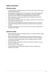
Operation safety • Before installing the motherboard and adding devices on it may become wet. • Place the product on a stable surface. • If you are using, contact your local power company. &#... circuit. • Ensure that the power cables for the devices are unplugged before the signal cables are not damaged. vii If you add a device. • Before connecting or removing signal cables from the motherboard, ensure that came with the product, contact a qualified service technician or your retailer. Safety information Electrical safety •...
Operation safety • Before installing the motherboard and adding devices on it may become wet. • Place the product on a stable surface. • If you are using, contact your local power company. &#... circuit. • Ensure that the power cables for the devices are unplugged before the signal cables are not damaged. vii If you add a device. • Before connecting or removing signal cables from the motherboard, ensure that came with the product, contact a qualified service technician or your retailer. Safety information Electrical safety •...

User Guide
Page 8
...2. How this guide This user guide contains the information you have been added by your dealer. ASUS website The ASUS website (www.asus.com) provides updated information on the motherboard. • Chapter 2: Basic Installation This chapter lists the hardware setup procedures that may have to ... documentation Your product package may include optional documentation, such as warranty flyers, that you need when installing and configuring the motherboard. About this guide is organized This guide contains the following sources for additional information and for product and software updates. ...
...2. How this guide This user guide contains the information you have been added by your dealer. ASUS website The ASUS website (www.asus.com) provides updated information on the motherboard. • Chapter 2: Basic Installation This chapter lists the hardware setup procedures that may have to ... documentation Your product package may include optional documentation, such as warranty flyers, that you need when installing and configuring the motherboard. About this guide is organized This guide contains the following sources for additional information and for product and software updates. ...
User Guide
Page 15
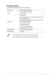
... ROG MAXIMUS VII FORMULA 4 x 2-in-1 SATA 6Gb/s cables 1 x SLI™ cable 1 x I/O Shield 1 x mPCIe Combo III card with dual band Wi-Fi 802.11a/b/ g/n/ac + Bluetooth v4.0 1 x ASUS 2T2R dual band Wi-Fi moving antennas (Wi-Fi 802.11a/b/g/n/ac compliant) 1 x 2-in-1 Q-Connector Kit 1 x ROG Door Hanger 1 x 12-in-1 ROG Cable Label 1 x Watch Dogs game coupon* ROG motherboard...
... ROG MAXIMUS VII FORMULA 4 x 2-in-1 SATA 6Gb/s cables 1 x SLI™ cable 1 x I/O Shield 1 x mPCIe Combo III card with dual band Wi-Fi 802.11a/b/ g/n/ac + Bluetooth v4.0 1 x ASUS 2T2R dual band Wi-Fi moving antennas (Wi-Fi 802.11a/b/g/n/ac compliant) 1 x 2-in-1 Q-Connector Kit 1 x ROG Door Hanger 1 x 12-in-1 ROG Cable Label 1 x Watch Dogs game coupon* ROG motherboard...
User Guide
Page 16
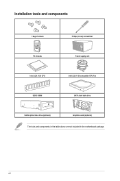
xvi Installation tools and components 1 bag of screws Philips (cross) screwdriver PC chassis Power supply unit Intel LGA 1150 CPU Intel LGA 1150 compatible CPU Fan DDR3 DIMM SATA hard disk drive SATA optical disc drive (optional) Graphics card (optional) The tools and components in the table above are not included in the motherboard package.
xvi Installation tools and components 1 bag of screws Philips (cross) screwdriver PC chassis Power supply unit Intel LGA 1150 CPU Intel LGA 1150 compatible CPU Fan DDR3 DIMM SATA hard disk drive SATA optical disc drive (optional) Graphics card (optional) The tools and components in the table above are not included in the motherboard package.
User Guide
Page 17
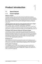
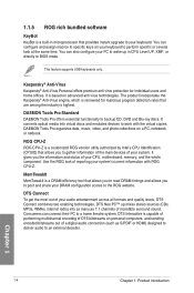
... Chapter 1 ASUS MAXIMUS VII FORMULA 1-1 It utilizes the serial point-to support multi-GPU SLI®/ CrossFireX™ graphics cards for 4th, New 4th, and 5th generation Intel® Core™ i7/Intel® Core™ i5/Intel® Core™ i3, Pentium® and Celeron® processors This motherboard supports 4th,..., the fastest performance, the most innovative ideas, and we excel in the LGA1150 package. SLI®/CrossFire™ On-Demand This motherboard features a unique PCIe 3.0 bridge chip to -point links, which increases bandwidth and enhances the system's performance.
... Chapter 1 ASUS MAXIMUS VII FORMULA 1-1 It utilizes the serial point-to support multi-GPU SLI®/ CrossFireX™ graphics cards for 4th, New 4th, and 5th generation Intel® Core™ i7/Intel® Core™ i5/Intel® Core™ i3, Pentium® and Celeron® processors This motherboard supports 4th,..., the fastest performance, the most innovative ideas, and we excel in the LGA1150 package. SLI®/CrossFire™ On-Demand This motherboard features a unique PCIe 3.0 bridge chip to -point links, which increases bandwidth and enhances the system's performance.
User Guide
Page 19
... can also release the unused memory of system memory and turns it the perfect motherboard for compatible USB 3.0 peripherals without entering the existing BIOS or operating system. Chapter 1 ASUS MAXIMUS VII FORMULA 1-3 The BlackWing Chokes handles pressures with better low temperature tolerance. Plus, this ...get auto data backup and restore. It allows you want to overclock to, and the motherboard will do the rest. 1.1.4 ASUS Special Features AI Suite 3 With its user-friendly interface, ASUS AI Suite 3 consolidates all -in it to 90% efficiency under normal operation. Install...
... can also release the unused memory of system memory and turns it the perfect motherboard for compatible USB 3.0 peripherals without entering the existing BIOS or operating system. Chapter 1 ASUS MAXIMUS VII FORMULA 1-3 The BlackWing Chokes handles pressures with better low temperature tolerance. Plus, this ...get auto data backup and restore. It allows you want to overclock to, and the motherboard will do the rest. 1.1.4 ASUS Special Features AI Suite 3 With its user-friendly interface, ASUS AI Suite 3 consolidates all -in it to 90% efficiency under normal operation. Install...
User Guide
Page 20
... emulates devices to an external decoder. You can connect their PC to backup CD, DVD and Blu-ray discs. You can also configure your CPU, motherboard, memory, and the whole component.
... emulates devices to an external decoder. You can connect their PC to backup CD, DVD and Blu-ray discs. You can also configure your CPU, motherboard, memory, and the whole component.
User Guide
Page 21
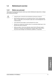
Chapter 1 ASUS MAXIMUS VII FORMULA 1-5 Failure to do so may cause severe damage to avoid touching the ICs on them. • Whenever you uninstall any component, place it on a grounded antistatic pad or in the bag that came with the component. • Before you install motherboard components or... supply case, to avoid damaging them due to static electricity. • Hold components by the edges to the motherboard, peripherals, or components. 1.2 Motherboard overview 1.2.1 Before you proceed Take note of the following precautions before you install or remove any component, ensure that...
Chapter 1 ASUS MAXIMUS VII FORMULA 1-5 Failure to do so may cause severe damage to avoid touching the ICs on them. • Whenever you uninstall any component, place it on a grounded antistatic pad or in the bag that came with the component. • Before you install motherboard components or... supply case, to avoid damaging them due to static electricity. • Hold components by the edges to the motherboard, peripherals, or components. 1.2 Motherboard overview 1.2.1 Before you proceed Take note of the following precautions before you install or remove any component, ensure that...
User Guide
Page 22
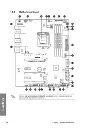
1.2.2 Motherboard layout Chapter 1 Refer to Internal connectors and Rear I/O connection for more information about rear panel connectors and internal connectors. 1-6 Chapter 1: Product introduction
1.2.2 Motherboard layout Chapter 1 Refer to Internal connectors and Rear I/O connection for more information about rear panel connectors and internal connectors. 1-6 Chapter 1: Product introduction
User Guide
Page 24
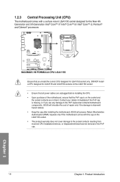
... only if the motherboard comes with a surface mount LGA1150 socket designed for the New 4th Generation and 5th Generation Intel® Core™ i7/ Intel® Core™ i5/ Intel® Core™ i3, Pentium®, and Celeron® processors Ensure that all power cables are not bent. ASUS will shoulder the...
... only if the motherboard comes with a surface mount LGA1150 socket designed for the New 4th Generation and 5th Generation Intel® Core™ i7/ Intel® Core™ i5/ Intel® Core™ i3, Pentium®, and Celeron® processors Ensure that all power cables are not bent. ASUS will shoulder the...
User Guide
Page 25
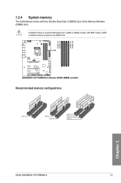
Recommended memory configurations Chapter 1 ASUS MAXIMUS VII FORMULA 1-9 DO NOT install a DDR or DDR2 memory module to the DDR3 slot. A DDR3 module is notched differently from a DDR or DDR2 module. 1.2.4 System memory The motherboard comes with four Double Data Rate 3 (DDR3) Dual Inline Memory Modules (DIMM) slots.
Recommended memory configurations Chapter 1 ASUS MAXIMUS VII FORMULA 1-9 DO NOT install a DDR or DDR2 memory module to the DDR3 slot. A DDR3 module is notched differently from a DDR or DDR2 module. 1.2.4 System memory The motherboard comes with four Double Data Rate 3 (DDR3) Dual Inline Memory Modules (DIMM) slots.
User Guide
Page 26
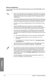
...want to the memory address limitation on 32-bit Windows OS, when you install 4GB or more on the motherboard, the actual usable memory for manual memory frequency adjustment. • For system stability, use of these ... the correct memory modules. • Due to install 4GB or more memory on the motherboard. For optimal compatibility, we recommend that you are using a 32-bit Windows OS. com/kb/929605/en-us.... • This motherboard does not support DIMMs made up of the same version or date code (D/C) from the same vendor...
...want to the memory address limitation on 32-bit Windows OS, when you install 4GB or more on the motherboard, the actual usable memory for manual memory frequency adjustment. • For system stability, use of these ... the correct memory modules. • Due to install 4GB or more memory on the motherboard. For optimal compatibility, we recommend that you are using a 32-bit Windows OS. com/kb/929605/en-us.... • This motherboard does not support DIMMs made up of the same version or date code (D/C) from the same vendor...

User Guide
Page 27
...-14-36 1.65 DIMM socket support (Optional) 2 4 • • • • • • • Chapter 1 ASUS MAXIMUS VII FORMULA 1-11 Size SS/ Chip Chip DS Brand NO. Size SS/ DS Chip Chip Brand NO. Size SS/ DS Chip Chip Brand NO. Timing ...36 1.65 DIMM socket support (Optional) 2 4 • • • • DDR3 3000 MHz capability Vendors Part No. MAXIMUS VII FORMULA Motherboard Qualified Vendors Lists (QVL) DDR3 3300 MHz capability Vendors Part No. AVEXIR A-DATA "AVD3UH31001204G4CI(XMP)" "AX3U3100W4G12DMV(XMP)" Size SS/ Chip...
...-14-36 1.65 DIMM socket support (Optional) 2 4 • • • • • • • Chapter 1 ASUS MAXIMUS VII FORMULA 1-11 Size SS/ Chip Chip DS Brand NO. Size SS/ DS Chip Chip Brand NO. Size SS/ DS Chip Chip Brand NO. Timing ...36 1.65 DIMM socket support (Optional) 2 4 • • • • DDR3 3000 MHz capability Vendors Part No. MAXIMUS VII FORMULA Motherboard Qualified Vendors Lists (QVL) DDR3 3300 MHz capability Vendors Part No. AVEXIR A-DATA "AVD3UH31001204G4CI(XMP)" "AX3U3100W4G12DMV(XMP)" Size SS/ Chip...

User Guide
Page 40
Chapter 1 Slot No. Failure to do so may cause you physical injury and damage motherboard components. Slot Description 1 PCIe 2.0 x1_1 slot 2 PCIe 3.0/2.0 x16/x8_1 slot 3 PCIe 2.0 x1_2 slot 4 PCIe 3.0/2.0 x8_2 slot 5 PCIe 2.0 x1_3 slot 6 PCIe 2.0 x4_3 slot 1-24 Chapter 1: Product introduction 1.2.5 Expansion slots Unplug the power cord before adding or removing expansion cards.
Chapter 1 Slot No. Failure to do so may cause you physical injury and damage motherboard components. Slot Description 1 PCIe 2.0 x1_1 slot 2 PCIe 3.0/2.0 x16/x8_1 slot 3 PCIe 2.0 x1_2 slot 4 PCIe 3.0/2.0 x8_2 slot 5 PCIe 2.0 x1_3 slot 6 PCIe 2.0 x4_3 slot 1-24 Chapter 1: Product introduction 1.2.5 Expansion slots Unplug the power cord before adding or removing expansion cards.
User Guide
Page 41
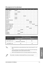
...; mode. • Connect a chassis fan to x8 mode when PCIe_x8_2 slots are occupied. Chapter 1 ASUS MAXIMUS VII FORMULA 1-25 shared - - - - - - - shared - - - - shared - - - - - - - PCIe_x16/x8_1 slot switches to the motherboard connector labeled CHA_FAN1-3A/B when using multiple graphics cards for this motherboard PCIE_x16/x8_1 PCIE_x8_2 PCIE_x4_3 PCIE_x1_1 PCIE_x1_2 PCIE_x1_3 I.G.F.X Intel LAN Controller SATA #0 SATA #1 High Definition Audio...
...; mode. • Connect a chassis fan to x8 mode when PCIe_x8_2 slots are occupied. Chapter 1 ASUS MAXIMUS VII FORMULA 1-25 shared - - - - - - - shared - - - - shared - - - - - - - PCIe_x16/x8_1 slot switches to the motherboard connector labeled CHA_FAN1-3A/B when using multiple graphics cards for this motherboard PCIE_x16/x8_1 PCIE_x8_2 PCIE_x4_3 PCIE_x1_1 PCIE_x1_2 PCIE_x1_3 I.G.F.X Intel LAN Controller SATA #0 SATA #1 High Definition Audio...
User Guide
Page 42
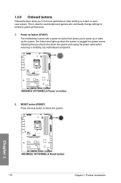
... the system. 1.2.6 Onboard buttons Onboard buttons allow you should shut down the system and unplug the power cable before removing or installing any motherboard component. 2. This is plugged to a power source indicating that allows you to power up or wake up when the system is ideal ...for overclockers and gamers who continually change settings to reboot the system. Power-on button (START) The motherboard comes with a power-on button that you to fine-tune performance when working on a bare or opencase system. Chapter 1 1-26 Chapter 1:...
... the system. 1.2.6 Onboard buttons Onboard buttons allow you should shut down the system and unplug the power cable before removing or installing any motherboard component. 2. This is plugged to a power source indicating that allows you to power up or wake up when the system is ideal ...for overclockers and gamers who continually change settings to reboot the system. Power-on button (START) The motherboard comes with a power-on button that you to fine-tune performance when working on a bare or opencase system. Chapter 1 1-26 Chapter 1:...

User Guide
Page 43
...A message will appear during the tuning process, the system continues memory tuning after the whole tuning process, the DRAM_LED lights continuously. ASUS MAXIMUS VII FORMULA 1-27 Chapter 1 button until the MEMOK_LED memory compatibility tuning for successful boot. • Refer to section Onboard LEDs for the system.... • The DRAM_LED also lights up due to its default settings. • We recommend that are not compatible with the motherboard may cause system boot failure, and the DRAM_LED near the MemOK! button lights continuously. 3. Press the MemOK! To stop memory tuning...
...A message will appear during the tuning process, the system continues memory tuning after the whole tuning process, the DRAM_LED lights continuously. ASUS MAXIMUS VII FORMULA 1-27 Chapter 1 button until the MEMOK_LED memory compatibility tuning for successful boot. • Refer to section Onboard LEDs for the system.... • The DRAM_LED also lights up due to its default settings. • We recommend that are not compatible with the motherboard may cause system boot failure, and the DRAM_LED near the MemOK! button lights continuously. 3. Press the MemOK! To stop memory tuning...


