User Manual
Page 23
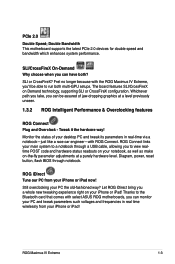
Fret no longer because with select ASUS ROG motherboards, you can have both multi-GPU setups. Whichever path you take, you can monitor your PC and tweak parameters such voltages and frequencies ... Plug and Overclock - SLI or CrossFireX? Tweak it the hardcore way! Double Bandwidth This motherboard supports the latest PCIe 2.0 devices for double speed and bandwidth which enhances system performance. PCIe 2.0 Double Speed; ROG Maximus IV Extreme 1-3 The board features SLI/CrossFireX on your desktop PC and tweak its parameters in real time wirelessly from your...
Fret no longer because with select ASUS ROG motherboards, you can have both multi-GPU setups. Whichever path you take, you can monitor your PC and tweak parameters such voltages and frequencies ... Plug and Overclock - SLI or CrossFireX? Tweak it the hardcore way! Double Bandwidth This motherboard supports the latest PCIe 2.0 devices for double speed and bandwidth which enhances system performance. PCIe 2.0 Double Speed; ROG Maximus IV Extreme 1-3 The board features SLI/CrossFireX on your desktop PC and tweak its parameters in real time wirelessly from your...
User Manual
Page 35
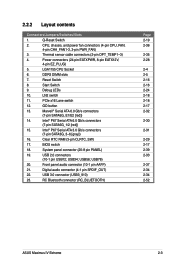
... PANEL) 19. USB56; PCIe x16 Lane switch 12. USB 3.0 connector (USB3_910) 23. Intel® P67 Serial ATA 6.0 Gb/s connectors (7-pin SATA6G_1/2 [red]) 15. RC Bluetooth connector (RC_BLUETOOTH) Page 2-19 2-36 2-35 2-28 2-4 2-5 2-16 2-16 2-24 2-18 2-18 2-17 2-32 2-30 2-31 2-29 2-17 2-39 2-33 2-37 2-34 2-34 2-52 ASUS Maximus IV Extreme 2-3 Q-Reset Switch...
... PANEL) 19. USB56; PCIe x16 Lane switch 12. USB 3.0 connector (USB3_910) 23. Intel® P67 Serial ATA 6.0 Gb/s connectors (7-pin SATA6G_1/2 [red]) 15. RC Bluetooth connector (RC_BLUETOOTH) Page 2-19 2-36 2-35 2-28 2-4 2-5 2-16 2-16 2-24 2-18 2-18 2-17 2-32 2-30 2-31 2-29 2-17 2-39 2-33 2-37 2-34 2-34 2-52 ASUS Maximus IV Extreme 2-3 Q-Reset Switch...

User Manual
Page 46
Slot Description 1 PCIe 2.0 x16/8_1 slot 2 PCIe 2.0 x1_1 slot 3 PCIe 2.0 x16_2 slot 4 PCIe 2.0 x8_3 slot (PCIe 2.0 x16 slot with x8 bandwidth) 5 PCIe 2.0 x16_4 slot 6 PCIe 2.0 x4_1 slot 2-14 Chapter 2: Hardware information NF200 Slot No. 2.2.5 Expansion slots Ensure to do so may cause you physical injury and damage motherboard components. Failure to unplug the power cord before adding or removing expansion cards.
Slot Description 1 PCIe 2.0 x16/8_1 slot 2 PCIe 2.0 x1_1 slot 3 PCIe 2.0 x16_2 slot 4 PCIe 2.0 x8_3 slot (PCIe 2.0 x16 slot with x8 bandwidth) 5 PCIe 2.0 x16_4 slot 6 PCIe 2.0 x4_1 slot 2-14 Chapter 2: Hardware information NF200 Slot No. 2.2.5 Expansion slots Ensure to do so may cause you physical injury and damage motherboard components. Failure to unplug the power cord before adding or removing expansion cards.

User Manual
Page 50
5. When one without removing the cards. 6. LN2 Mode switch With LN2 mode activated, the ROG motherboard is optimized to find out the faulty one of the installed PCIe x16 cards is out of order, you to enable and disable the corresponding PCIe x16 slots. PCIe x16 Lane switch These slide switches allows you can use the slide switch to remedy the cold-boot bug during POST at an extremely low temperature and help the system boot successfully. 2-18 Chapter 2: Hardware information
5. When one without removing the cards. 6. LN2 Mode switch With LN2 mode activated, the ROG motherboard is optimized to find out the faulty one of the installed PCIe x16 cards is out of order, you to enable and disable the corresponding PCIe x16 slots. PCIe x16 Lane switch These slide switches allows you can use the slide switch to remedy the cold-boot bug during POST at an extremely low temperature and help the system boot successfully. 2-18 Chapter 2: Hardware information

User Manual
Page 83
2.3.9 Expension Card installation To install PCIe x16 cards To install PCIe x1 cards To install PCI cards ASUS Maximus IV Extreme 2-51
2.3.9 Expension Card installation To install PCIe x16 cards To install PCIe x1 cards To install PCI cards ASUS Maximus IV Extreme 2-51

User Manual
Page 119
... provides at least 1A on the +5VSB lead. Power On By PCIE [Disabled] [Disabled] Disables the PCIE devices to generate a wake event. [Enabled] Enables the PCIE devices to set the iROG Time Keeper operation mode. Configuration options: [Last State] [Disabled] [Enabled] ASUS Maximus IV Extreme 3-27 This feature requires an ATX power supply that provides at least...
... provides at least 1A on the +5VSB lead. Power On By PCIE [Disabled] [Disabled] Disables the PCIE devices to generate a wake event. [Enabled] Enables the PCIE devices to set the iROG Time Keeper operation mode. Configuration options: [Last State] [Disabled] [Enabled] ASUS Maximus IV Extreme 3-27 This feature requires an ATX power supply that provides at least...

User Manual
Page 166
...; Free Physical Disks ├ PD 0: ST3160812AS └ PD 8: ST3160812AS Information Vendor ID : 1B4B Device ID : 9130 Revision ID : B1 BIOS Version : 1.0.0.1028 Firmware Version: 2.2.0.1105 PCIe Speed Rate : 5.0Gbps Configure SATA as: AHCI Mode ▶ ▶ Help Marvell RAID on the hard disk drives will be used in the array. After...
...; Free Physical Disks ├ PD 0: ST3160812AS └ PD 8: ST3160812AS Information Vendor ID : 1B4B Device ID : 9130 Revision ID : B1 BIOS Version : 1.0.0.1028 Firmware Version: 2.2.0.1105 PCIe Speed Rate : 5.0Gbps Configure SATA as: AHCI Mode ▶ ▶ Help Marvell RAID on the hard disk drives will be used in the array. After...

User Manual
Page 168
... 0: ST3160812AS │ └ PD 8: ST3160812AS └ Free Physical Disks Information Vendor ID : 1B4B Device ID : 9130 Revision ID : B1 BIOS Version : 1.0.0.1028 Firmware Version: 2.2.0.1105 PCIe Speed Rate : 5.0Gbps Configure SATA as: AHCI Mode ▶ ▶ Help Marvell RAID on chip controller.
... 0: ST3160812AS │ └ PD 8: ST3160812AS └ Free Physical Disks Information Vendor ID : 1B4B Device ID : 9130 Revision ID : B1 BIOS Version : 1.0.0.1028 Firmware Version: 2.2.0.1105 PCIe Speed Rate : 5.0Gbps Configure SATA as: AHCI Mode ▶ ▶ Help Marvell RAID on chip controller.

