User Manual
Page 15
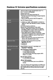
Maximus IV Extreme specifications summary CPU Chipset Memory Expansion Slots Multi-GPU Technology Storage LGA1155 socket for Intel® 2nd Generation Core™ i7 / Core™ i5 / Core&#...;�ir�e�X�™��T�e�c�h�n�o�l�o�g�y Intel® P67 Express Chipset built-in: - 2 x SATA 6Gb/s ports (Red) - 4 x SATA 3Gb/s ports (Gray) - ASUS will update QVL once the DIMMs are available on the next page) xv Some hyper DIMMs only support one...
Maximus IV Extreme specifications summary CPU Chipset Memory Expansion Slots Multi-GPU Technology Storage LGA1155 socket for Intel® 2nd Generation Core™ i7 / Core™ i5 / Core&#...;�ir�e�X�™��T�e�c�h�n�o�l�o�g�y Intel® P67 Express Chipset built-in: - 2 x SATA 6Gb/s ports (Red) - 4 x SATA 3Gb/s ports (Gray) - ASUS will update QVL once the DIMMs are available on the next page) xv Some hyper DIMMs only support one...
User Manual
Page 16
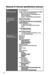
...65533;U��P�a�r�a�m��e�te�r�R��e�c�a�ll�) Maximus IV Extreme specifications summary LAN High Definition Audio Bluetooth Module Accessory Card USB ROG Exclusive Overclocking Features xvi 2 x Intel® ... 2 x USB 3.0 ports at mid-board for front panel support 1 x NEC USB3.0 Controller: - 2 x USB 3.0 ports at rear Intel® P67 Express Chipset: - 9 x USB 2.0 ports (8 ports at mid-board, 1 port at rear is also for ROG connect) ROG Connect RC Bluetooth ROG iDirect ROG...
...65533;U��P�a�r�a�m��e�te�r�R��e�c�a�ll�) Maximus IV Extreme specifications summary LAN High Definition Audio Bluetooth Module Accessory Card USB ROG Exclusive Overclocking Features xvi 2 x Intel® ... 2 x USB 3.0 ports at mid-board for front panel support 1 x NEC USB3.0 Controller: - 2 x USB 3.0 ports at rear Intel® P67 Express Chipset: - 9 x USB 2.0 ports (8 ports at mid-board, 1 port at rear is also for ROG connect) ROG Connect RC Bluetooth ROG iDirect ROG...
User Manual
Page 35
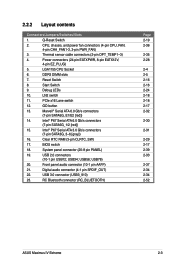
... Front panel audio connector (10-1 pin AAFP) 21. Start Switch 9. USB34; USB78) 20. Reset Switch 8. LN2 switch 11. Intel® P67 Serial ATA 6.0 Gb/s connectors (7-pin SATA6G_1/2 [red]) 15. System panel connector (20-8 pin PANEL) 19. Thermal sensor cable connectors (2-pin ...35 2-28 2-4 2-5 2-16 2-16 2-24 2-18 2-18 2-17 2-32 2-30 2-31 2-29 2-17 2-39 2-33 2-37 2-34 2-34 2-52 ASUS Maximus IV Extreme 2-3 USB56; CPU, chassis, and power fan connectors (4-pin CPU_FAN, 4-pin CHA_FAN1-3, 3-pin PWR_FAN) 3. Debug LEDs 10. Digital audio connector (4-1 pin SPDIF_OUT) 22...
... Front panel audio connector (10-1 pin AAFP) 21. Start Switch 9. USB34; USB78) 20. Reset Switch 8. LN2 switch 11. Intel® P67 Serial ATA 6.0 Gb/s connectors (7-pin SATA6G_1/2 [red]) 15. System panel connector (20-8 pin PANEL) 19. Thermal sensor cable connectors (2-pin ...35 2-28 2-4 2-5 2-16 2-16 2-24 2-18 2-18 2-17 2-32 2-30 2-31 2-29 2-17 2-39 2-33 2-37 2-34 2-34 2-52 ASUS Maximus IV Extreme 2-3 USB56; CPU, chassis, and power fan connectors (4-pin CPU_FAN, 4-pin CHA_FAN1-3, 3-pin PWR_FAN) 3. Debug LEDs 10. Digital audio connector (4-1 pin SPDIF_OUT) 22...
User Manual
Page 63
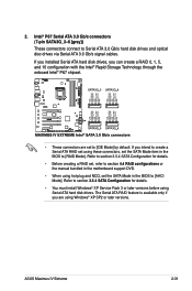
... hot-plug and NCQ, set the SATA Mode item in the motherboard support DVD. • When using Windows® XP SP2 or later versions. ASUS Maximus IV Extreme 2-31 Intel® P67 Serial ATA 3.0 Gb/s connectors (7-pin SATA3G_3-6 [gray]) These connectors connect to create a Serial ATA RAID set using Serial ATA hard disk drives. If...
... hot-plug and NCQ, set the SATA Mode item in the motherboard support DVD. • When using Windows® XP SP2 or later versions. ASUS Maximus IV Extreme 2-31 Intel® P67 Serial ATA 3.0 Gb/s connectors (7-pin SATA3G_3-6 [gray]) These connectors connect to create a Serial ATA RAID set using Serial ATA hard disk drives. If...


