
User Manual
Page 4
...heatsink and fan assembly installation 2-43 2.3.4 DIMM installation 2-45 2.3.5 Motherboard installation 2-46 2.3.6 ATX Power connection 2-48 2.3.7 SATA device connection 2-49 2.3.8 Front I/O Connector 2-50 2.3.9 Expension ... off the computer 2-57 Chapter 3: BIOS setup 3.1 Knowing BIOS 3-1 3.2 BIOS setup program 3-1 3.2.1 EZ Mode 3-2 3.2.2 Advanced Mode 3-3 3.3 Extreme Tweaker menu 3-5 3.4 Main menu 3-14 3.4.1 System Language [English 3-14 3.4.2 System Date [Day xx/xx/xxxx 3-14 3.4.3 System Time [xx... Connect 3-28 3.5.9 LED Control 3-28 3.6 Monitor menu 3-30 3.7 Boot menu 3-35 iv
...heatsink and fan assembly installation 2-43 2.3.4 DIMM installation 2-45 2.3.5 Motherboard installation 2-46 2.3.6 ATX Power connection 2-48 2.3.7 SATA device connection 2-49 2.3.8 Front I/O Connector 2-50 2.3.9 Expension ... off the computer 2-57 Chapter 3: BIOS setup 3.1 Knowing BIOS 3-1 3.2 BIOS setup program 3-1 3.2.1 EZ Mode 3-2 3.2.2 Advanced Mode 3-3 3.3 Extreme Tweaker menu 3-5 3.4 Main menu 3-14 3.4.1 System Language [English 3-14 3.4.2 System Date [Day xx/xx/xxxx 3-14 3.4.3 System Time [xx... Connect 3-28 3.5.9 LED Control 3-28 3.6 Monitor menu 3-30 3.7 Boot menu 3-35 iv
User Manual
Page 17
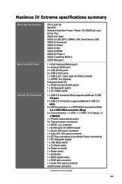
...ASUS Q-Connector ASUS Q-Shield ASUS Q-Slot ASUS Q-DIMM ASUS EZ Flash 2 ASUS CrashFree BIOS 3 ASUS MyLogo 2 1 x PS/2 Keyboard/Mouse port 2 x External SATA ports 2 x LAN (RJ45) ports 8 x USB 3.0/2.0 ports 1 x USB 2.0/1.1 ports (also for ROG Connect) 1 x S/PDIF Out (Optical) 8-channel Audio I /O Connectors CPU Level Up MemOK! Maximus IV Extreme... points 3 x Thermal sensor connectors 1 x SPDIF_out connector 1 x En/Dis-able Clr CMOS header 1 x 24-pin ATX power connector 1 x 8-pin ATX 12V power connector 2 x EZ Plug connectors (4-pin Molex Power connectors) 1 x RC Bluetooth header 1 x LN2 Mode ...
...ASUS Q-Connector ASUS Q-Shield ASUS Q-Slot ASUS Q-DIMM ASUS EZ Flash 2 ASUS CrashFree BIOS 3 ASUS MyLogo 2 1 x PS/2 Keyboard/Mouse port 2 x External SATA ports 2 x LAN (RJ45) ports 8 x USB 3.0/2.0 ports 1 x USB 2.0/1.1 ports (also for ROG Connect) 1 x S/PDIF Out (Optical) 8-channel Audio I /O Connectors CPU Level Up MemOK! Maximus IV Extreme... points 3 x Thermal sensor connectors 1 x SPDIF_out connector 1 x En/Dis-able Clr CMOS header 1 x 24-pin ATX power connector 1 x 8-pin ATX 12V power connector 2 x EZ Plug connectors (4-pin Molex Power connectors) 1 x RC Bluetooth header 1 x LN2 Mode ...
User Manual
Page 18
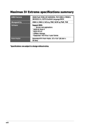
xviii Drivers and applications * ASUS AI Suite II * ROG CPU-Z * 3DMark Vantage * Kaspersky® Anti-Virus 1-year license Extended ATX Form Factor, 12"x 10.6" (30.5cm x 26.9cm) *Specifications are subject to change without notice. Maximus IV Extreme specifications summary BIOS Features Manageability Software Form Factor 32Mb Flash ROM, EFI AMI BIOS, PnP, DMI2.0, WfM2.0, SM BIOS 2.5, ACPI2.0a Multi-Language BIOS WfM2.0, DMI2.0, WOL by PME, WOR by PME, PXE Support DVD: -
xviii Drivers and applications * ASUS AI Suite II * ROG CPU-Z * 3DMark Vantage * Kaspersky® Anti-Virus 1-year license Extended ATX Form Factor, 12"x 10.6" (30.5cm x 26.9cm) *Specifications are subject to change without notice. Maximus IV Extreme specifications summary BIOS Features Manageability Software Form Factor 32Mb Flash ROM, EFI AMI BIOS, PnP, DMI2.0, WfM2.0, SM BIOS 2.5, ACPI2.0a Multi-Language BIOS WfM2.0, DMI2.0, WOL by PME, WOR by PME, PXE Support DVD: -
User Manual
Page 33
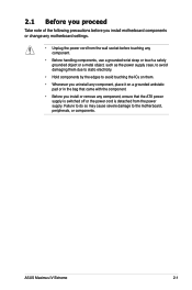
ASUS Maximus IV Extreme 2-1 Failure to do so may cause severe damage to avoid touching the ICs on them due to static electricity. • Hold components by the edges ... it on a grounded antistatic pad or in the bag that came with the component. • Before you install or remove any component, ensure that the ATX power supply is switched off or the power cord is detached from the power supply.
ASUS Maximus IV Extreme 2-1 Failure to do so may cause severe damage to avoid touching the ICs on them due to static electricity. • Hold components by the edges ... it on a grounded antistatic pad or in the bag that came with the component. • Before you install or remove any component, ensure that the ATX power supply is switched off or the power cord is detached from the power supply.
User Manual
Page 70
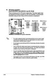
... a fully configured system, we recommend that complies with 1000W power or above to the Recommended Power Supply Wattage Calculator at http://support.asus.com/PowerSupplyCalculator/PSCalculator. The power supply plugs are for your system, refer to ensure the system stability. 2-38 Chapter 2: Hardware information... recommended when configuring a system with more high-end PCI Express x16 cards, use a power supply unit (PSU) that you use a PSU with ATX 12 V Specification 2.0 (or later version) and provides a minimum power of a PSU with a higher power output is inadequate. • If...
... a fully configured system, we recommend that complies with 1000W power or above to the Recommended Power Supply Wattage Calculator at http://support.asus.com/PowerSupplyCalculator/PSCalculator. The power supply plugs are for your system, refer to ensure the system stability. 2-38 Chapter 2: Hardware information... recommended when configuring a system with more high-end PCI Express x16 cards, use a power supply unit (PSU) that you use a PSU with ATX 12 V Specification 2.0 (or later version) and provides a minimum power of a PSU with a higher power output is inadequate. • If...
User Manual
Page 71
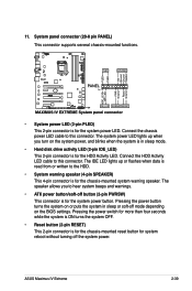
.... • System power LED (2-pin PLED) This 2-pin connector is read from or written to hear system beeps and warnings. • ATX power button/soft-off the system power. ASUS Maximus IV Extreme 2-39 The system power LED lights up or flashes when data is for the chassis-mounted system warning speaker. The speaker allows...
.... • System power LED (2-pin PLED) This 2-pin connector is read from or written to hear system beeps and warnings. • ATX power button/soft-off the system power. ASUS Maximus IV Extreme 2-39 The system power LED lights up or flashes when data is for the chassis-mounted system warning speaker. The speaker allows...
User Manual
Page 80
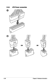
2.3.6 1 ATX Power connection 2 OR OR 2-48 Chapter 2: Hardware information
2.3.6 1 ATX Power connection 2 OR OR 2-48 Chapter 2: Hardware information
User Manual
Page 88
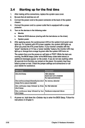
...turned on the devices in Chapter 3. 2-56 Chapter 2: Hardware information Turn on the power, the system may light up when you press the ATX power button. For systems with the last device on self tests or POST. Check the jumper settings and connections or call your monitor complies with... a surge protector. 5. External SCSI devices (starting with ATX power supplies, the system LED lights up or change from the time you do not see anything within 30 seconds from orange to a power ...
...turned on the devices in Chapter 3. 2-56 Chapter 2: Hardware information Turn on the power, the system may light up when you press the ATX power button. For systems with the last device on self tests or POST. Check the jumper settings and connections or call your monitor complies with... a surge protector. 5. External SCSI devices (starting with ATX power supplies, the system LED lights up or change from the time you do not see anything within 30 seconds from orange to a power ...

User Manual
Page 119
.... [Enabled] Enables the PCIE devices to set the iROG Time Keeper operation mode. Configuration options: [Last State] [Disabled] [Enabled] ASUS Maximus IV Extreme 3-27 This feature requires an ATX power supply that provides at least 1A on the system. Power On By PS/2 Keyboard [Disabled] [Disabled] Disables the Power On by... turn on the system. [Power Key] Sets Power key on the PS/2 keyboard to turn on the +5VSB lead. This feature requires an ATX power supply that provides at least 1A on the +5VSB lead. Power On By RTC [Disabled] [Disabled] Disables RTC to generate a wake ...
.... [Enabled] Enables the PCIE devices to set the iROG Time Keeper operation mode. Configuration options: [Last State] [Disabled] [Enabled] ASUS Maximus IV Extreme 3-27 This feature requires an ATX power supply that provides at least 1A on the system. Power On By PS/2 Keyboard [Disabled] [Disabled] Disables the Power On by... turn on the system. [Power Key] Sets Power key on the PS/2 keyboard to turn on the +5VSB lead. This feature requires an ATX power supply that provides at least 1A on the +5VSB lead. Power On By RTC [Disabled] [Disabled] Disables RTC to generate a wake ...

