M5A97 R2.0 User's Manual
Page 1
M5A97 R2.0 Motherboard
M5A97 R2.0 Motherboard
M5A97 R2.0 User's Manual
Page 3
... Power connection 2-9 2.1.6 SATA device connection 2-10 2.1.7 Expansion Card installation 2-11 2.2 BIOS update utility 2-12 2.2.1 USB BIOS Flashback 2-12 2.3 Motherboard rear and audio connections 2-13 iii Contents Safety information...vi About this guide...vii M5A97 R2.0 specifications summary ix Package contents...xii Installation tools and components xiii Product introduction 1.1 Special features 1-1 1.1.1 Product highlights 1-1 1.1.2 DIP...
... Power connection 2-9 2.1.6 SATA device connection 2-10 2.1.7 Expansion Card installation 2-11 2.2 BIOS update utility 2-12 2.2.1 USB BIOS Flashback 2-12 2.3 Motherboard rear and audio connections 2-13 iii Contents Safety information...vi About this guide...vii M5A97 R2.0 specifications summary ix Package contents...xii Installation tools and components xiii Product introduction 1.1 Special features 1-1 1.1.1 Product highlights 1-1 1.1.2 DIP...

M5A97 R2.0 User's Manual
Page 6
... system before using , contact your dealer immediately. • To avoid short circuits, keep paper clips, screws, and staples away from the motherboard, ensure that came with the product, contact a qualified service technician or your retailer. Operation safety • Before installing the... motherboard and adding devices on a stable surface. • If you are unplugged. • Seek professional assistance before you detect any damage, contact your ...
... system before using , contact your dealer immediately. • To avoid short circuits, keep paper clips, screws, and staples away from the motherboard, ensure that came with the product, contact a qualified service technician or your retailer. Operation safety • Before installing the... motherboard and adding devices on a stable surface. • If you are unplugged. • Seek professional assistance before you detect any damage, contact your ...

M5A97 R2.0 User's Manual
Page 7
... Installation This chapter lists the hardware setup procedures that you need when installing and configuring the motherboard. It includes description of the switches, jumpers, and connectors on ASUS hardware and software products. These documents are also provided. • Chapter 4: Software support .... • Chapter 6: Multiple GPU technology support This chapter describes how to the ASUS contact information. 2. Detailed descriptions of the BIOS parameters are not part of the motherboard and the new technology it supports. Refer to install and configure multiple AMD®...
... Installation This chapter lists the hardware setup procedures that you need when installing and configuring the motherboard. It includes description of the switches, jumpers, and connectors on ASUS hardware and software products. These documents are also provided. • Chapter 4: Software support .... • Chapter 6: Multiple GPU technology support This chapter describes how to the ASUS contact information. 2. Detailed descriptions of the BIOS parameters are not part of the motherboard and the new technology it supports. Refer to install and configure multiple AMD®...

M5A97 R2.0 User's Manual
Page 9
M5A97 R2.0 specifications summary CPU Chipset System Bus Memory Expansion slots Multi-GPU ...174; Quad-GPU CrossFireXTM Technology AMD® SB950 Chipset: - 6 x Serial ATA 6.0Gb/s ports with 8GB or above DIMMs. ASUS will update the memory QVL once the DIMMs are available in the market. • Due to CPU spec, AMD 100 Series CPUs ...a maximum of 4GB capacity or more, Windows® 32-bit operating system may only recognize less than 3GB. With ASUS design, this motherboard can be supported with RAID 0, 1, 5, 10 Realtek® 8111F Gigabit LAN controller Realtek 887 8-channel High Definition ...
M5A97 R2.0 specifications summary CPU Chipset System Bus Memory Expansion slots Multi-GPU ...174; Quad-GPU CrossFireXTM Technology AMD® SB950 Chipset: - 6 x Serial ATA 6.0Gb/s ports with 8GB or above DIMMs. ASUS will update the memory QVL once the DIMMs are available in the market. • Due to CPU spec, AMD 100 Series CPUs ...a maximum of 4GB capacity or more, Windows® 32-bit operating system may only recognize less than 3GB. With ASUS design, this motherboard can be supported with RAID 0, 1, 5, 10 Realtek® 8111F Gigabit LAN controller Realtek 887 8-channel High Definition ...
M5A97 R2.0 User's Manual
Page 12
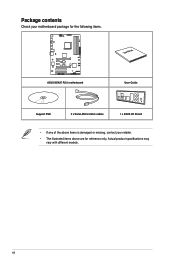
xii Actual product specifications may vary with different models. Package contents Check your motherboard package for the following items. M5A97 R2.0 ASUS M5A97 R2.0 motherboard User Manual User Guide Support DVD 2 x Serial ATA 6.0 Gb/s cables 1 x ASUS I/O Shield • If any of the above items is damaged or missing, contact your retailer. • The illustrated items above are for reference only.
xii Actual product specifications may vary with different models. Package contents Check your motherboard package for the following items. M5A97 R2.0 ASUS M5A97 R2.0 motherboard User Manual User Guide Support DVD 2 x Serial ATA 6.0 Gb/s cables 1 x ASUS I/O Shield • If any of the above items is damaged or missing, contact your retailer. • The illustrated items above are for reference only.

M5A97 R2.0 User's Manual
Page 13
xiii Installation tools and components 1 bag of screws Philips (cross) screwdriver PC chassis Power supply unit AMD AM3+ CPU AMD AM3+ compatible CPU Fan DIMM SATA hard disk drive SATA optical disc drive (optional) Graphics card (optional) The tools and components in the table above are not included in the motherboard package.
xiii Installation tools and components 1 bag of screws Philips (cross) screwdriver PC chassis Power supply unit AMD AM3+ CPU AMD AM3+ compatible CPU Fan DIMM SATA hard disk drive SATA optical disc drive (optional) Graphics card (optional) The tools and components in the table above are not included in the motherboard package.
M5A97 R2.0 User's Manual
Page 15
...down screen resolution to provide excellent system performance and overclocking capabilities. DDR3 2133(O.C.)/1866/1600/1333/1066 support This motherboard supports DDR3 memory that features data transfer rates of the latest 3D graphics, multimedia, and Internet applications. AMD...within AMD Vision Engine Control Center. Complete USB 3.0 integration This motherboard offers you the strategic USB 3.0 accessibility for a cool and quiet operating environment. M5A97 R2.0 1-1 Front Panel USB 3.0 Support ASUS provides standardized USB 3.0 front panel support which monitors system operation and...
...down screen resolution to provide excellent system performance and overclocking capabilities. DDR3 2133(O.C.)/1866/1600/1333/1066 support This motherboard supports DDR3 memory that features data transfer rates of the latest 3D graphics, multimedia, and Internet applications. AMD...within AMD Vision Engine Control Center. Complete USB 3.0 integration This motherboard offers you the strategic USB 3.0 accessibility for a cool and quiet operating environment. M5A97 R2.0 1-1 Front Panel USB 3.0 Support ASUS provides standardized USB 3.0 front panel support which monitors system operation and...

M5A97 R2.0 User's Manual
Page 18
... products through product design and innovation to reduce carbon footprint of the product and thus mitigate environmental impacts. Profile The motherboard features the ASUS O.C. ASUS O.C. Precision Tweaker 2 Allows you to fine-tune the VCore / VDDNB voltage in 0.00625V steps and DRAM voltage ...ultimate overclocking configuration. 1.1.6 Other Features ErP ready The motherboard is in regards to energy consumptions. ASUS MyLogo 2™ Turn your favorite photos into 256-color boot logos to personalize your favorite settings. ASUS EZ Flash 2 ASUS EZ Flash 2 is a user-friendly utility that...
... products through product design and innovation to reduce carbon footprint of the product and thus mitigate environmental impacts. Profile The motherboard features the ASUS O.C. ASUS O.C. Precision Tweaker 2 Allows you to fine-tune the VCore / VDDNB voltage in 0.00625V steps and DRAM voltage ...ultimate overclocking configuration. 1.1.6 Other Features ErP ready The motherboard is in regards to energy consumptions. ASUS MyLogo 2™ Turn your favorite photos into 256-color boot logos to personalize your favorite settings. ASUS EZ Flash 2 ASUS EZ Flash 2 is a user-friendly utility that...
M5A97 R2.0 User's Manual
Page 19
...antistatic pad or in the bag that came with the component. • Before you install motherboard components or change any motherboard settings. • Unplug the power cord from the wall socket before touching any component, ...switch off the ATX power supply and detach its power cord. 1.2 Motherboard overview 1.2.1 Before you proceed Take note of the following precautions before you install or remove any component. &#... electricity. • Hold components by the edges to the motherboard, peripherals, or components. Chapter 1 M5A97 R2.0 1-5
...antistatic pad or in the bag that came with the component. • Before you install motherboard components or change any motherboard settings. • Unplug the power cord from the wall socket before touching any component, ...switch off the ATX power supply and detach its power cord. 1.2 Motherboard overview 1.2.1 Before you proceed Take note of the following precautions before you install or remove any component. &#... electricity. • Hold components by the edges to the motherboard, peripherals, or components. Chapter 1 M5A97 R2.0 1-5

M5A97 R2.0 User's Manual
Page 20
1.2.2 Motherboard layout 1 2 3 1 4 22.9cm(9.0in) KBMS EATX12V EPU CHA_FAN2 CPU_FAN CHA_FAN3 DDR3 DIMM_A1 (64bit, 240-pin module) DDR3 DIMM_A2 (64bit, 240-pin module) DDR3 DIMM_B1 (64bit, ... AM3+ USB34 2 LAN1_USB12 30.5cm(12.0in) CHA_FAN1 AUDIO AMD® 970 RTL 8111F Super I/O TPU PCIEX16_1 PCIEX1_1 ICS 9LPRS477 Lithium Cell CMOS Power PCIEX1_2 M5A97 R2.0 PCIEX16_2 64Mb BIOS DirectKey ASM 1042 AMD® SB950 SATA6G_6 SATA6G_5 USB3_34 PCI1 SATA6G_2 SATA6G_4 ALC 887 SB_PWR PCI2 CLRTC DRCT SPDIF_OUT COM1 TPM USB1314...
1.2.2 Motherboard layout 1 2 3 1 4 22.9cm(9.0in) KBMS EATX12V EPU CHA_FAN2 CPU_FAN CHA_FAN3 DDR3 DIMM_A1 (64bit, 240-pin module) DDR3 DIMM_A2 (64bit, 240-pin module) DDR3 DIMM_B1 (64bit, ... AM3+ USB34 2 LAN1_USB12 30.5cm(12.0in) CHA_FAN1 AUDIO AMD® 970 RTL 8111F Super I/O TPU PCIEX16_1 PCIEX1_1 ICS 9LPRS477 Lithium Cell CMOS Power PCIEX1_2 M5A97 R2.0 PCIEX16_2 64Mb BIOS DirectKey ASM 1042 AMD® SB950 SATA6G_6 SATA6G_5 USB3_34 PCI1 SATA6G_2 SATA6G_4 ALC 887 SB_PWR PCI2 CLRTC DRCT SPDIF_OUT COM1 TPM USB1314...
M5A97 R2.0 User's Manual
Page 22
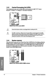
...the connectors on a DDR2 DIMM socket. The figure illustrates the location of the DDR3 DIMM sockets: DIMM_A1 DIMM_A2 DIMM_B1 DIMM_B2 Chapter 1 M5A97 R2.0 M5A97 R2.0 240-pin DDR3 DIMM sockets 1-8 Chapter 1: Product introduction Ensure that all power cables are developed for the AM3+ socket. The...orientation. DO NOT force the CPU into the socket to prevent installation on the socket and damaging the CPU! 1.2.4 System memory This motherboard comes with four Double Data Rate 3 (DDR3) Dual Inline Memory Modules (DIMM) sockets. DDR3 modules are unplugged before installing the ...
...the connectors on a DDR2 DIMM socket. The figure illustrates the location of the DDR3 DIMM sockets: DIMM_A1 DIMM_A2 DIMM_B1 DIMM_B2 Chapter 1 M5A97 R2.0 M5A97 R2.0 240-pin DDR3 DIMM sockets 1-8 Chapter 1: Product introduction Ensure that all power cables are developed for the AM3+ socket. The...orientation. DO NOT force the CPU into the socket to prevent installation on the socket and damaging the CPU! 1.2.4 System memory This motherboard comes with four Double Data Rate 3 (DDR3) Dual Inline Memory Modules (DIMM) sockets. DDR3 modules are unplugged before installing the ...

M5A97 R2.0 User's Manual
Page 23
...• Due to support a full memory load (4 DIMMs) or overclocking condition. • Visit the ASUS website at www.asus.com for overclocking may operate at a higher frequency, refer to section 3.4 Ai Tweaker menu for manual ...memory frequency adjustment. • For system stability, use of memory, we recommend that you want to install 4GB or more memory on the motherboard. • This motherboard.... • Memory module with the same CAS latency. M5A97 R2.0 1-9 Chapter 1
...• Due to support a full memory load (4 DIMMs) or overclocking condition. • Visit the ASUS website at www.asus.com for overclocking may operate at a higher frequency, refer to section 3.4 Ai Tweaker menu for manual ...memory frequency adjustment. • For system stability, use of memory, we recommend that you want to install 4GB or more memory on the motherboard. • This motherboard.... • Memory module with the same CAS latency. M5A97 R2.0 1-9 Chapter 1
M5A97 R2.0 User's Manual
Page 28
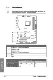
Failure to do so may cause you physical injury and damage motherboard components. 1 2 3 M5A97 R2.0 4 5 6 Slot No. 1 2 3 4 5 6 Slot Description PCIe 2.0 x16_1 slot [blue] (at x16 mode) PCIe 2.0 x1_1 slot PCIe 2.0 x1_2 slot PCIe 2.0 x16_2 slot [black] (at x4 mode) PCI 1 PCI 2 VGA configuration Single VGA/PCIe card Dual VGA/PCIe card PCI Express operating mode PCIe 2.0 x16_1 x16 (Recommend for single VGA) x16 PCIe 2.0 x16_2 N/A x4 1-14 Chapter 1: Product introduction Chapter 1 1.2.5 Expansion slots Unplug the power cord before adding or removing expansion cards.
Failure to do so may cause you physical injury and damage motherboard components. 1 2 3 M5A97 R2.0 4 5 6 Slot No. 1 2 3 4 5 6 Slot Description PCIe 2.0 x16_1 slot [blue] (at x16 mode) PCIe 2.0 x1_1 slot PCIe 2.0 x1_2 slot PCIe 2.0 x16_2 slot [black] (at x4 mode) PCI 1 PCI 2 VGA configuration Single VGA/PCIe card Dual VGA/PCIe card PCI Express operating mode PCIe 2.0 x16_1 x16 (Recommend for single VGA) x16 PCIe 2.0 x16_2 N/A x4 1-14 Chapter 1: Product introduction Chapter 1 1.2.5 Expansion slots Unplug the power cord before adding or removing expansion cards.

M5A97 R2.0 User's Manual
Page 29
...- - - - - On Chip USB 2 - - IRQ assignments for better thermal environment. shared - shared - - - Chapter 1 M5A97 R2.0 1-15 Realtek 8111F (LAN) - - - - On Chip USB 3 - - shared - - - - - HD Audio shared...performance. • We recommend that you provide sufficient power when running CrossFireX™ mode. • Connect a chassis fan to the motherboard connector labeled CHA_FAN1/2/3 when using multiple graphics cards for this motherboard A B C D E F G H PCIe x16_1 - - - - PCIe x16_2 - - - - shared - - - ...
...- - - - - On Chip USB 2 - - IRQ assignments for better thermal environment. shared - shared - - - Chapter 1 M5A97 R2.0 1-15 Realtek 8111F (LAN) - - - - On Chip USB 3 - - shared - - - - - HD Audio shared...performance. • We recommend that you provide sufficient power when running CrossFireX™ mode. • Connect a chassis fan to the motherboard connector labeled CHA_FAN1/2/3 when using multiple graphics cards for this motherboard A B C D E F G H PCIe x16_1 - - - - PCIe x16_2 - - - - shared - - - ...
M5A97 R2.0 User's Manual
Page 31
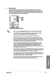
... DIMMs that are incompatible with ones recommended in the Memory QVL (Qualified Vendors Lists) in this user manual or on the ASUS website at www.asus.com after turning on the computer. Turn off the computer and unplug the power cord for about 30 seconds for the system...when the DIMM is tested. Replace the DIMMs with the motherboard may cause system boot failure, and the DRAM_LED near the MemOK! switch to begin automatic memory compatibility tuning for the exact location of failsafe settings. Chapter 1 M5A97 R2.0 1-17 switch until the DRAM_LED starts blinking to boot and...
... DIMMs that are incompatible with ones recommended in the Memory QVL (Qualified Vendors Lists) in this user manual or on the ASUS website at www.asus.com after turning on the computer. Turn off the computer and unplug the power cord for about 30 seconds for the system...when the DIMM is tested. Replace the DIMMs with the motherboard may cause system boot failure, and the DRAM_LED near the MemOK! switch to begin automatic memory compatibility tuning for the exact location of failsafe settings. Chapter 1 M5A97 R2.0 1-17 switch until the DRAM_LED starts blinking to boot and...
M5A97 R2.0 User's Manual
Page 34
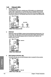
...you should shut down the system and unplug the power cable before removing or plugging in any motherboard component. SB_PWR M5A97 R2.0 ON OFF Standby Power Powered Off M5A97 R2.0 Onboard LED 2. This user-friendly design provides an intuitional way to the error device will...LED. Chapter 1 1-20 M5A97 R2.0 FLBK_LED M5A97 R2.0 FLBK LED Chapter 1: Product introduction DRAM LED M5A97 R2.0 M5A97 R2.0 DRAM LED 3. BIOS Flashback LED (FLBK_LED) The FLBK LED lights when the USB Flashback button is ON, in sleep mode, or in sequence during motherboard booting process. DRAM LED ...
...you should shut down the system and unplug the power cable before removing or plugging in any motherboard component. SB_PWR M5A97 R2.0 ON OFF Standby Power Powered Off M5A97 R2.0 Onboard LED 2. This user-friendly design provides an intuitional way to the error device will...LED. Chapter 1 1-20 M5A97 R2.0 FLBK_LED M5A97 R2.0 FLBK LED Chapter 1: Product introduction DRAM LED M5A97 R2.0 M5A97 R2.0 DRAM LED 3. BIOS Flashback LED (FLBK_LED) The FLBK LED lights when the USB Flashback button is ON, in sleep mode, or in sequence during motherboard booting process. DRAM LED ...

M5A97 R2.0 User's Manual
Page 35
...CPU FAN PWR GND CHA FAN PWM CHA FAN IN CHA FAN PWR GND M5A97 R2.0 CHA_FAN1 GND CHA FAN PWR CHA FAN IN CHA FAN PWM M5A97 R2.0 Fan connectors DO NOT forget to connect the fan cables to the motherboard connector labeled CHA_FAN1/2/3 for better thermal environment. 2. DO NOT place jumper ...caps on the motherboard, ensuring that the black wire of each cable matches the ground pin of maximum 1A (12 W) fan power. • Only the CPU_FAN and CHA_FAN1/2/3 connectors support the ASUS Fan Xpert feature. • If you install two VGA cards, ...
...CPU FAN PWR GND CHA FAN PWM CHA FAN IN CHA FAN PWR GND M5A97 R2.0 CHA_FAN1 GND CHA FAN PWR CHA FAN IN CHA FAN PWM M5A97 R2.0 Fan connectors DO NOT forget to connect the fan cables to the motherboard connector labeled CHA_FAN1/2/3 for better thermal environment. 2. DO NOT place jumper ...caps on the motherboard, ensuring that the black wire of each cable matches the ground pin of maximum 1A (12 W) fan power. • Only the CPU_FAN and CHA_FAN1/2/3 connectors support the ASUS Fan Xpert feature. • If you install two VGA cards, ...

M5A97 R2.0 User's Manual
Page 37
... RSATA_TXN3 GND RSATA_RXN3 RSATA_RXP3 GND GND RSATA_TXP1 RSATA_TXN1 GND RSATA_RXN1 RSATA_RXP1 GND M5A97 R2.0 SATA6G_1 SATA6G_3 M5A97 R2.0 SATA 6.0Gb/s connectors • These connectors are set the SATA Mode in the BIOS to section 5.1 RAID configurations or the manual bundled in the motherboard support DVD. • When using Serial ATA hard disk drives. Refer to...
... RSATA_TXN3 GND RSATA_RXN3 RSATA_RXP3 GND GND RSATA_TXP1 RSATA_TXN1 GND RSATA_RXN1 RSATA_RXP1 GND M5A97 R2.0 SATA6G_1 SATA6G_3 M5A97 R2.0 SATA 6.0Gb/s connectors • These connectors are set the SATA Mode in the BIOS to section 5.1 RAID configurations or the manual bundled in the motherboard support DVD. • When using Serial ATA hard disk drives. Refer to...

M5A97 R2.0 User's Manual
Page 40
...M5A97 R2.0 M5A97 R2.0 USB3.0 Front panel connector The USB 3.0 module is purchased separately. 9. Front panel audio connector (10-1 pin AAFP) This connector is for a chassis-mounted front panel audio I/O module that you connect a high-definition front panel audio module to this connector to avail of the motherboard...module is purchased separately. 1-26 Chapter 1: Product introduction Chapter 1 If your chassis support customized front panel installation, with ASUS USB 3.0 header, you want to connect a high definition front panel audio module to this connector. 8. Connect one ...
...M5A97 R2.0 M5A97 R2.0 USB3.0 Front panel connector The USB 3.0 module is purchased separately. 9. Front panel audio connector (10-1 pin AAFP) This connector is for a chassis-mounted front panel audio I/O module that you connect a high-definition front panel audio module to this connector to avail of the motherboard...module is purchased separately. 1-26 Chapter 1: Product introduction Chapter 1 If your chassis support customized front panel installation, with ASUS USB 3.0 header, you want to connect a high definition front panel audio module to this connector. 8. Connect one ...


