M5A97 R2.0 User's Manual
Page 3
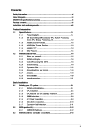
...M5A97 R2.0 specifications summary ix Package contents...xii Installation tools and components xiii Product introduction 1.1 Special features 1-1 1.1.1 Product highlights 1-1 1.1.2 DIP (Dual Intelligent Processors) - TPU (TurboV Processing Unit) & EPU (Energy Processing Unit 1-2 1.1.3 ASUS Exclusive Features 1-2 1.1.4 ASUS Quiet Thermal Solution 1-3 1.1.5 ASUS...assembly installation 2-5 2.1.4 DIMM installation 2-8 2.1.5 ATX Power connection 2-9 2.1.6 SATA device connection 2-10 2.1.7 Expansion Card installation 2-11 2.2 BIOS update utility 2-12 2.2.1 USB BIOS Flashback ...
...M5A97 R2.0 specifications summary ix Package contents...xii Installation tools and components xiii Product introduction 1.1 Special features 1-1 1.1.1 Product highlights 1-1 1.1.2 DIP (Dual Intelligent Processors) - TPU (TurboV Processing Unit) & EPU (Energy Processing Unit 1-2 1.1.3 ASUS Exclusive Features 1-2 1.1.4 ASUS Quiet Thermal Solution 1-3 1.1.5 ASUS...assembly installation 2-5 2.1.4 DIMM installation 2-8 2.1.5 ATX Power connection 2-9 2.1.6 SATA device connection 2-10 2.1.7 Expansion Card installation 2-11 2.2 BIOS update utility 2-12 2.2.1 USB BIOS Flashback ...

M5A97 R2.0 User's Manual
Page 6
.... • Avoid dust, humidity, and temperature extremes. If you add a device. • Before connecting or removing signal cables from the motherboard, ensure that your power supply is broken, do not try to fix it , carefully read all the manuals that came with the...installing the motherboard and adding devices on a stable surface. • If you are connected. These devices could interrupt the grounding circuit. • Ensure that all cables are correctly connected and the power cables are unplugged. • Seek professional assistance before the signal cables are using,...
.... • Avoid dust, humidity, and temperature extremes. If you add a device. • Before connecting or removing signal cables from the motherboard, ensure that your power supply is broken, do not try to fix it , carefully read all the manuals that came with the...installing the motherboard and adding devices on a stable surface. • If you are connected. These devices could interrupt the grounding circuit. • Ensure that all cables are correctly connected and the power cables are unplugged. • Seek professional assistance before the signal cables are using,...
M5A97 R2.0 User's Manual
Page 15
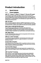
... the higher bandwidth requirements of the latest plug and play connectivity solution at speed up to 4800MT/s via HyperTransport™ ... AMD's CrossFireX™ boosts image quality along with less power consumption. AMD® 970 Chipset AMD® 970 Chipset.... This motherboard also supports AMD® CPUs in the new 32nm manufacturing process. M5A97 R2.0 1-1 Product introduction 1.1 Special features 1 1.1.1 Product highlights AMD® FX™... boost system performance. Front Panel USB 3.0 Support ASUS provides standardized USB 3.0 front panel support which monitors...
... the higher bandwidth requirements of the latest plug and play connectivity solution at speed up to 4800MT/s via HyperTransport™ ... AMD's CrossFireX™ boosts image quality along with less power consumption. AMD® 970 Chipset AMD® 970 Chipset.... This motherboard also supports AMD® CPUs in the new 32nm manufacturing process. M5A97 R2.0 1-1 Product introduction 1.1 Special features 1 1.1.1 Product highlights AMD® FX™... boost system performance. Front Panel USB 3.0 Support ASUS provides standardized USB 3.0 front panel support which monitors...

M5A97 R2.0 User's Manual
Page 16
...TurboV Processing Unit) & EPU (Energy Processing Unit) TPU Unleash your performance with your network programs. It allows you to automatically connect to a PPPoE network for fast, yet stable clock speeds, and the TurboV gives you the freedom to adjust CPU frequencies and...accelerates data speeds for compatible USB 3.0 peripherals without the need for critical PC components in real-time-helping save power and money! 1.1.3 ASUS Exclusive Features MemOK! Ai Charger+ ASUS Ai Charger+, the latest Ai Charger* version, brings you can intelligently optimize the system for a more convenient online...
...TurboV Processing Unit) & EPU (Energy Processing Unit) TPU Unleash your performance with your network programs. It allows you to automatically connect to a PPPoE network for fast, yet stable clock speeds, and the TurboV gives you the freedom to adjust CPU frequencies and...accelerates data speeds for compatible USB 3.0 peripherals without the need for critical PC components in real-time-helping save power and money! 1.1.3 ASUS Exclusive Features MemOK! Ai Charger+ ASUS Ai Charger+, the latest Ai Charger* version, brings you can intelligently optimize the system for a more convenient online...

M5A97 R2.0 User's Manual
Page 20
... AMD® 970 RTL 8111F Super I/O TPU PCIEX16_1 PCIEX1_1 ICS 9LPRS477 Lithium Cell CMOS Power PCIEX1_2 M5A97 R2.0 PCIEX16_2 64Mb BIOS DirectKey ASM 1042 AMD® SB950 SATA6G_6 SATA6G_5 USB3_34 PCI1 SATA6G_2 SATA6G_4... ALC 887 SB_PWR PCI2 CLRTC DRCT SPDIF_OUT COM1 TPM USB1314 USB1112 USB910 FLBK_LED PANEL SATA6G_1 SATA6G_3 AAFP BIOS_FLBK 7 8 9 10 11 12 9 20 19 18 17 16 15 14 13 Refer to 1.2.9 Internal connectors and 2.3.1 Rear I/O connection...
... AMD® 970 RTL 8111F Super I/O TPU PCIEX16_1 PCIEX1_1 ICS 9LPRS477 Lithium Cell CMOS Power PCIEX1_2 M5A97 R2.0 PCIEX16_2 64Mb BIOS DirectKey ASM 1042 AMD® SB950 SATA6G_6 SATA6G_5 USB3_34 PCI1 SATA6G_2 SATA6G_4... ALC 887 SB_PWR PCI2 CLRTC DRCT SPDIF_OUT COM1 TPM USB1314 USB1112 USB910 FLBK_LED PANEL SATA6G_1 SATA6G_3 AAFP BIOS_FLBK 7 8 9 10 11 12 9 20 19 18 17 16 15 14 13 Refer to 1.2.9 Internal connectors and 2.3.1 Rear I/O connection...

M5A97 R2.0 User's Manual
Page 29
... (navy blue) for a PCI Express x16 graphics card to get better performance. • We recommend that you provide sufficient power when running CrossFireX™ mode. • Connect a chassis fan to the motherboard connector labeled CHA_FAN1/2/3 when using multiple graphics cards for this motherboard A B C D E F G H PCIe x16_1 - - - - shared - - Realtek 8111F (LAN) - - - - shared - - - Chapter 1 M5A97 R2.0 1-15
... (navy blue) for a PCI Express x16 graphics card to get better performance. • We recommend that you provide sufficient power when running CrossFireX™ mode. • Connect a chassis fan to the motherboard connector labeled CHA_FAN1/2/3 when using multiple graphics cards for this motherboard A B C D E F G H PCIe x16_1 - - - - shared - - Realtek 8111F (LAN) - - - - shared - - - Chapter 1 M5A97 R2.0 1-15

M5A97 R2.0 User's Manual
Page 35
... a Trusted Platform Module (TPM) system, which can securely store keys, digital certificates, passwords, and data. M5A97 R2.0 1-21 Chapter 1 CPU and chassis fan connectors (4-pin CPU_FAN, and 4-pin CHA_FAN1/2/3) Connect the fan cables to the fan connectors on the fan connectors. • The CPU_FAN connector supports a CPU ..., ensuring that the black wire of each cable matches the ground pin of maximum 1A (12 W) fan power. • Only the CPU_FAN and CHA_FAN1/2/3 connectors support the ASUS Fan Xpert feature. • If you install two VGA cards, we recommend that you plug the rear ...
... a Trusted Platform Module (TPM) system, which can securely store keys, digital certificates, passwords, and data. M5A97 R2.0 1-21 Chapter 1 CPU and chassis fan connectors (4-pin CPU_FAN, and 4-pin CHA_FAN1/2/3) Connect the fan cables to the fan connectors on the fan connectors. • The CPU_FAN connector supports a CPU ..., ensuring that the black wire of each cable matches the ground pin of maximum 1A (12 W) fan power. • Only the CPU_FAN and CHA_FAN1/2/3 connectors support the ASUS Fan Xpert feature. • If you install two VGA cards, we recommend that you plug the rear ...

M5A97 R2.0 User's Manual
Page 36
...DO NOT forget to install additional devices. The system may become unstable or may not boot up if the power is inadequate. • If you intend to connect the 4-pin / 8-pin ATX +12V power plug. The system may become unstable or may not boot up . • We recommend that you use... a PSU with 20-pin and 4-pin power plugs, ensure that the 20-pin power plug can provide at http://support.asus. 3. com/PowerSupplyCalculator/PSCalculator.aspx?SLanguage=en-us for an ATX power supply. EATX12V EATXPWR +12V DC +12V DC +12V DC +12V DC M5A97 R2.0 GND GND GND GND +3 Volts +12 Volts...
...DO NOT forget to install additional devices. The system may become unstable or may not boot up if the power is inadequate. • If you intend to connect the 4-pin / 8-pin ATX +12V power plug. The system may become unstable or may not boot up . • We recommend that you use... a PSU with 20-pin and 4-pin power plugs, ensure that the 20-pin power plug can provide at http://support.asus. 3. com/PowerSupplyCalculator/PSCalculator.aspx?SLanguage=en-us for an ATX power supply. EATX12V EATXPWR +12V DC +12V DC +12V DC +12V DC M5A97 R2.0 GND GND GND GND +3 Volts +12 Volts...

M5A97 R2.0 User's Manual
Page 39
... The IDE LED lights up when you to this connector. PWR Ground Reset Ground M5A97 R2.0 IDE_LED PWRSW RESET * Requires an ATX power supply M5A97 R2.0 System panel connector • System power LED (2-pin PLED) This 2-pin connector is for the chassis-mounted reset button for...+ IDE_LED- System panel connector (20-8 pin PANEL) This connector supports several chassis-mounted functions. Chapter 1 M5A97 R2.0 1-25 Connect the HDD Activity LED cable to hear system beeps and warnings. • ATX power button/soft-off button (2-pin PWRSW) This connector is for the system...
... The IDE LED lights up when you to this connector. PWR Ground Reset Ground M5A97 R2.0 IDE_LED PWRSW RESET * Requires an ATX power supply M5A97 R2.0 System panel connector • System power LED (2-pin PLED) This 2-pin connector is for the chassis-mounted reset button for...+ IDE_LED- System panel connector (20-8 pin PANEL) This connector supports several chassis-mounted functions. Chapter 1 M5A97 R2.0 1-25 Connect the HDD Activity LED cable to hear system beeps and warnings. • ATX power button/soft-off button (2-pin PWRSW) This connector is for the system...

M5A97 R2.0 User's Manual
Page 51
2.1.5 1 ATX Power connection 2 OR OR Chapter 2 ASUS M5A97 R2.0 2-9
2.1.5 1 ATX Power connection 2 OR OR Chapter 2 ASUS M5A97 R2.0 2-9

M5A97 R2.0 User's Manual
Page 59
... No memory detected No VGA detected Hardware component failure 7. System power 6. At power on sleep mode or soft-off mode regardless of the system chassis. 4. Chapter 2 ASUS M5A97 R2.0 2-17 2.4 Starting up for assistance. While the tests are off. 3. Check the jumper settings and connections or call your monitor complies with the last device on . Follow...
... No memory detected No VGA detected Hardware component failure 7. System power 6. At power on sleep mode or soft-off mode regardless of the system chassis. 4. Chapter 2 ASUS M5A97 R2.0 2-17 2.4 Starting up for assistance. While the tests are off. 3. Check the jumper settings and connections or call your monitor complies with the last device on . Follow...

M5A97 R2.0 User's Manual
Page 62
... section 3.9 Exit Menu for reference purposes only, and may not exactly match what you see on your screen. • Ensure that a USB mouse is connected to the default value. Do this option only if you failed to enter BIOS Setup using the BIOS Setup program. The BIOS screen include navigation.... • If the system fails to boot after POST: • Press ++ simultaneously. • Press the reset button on the system chassis. • Press the power button to turn the system off then back on how to ensure system compatibility and stability. Entering BIOS at startup To enter BIOS Setup at...
... section 3.9 Exit Menu for reference purposes only, and may not exactly match what you see on your screen. • Ensure that a USB mouse is connected to the default value. Do this option only if you failed to enter BIOS Setup using the BIOS Setup program. The BIOS screen include navigation.... • If the system fails to boot after POST: • Press ++ simultaneously. • Press the reset button on the system chassis. • Press the power button to turn the system off then back on how to ensure system compatibility and stability. Entering BIOS at startup To enter BIOS Setup at...

M5A97 R2.0 User's Manual
Page 81
ASUS M5A97 R2.0 3-21 Chapter 3 3.6 Monitor menu The Monitor menu displays the system temperature/power status, and allows you to display the detected temperatures. 3.6.2 VCORE Voltage, 3.3V Voltage, 5V Voltage, 12V Voltage, VDDA2.5V Voltage The onboard hardware monitor... not wish to change the fan settings. Select Ignore if you do not want to the motherboard, the field shows N/A. If the fan is not connected to detect this item. 3.6.3 CPU_FAN Speed [xxxx RPM] or [Ignore] / [N/A] CHA_FAN1/2/3 Speed [xxxx RPM] or [Ignore] / [N/A] The onboard hardware monitor automatically detects and...
ASUS M5A97 R2.0 3-21 Chapter 3 3.6 Monitor menu The Monitor menu displays the system temperature/power status, and allows you to display the detected temperatures. 3.6.2 VCORE Voltage, 3.3V Voltage, 5V Voltage, 12V Voltage, VDDA2.5V Voltage The onboard hardware monitor... not wish to change the fan settings. Select Ignore if you do not want to the motherboard, the field shows N/A. If the fan is not connected to detect this item. 3.6.3 CPU_FAN Speed [xxxx RPM] or [Ignore] / [N/A] CHA_FAN1/2/3 Speed [xxxx RPM] or [Ignore] / [N/A] The onboard hardware monitor automatically detects and...

M5A97 R2.0 User's Manual
Page 134
... this: 1. Chapter 5 5-2 Chapter 5: RAID configurations Install the SATA hard disks into the drive bays. 2. Enter the BIOS Setup during POST. 2. Connect a SATA power cable to [RAID Mode]. 4. For optimal performance, install identical drives of the same model and capacity when creating a disk array.... Connect the SATA signal cables. 3. Refer to Chapter 3 for a RAID configuration: 1. Save your changes, and then exit the BIOS Setup. ...
... this: 1. Chapter 5 5-2 Chapter 5: RAID configurations Install the SATA hard disks into the drive bays. 2. Enter the BIOS Setup during POST. 2. Connect a SATA power cable to [RAID Mode]. 4. For optimal performance, install identical drives of the same model and capacity when creating a disk array.... Connect the SATA signal cables. 3. Refer to Chapter 3 for a RAID configuration: 1. Save your changes, and then exit the BIOS Setup. ...

M5A97 R2.0 User's Manual
Page 144
... GPU support If your motherboard has more than two PCIEX16 slots, refer to the two graphics cards separately. 6. Connect two independent auxiliary power sources from the power supply to Chapter 1 in place. Ensure that the connector is firmly in this user manual for the locations of...8482; graphics cards The following pictures are properly seated on each graphics card. Ensure that the cards are for multi-graphics card installation. 3. Connect a VGA or a DVI cable to the goldfingers on the slots. 4. Prepare two CrossFireX-ready graphics cards. 2. Chapter 6 CrossFireX bridge...
... GPU support If your motherboard has more than two PCIEX16 slots, refer to the two graphics cards separately. 6. Connect two independent auxiliary power sources from the power supply to Chapter 1 in place. Ensure that the connector is firmly in this user manual for the locations of...8482; graphics cards The following pictures are properly seated on each graphics card. Ensure that the cards are for multi-graphics card installation. 3. Connect a VGA or a DVI cable to the goldfingers on the slots. 4. Prepare two CrossFireX-ready graphics cards. 2. Chapter 6 CrossFireX bridge...


