
User Manual
Page 6
The use of shielded cables for connection of the following measures: • Reorient or relocate the receiving antenna. • Increase the separation between the equipment and receiver. • Connect the ... in the Radio Interference Regulations of the Canadian Department of Chemicals) regulatory framework, we published the chemical substances in our products at ASUS REACH website at http://csr.asus.com/english/REACH.htm. Changes or modifications to this unit not expressly approved by one or more of the monitor to operate this...
The use of shielded cables for connection of the following measures: • Reorient or relocate the receiving antenna. • Increase the separation between the equipment and receiver. • Connect the ... in the Radio Interference Regulations of the Canadian Department of Chemicals) regulatory framework, we published the chemical substances in our products at ASUS REACH website at http://csr.asus.com/english/REACH.htm. Changes or modifications to this unit not expressly approved by one or more of the monitor to operate this...

User Manual
Page 7
...cord. vii Do not place the product in your retailer. If possible, disconnect all power cables are using the product, ensure all cables are correctly connected and the power cables are connected. If you are not sure about the voltage of the electrical outlet you ...technician or your area. If you add a device. • Before connecting or removing signal cables from the motherboard, ensure that the power cables for the devices are unplugged before the signal cables are not damaged. Safety information Electrical safety • To prevent electrical shock hazard, disconnect the...
...cord. vii Do not place the product in your retailer. If possible, disconnect all power cables are using the product, ensure all cables are correctly connected and the power cables are connected. If you are not sure about the voltage of the electrical outlet you ...technician or your area. If you add a device. • Before connecting or removing signal cables from the motherboard, ensure that the power cables for the devices are unplugged before the signal cables are not damaged. Safety information Electrical safety • To prevent electrical shock hazard, disconnect the...

User Manual
Page 13
...for the following items. User Manual ASUS M5A97 EVO motherboard User guide Support DVD 3 x Serial ATA 6.0 Gb/s cables 1 x 2-in the long line of ASUS quality motherboards! Thank you start installing the motherboard, and hardware devices on it another standout in -1 ASUS Q-Connector kit 1 x ASUS I/O Shield • If any ... your package with different models. The motherboard delivers a host of the above are for buying an ASUS® M5A97 EVO motherboard! Chapter 1 Chapter 1: Chapter 1 Product introduction 1.1 Welcome! ASUS M5A97 EVO 1-1 Before you for reference only.
...for the following items. User Manual ASUS M5A97 EVO motherboard User guide Support DVD 3 x Serial ATA 6.0 Gb/s cables 1 x 2-in the long line of ASUS quality motherboards! Thank you start installing the motherboard, and hardware devices on it another standout in -1 ASUS Q-Connector kit 1 x ASUS I/O Shield • If any ... your package with different models. The motherboard delivers a host of the above are for buying an ASUS® M5A97 EVO motherboard! Chapter 1 Chapter 1: Chapter 1 Product introduction 1.1 Welcome! ASUS M5A97 EVO 1-1 Before you for reference only.

User Manual
Page 14
... with DIGI+ VRM The world's first Dual Intelligent Processors from ASUS pioneered the use of two onboard chips-EPU (Energy Processing Unit) and TPU (TurboV Processing Unit). Enjoy faster throughput of USB 3.0 without relegating cables or devices to get high quality images. Adjust your system memory...anisotropic filtering, shading and texture settings. Experience the latest plug & play connectivity at speeds up to high speed connectivity. The M5A97 EVO affords greater convenience to 4800MT/s HyperTransport™ 3.0 (HT 3.0) interface speed and PCI Express™ 2.0 x16 graphics.
... with DIGI+ VRM The world's first Dual Intelligent Processors from ASUS pioneered the use of two onboard chips-EPU (Energy Processing Unit) and TPU (TurboV Processing Unit). Enjoy faster throughput of USB 3.0 without relegating cables or devices to get high quality images. Adjust your system memory...anisotropic filtering, shading and texture settings. Experience the latest plug & play connectivity at speeds up to high speed connectivity. The M5A97 EVO affords greater convenience to 4800MT/s HyperTransport™ 3.0 (HT 3.0) interface speed and PCI Express™ 2.0 x16 graphics.

User Manual
Page 16
...1-4 Chapter 1: Product Introduction All of connecting the system panel cables one at a time and avoiding wrong cable connections. ASUS Q-Design ASUS Q-Design enhances your PC's loading. Combined with usability and aesthetics, the ASUS stylish heatsink will give users an extremely silent and cooling experience ...smoothness as their operating system. ASUS Fan Xpert ASUS Fan Xpert intelligently allows you to easily connect or disconnect the chassis front panel cables to achieve a quiet and cool environment. 1.3.5 ASUS EZ DIY ASUS UEFI BIOS (EZ Mode) The new ASUS UEFI BIOS is an Unified...
...1-4 Chapter 1: Product Introduction All of connecting the system panel cables one at a time and avoiding wrong cable connections. ASUS Q-Design ASUS Q-Design enhances your PC's loading. Combined with usability and aesthetics, the ASUS stylish heatsink will give users an extremely silent and cooling experience ...smoothness as their operating system. ASUS Fan Xpert ASUS Fan Xpert intelligently allows you to easily connect or disconnect the chassis front panel cables to achieve a quiet and cool environment. 1.3.5 ASUS EZ DIY ASUS UEFI BIOS (EZ Mode) The new ASUS UEFI BIOS is an Unified...
User Manual
Page 22
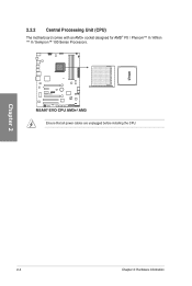
Chapter 2 2-4 Chapter 2: Hardware information 2.2.2 Central Processing Unit (CPU) The motherboard comes with an AM3+ socket designed for AMD® FX / Phenom™ II / Athlon ™ II / Sempron™ 100 Series Processors. Ensure that all power cables are unplugged before installing the CPU.
Chapter 2 2-4 Chapter 2: Hardware information 2.2.2 Central Processing Unit (CPU) The motherboard comes with an AM3+ socket designed for AMD® FX / Phenom™ II / Athlon ™ II / Sempron™ 100 Series Processors. Ensure that all power cables are unplugged before installing the CPU.

User Manual
Page 38
... root problem within a second. 2. This user-friendly design provides an intuitional way to indicate that you should shut down the system and unplug the power cable before removing or plugging in soft‑off mode. This is a reminder that the system is solved. Standby Power LED The motherboard comes with a standby...
... root problem within a second. 2. This user-friendly design provides an intuitional way to indicate that you should shut down the system and unplug the power cable before removing or plugging in soft‑off mode. This is a reminder that the system is solved. Standby Power LED The motherboard comes with a standby...

User Manual
Page 40
.... AMD® SB950 Serial ATA 6.0 Gb/s connectors (7-pin SATA6G_1-6 [gray]) These connectors connect to Serial ATA 6.0 Gb/s hard disk drives via Serial ATA 6.0 Gb/s signal cables.
.... AMD® SB950 Serial ATA 6.0 Gb/s connectors (7-pin SATA6G_1-6 [gray]) These connectors connect to Serial ATA 6.0 Gb/s hard disk drives via Serial ATA 6.0 Gb/s signal cables.

User Manual
Page 41
... any of these connectors, then install the module to the USB connectors. 2. If the USB 3.0 front panel cable is available from your chassis supports front panel USB ports. Never connect a 1394 cable to a slot opening at the back of the system chassis. USB1314) These connectors are for the additional USB 3.0 ports,... to 48 MBps connection speed. Doing so will damage the motherboard! The USB 2.0 module is for USB 2.0 ports. USB 2.0 connectors (10-1 pin USB910, USB1112; ASUS M5A97 EVO 2-23 USB 3.0 connector (20-1 pin USB3_34) This connector is purchased separately.
... any of these connectors, then install the module to the USB connectors. 2. If the USB 3.0 front panel cable is available from your chassis supports front panel USB ports. Never connect a 1394 cable to a slot opening at the back of the system chassis. USB1314) These connectors are for the additional USB 3.0 ports,... to 48 MBps connection speed. Doing so will damage the motherboard! The USB 2.0 module is for USB 2.0 ports. USB 2.0 connectors (10-1 pin USB910, USB1112; ASUS M5A97 EVO 2-23 USB 3.0 connector (20-1 pin USB3_34) This connector is purchased separately.

User Manual
Page 42
Connect the IEEE 1394a module cable to this connector, then install the module to a slot opening at the back of the system chassis. Doing so will damage the motherboard! The S/PDIF ...) This connector is for an additional Sony/Philips Digital Interface (S/PDIF) port(s). Connect the S/PDIF Out module cable to this connector, then install the module to the IEEE 1394a connector. 4. Chapter 2 Never connect a USB cable to a slot opening at the back of the system chassis. IEEE 1394a port connector (10-1 pin IE1394_2...
Connect the IEEE 1394a module cable to this connector, then install the module to a slot opening at the back of the system chassis. Doing so will damage the motherboard! The S/PDIF ...) This connector is for an additional Sony/Philips Digital Interface (S/PDIF) port(s). Connect the S/PDIF Out module cable to this connector, then install the module to the IEEE 1394a connector. 4. Chapter 2 Never connect a USB cable to a slot opening at the back of the system chassis. IEEE 1394a port connector (10-1 pin IE1394_2...

User Manual
Page 43
...serial port bracket (COM1) is for a chassis-mounted front panel audio I /O module cable to [AC97]. Front panel audio connector (10-1 pin AAFP) This connector is set to [HD]; By default, this connector. ASUS M5A97 EVO 2-25 Chapter 2 • We recommend that supports either HD Audio or legacy AC...`97 audio standard. Connect the serial port module cable to the connector, then install the module to avail of the system ...
...serial port bracket (COM1) is for a chassis-mounted front panel audio I /O module cable to [AC97]. Front panel audio connector (10-1 pin AAFP) This connector is set to [HD]; By default, this connector. ASUS M5A97 EVO 2-25 Chapter 2 • We recommend that supports either HD Audio or legacy AC...`97 audio standard. Connect the serial port module cable to the connector, then install the module to avail of the system ...

User Manual
Page 44
..., ensuring that you install two VGA cards, we recommend that the black wire of each cable matches the ground pin of the connector. 8. Chapter 2 Do not forget to connect the fan cables to the motherboard connector labeled CHA_FAN1 or CHA_FAN2 for better thermal environment. 2-26 Chapter 2: ... may damage the motherboard components. CPU, chassis, and power fan connectors (4-pin CPU_FAN; 4-pin CHA_FAN1; 3-pin CHA_FAN2; 3-pin PWR_FAN) Connect the fan cables to the fan connectors on the fan connectors! • The CPU_FAN connector supports the CPU fan of maximum 1A (12 W) fan power. •...
..., ensuring that you install two VGA cards, we recommend that the black wire of each cable matches the ground pin of the connector. 8. Chapter 2 Do not forget to connect the fan cables to the motherboard connector labeled CHA_FAN1 or CHA_FAN2 for better thermal environment. 2-26 Chapter 2: ... may damage the motherboard components. CPU, chassis, and power fan connectors (4-pin CPU_FAN; 4-pin CHA_FAN1; 3-pin CHA_FAN2; 3-pin PWR_FAN) Connect the fan cables to the fan connectors on the fan connectors! • The CPU_FAN connector supports the CPU fan of maximum 1A (12 W) fan power. •...

User Manual
Page 46
Connect the HDD Activity LED cable to hear system beeps and warnings. • ATX power button/soft-off button (2-pin PWRSW) This connector is for the chassis-mounted system warning speaker. ... is ON turns the system OFF. • Reset button (2-pin RESET) This 2-pin connector is for the HDD Activity LED. Connect the chassis power LED cable to the HDD. • System warning speaker (4-pin SPEAKER) This 4-pin connector is for the system power LED. The system power LED lights up or...
Connect the HDD Activity LED cable to hear system beeps and warnings. • ATX power button/soft-off button (2-pin PWRSW) This connector is for the chassis-mounted system warning speaker. ... is ON turns the system OFF. • Reset button (2-pin RESET) This 2-pin connector is for the HDD Activity LED. Connect the chassis power LED cable to the HDD. • System warning speaker (4-pin SPEAKER) This 4-pin connector is for the system power LED. The system power LED lights up or...

User Manual
Page 116
... button Exit button Minimize button Chapter 4 Information button Refer to the software manual in the support DVD or visit the ASUS website at www.asus.com for Windows® Vista™ Set default device button Minimize button Configuration option tabs Exit button Device advanced settings ... Audio Manager. The CODEC also includes the Realtek® proprietary UAJ® (Universal Audio Jack) technology for all audio ports, eliminating cable connection errors and giving users plug and play convenience. If the Realtek audio software is correctly installed, you will find the Realtek HD...
... button Exit button Minimize button Chapter 4 Information button Refer to the software manual in the support DVD or visit the ASUS website at www.asus.com for Windows® Vista™ Set default device button Minimize button Configuration option tabs Exit button Device advanced settings ... Audio Manager. The CODEC also includes the Realtek® proprietary UAJ® (Universal Audio Jack) technology for all audio ports, eliminating cable connection errors and giving users plug and play convenience. If the Realtek audio software is correctly installed, you will find the Realtek HD...

User Manual
Page 118
... function in the BIOS Setup before creating RAID set any of the same model and capacity when creating a disk array. Connect the SATA signal cables. 3. Connect a SATA power cable to Chapter 3 for a RAID configuration: 1. Save your changes, and then exit the BIOS Setup. Go to UEFI Advanced Mode and go to [RAID...
... function in the BIOS Setup before creating RAID set any of the same model and capacity when creating a disk array. Connect the SATA signal cables. 3. Connect a SATA power cable to Chapter 3 for a RAID configuration: 1. Save your changes, and then exit the BIOS Setup. Go to UEFI Advanced Mode and go to [RAID...

User Manual
Page 128
... cards are for multi-graphics card installation. 3. If your motherboard has more than two PCIEX16 slots, refer to the graphics card. Connect a VGA or a DVI cable to Chapter 2 in place. Prepare two CrossFireX-ready graphics cards. 2.
... cards are for multi-graphics card installation. 3. If your motherboard has more than two PCIEX16 slots, refer to the graphics card. Connect a VGA or a DVI cable to Chapter 2 in place. Prepare two CrossFireX-ready graphics cards. 2.


