
User Manual
Page 13
M5A88-V EVO specifications summary Back panel I/O ports Internal...in x 9.6 in -1 Q-connector (retail version only) 1 x I /O ports 4 x USB 2.0/1.1 connectors support additional 8 USB 2.0/1.1 ports 1 x COM connector 1 x IDE connector 5 x SATA 6.0Gb/s connectors 1 x CPU fan connector 1 x Chassis fan connector 1 x Power fan connector 1 x Front panel audio connector 1 x S/PDIF output...AMI BIOS, PnP, DMI2.0, WfM2.0, ACPI2.0a, SM BIOS 2.5, ASUS EZ Flash 2, ASUS CrashFree BIOS 3 WOL by PME, WOR by PME, WOR by Ring, PXE Drivers ASUS Update ASUS utilities Anti-Virus software (OEM version) 2 x Serial ATA 6....
M5A88-V EVO specifications summary Back panel I/O ports Internal...in x 9.6 in -1 Q-connector (retail version only) 1 x I /O ports 4 x USB 2.0/1.1 connectors support additional 8 USB 2.0/1.1 ports 1 x COM connector 1 x IDE connector 5 x SATA 6.0Gb/s connectors 1 x CPU fan connector 1 x Chassis fan connector 1 x Power fan connector 1 x Front panel audio connector 1 x S/PDIF output...AMI BIOS, PnP, DMI2.0, WfM2.0, ACPI2.0a, SM BIOS 2.5, ASUS EZ Flash 2, ASUS CrashFree BIOS 3 WOL by PME, WOR by PME, WOR by Ring, PXE Drivers ASUS Update ASUS utilities Anti-Virus software (OEM version) 2 x Serial ATA 6....
User Manual
Page 83
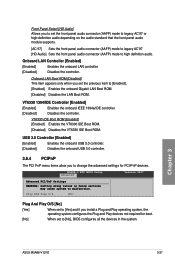
Chapter 3 ASUS M5A88-V EVO 3-27 Onboard LAN Boot ROM [Disabled] This item appears only when you install a Plug and Play operating system, the operating system configures the Plug and Play devices not required for PCI/PnP devices. VT6330 IDE Boot ROM [Enabled] [Enabled] Enables the VT6330 IDE Boot ROM. [Disabled] Disables the VT6330 IDE Boot ROM. Plug...
Chapter 3 ASUS M5A88-V EVO 3-27 Onboard LAN Boot ROM [Disabled] This item appears only when you install a Plug and Play operating system, the operating system configures the Plug and Play devices not required for PCI/PnP devices. VT6330 IDE Boot ROM [Enabled] [Enabled] Enables the VT6330 IDE Boot ROM. [Disabled] Disables the VT6330 IDE Boot ROM. Plug...
User Manual
Page 114
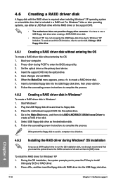
To work around this OS limitation, refer to Windows® XP limitation. Save changes and exit BIOS. 6. Insert a formatted floppy disk into the optical drive. 4. Plug the USB floppy disk drive and insert a floppy disk. 3. Press , and then...screen instructions to create a RAID driver disk. 7. Write-protect the floppy disk to avoid a computer virus infection. 4.6.3 Installing the RAID driver during POST to [IDE] mode. Set the optical drive as the destination disk. 6. Follow the succeeding screen instructions to complete the process. 4.6.2 Creating a RAID driver disk in Windows®...
To work around this OS limitation, refer to Windows® XP limitation. Save changes and exit BIOS. 6. Insert a formatted floppy disk into the optical drive. 4. Plug the USB floppy disk drive and insert a floppy disk. 3. Press , and then...screen instructions to create a RAID driver disk. 7. Write-protect the floppy disk to avoid a computer virus infection. 4.6.3 Installing the RAID driver during POST to [IDE] mode. Set the optical drive as the destination disk. 6. Follow the succeeding screen instructions to complete the process. 4.6.2 Creating a RAID driver disk in Windows®...


