
User Manual
Page 2
...INFORMATIONAL USE ONLY, AND ARE SUBJECT TO CHANGE AT ANY TIME WITHOUT NOTICE, AND SHOULD NOT BE CONSTRUED AS A COMMITMENT BY ASUS. ASUS ASSUMES NO RESPONSIBILITY OR LIABILITY FOR ANY ERRORS OR INACCURACIES THAT MAY APPEAR IN THIS MANUAL, INCLUDING THE PRODUCTS AND SOFTWARE DESCRIBED... product for identification or explanation and to the owners' benefit, without any means, except documentation kept by downloading it from http://support.asus.com/download; E5996 First Edition V1 August 2010 Copyright © 2010 ASUSTeK Computer Inc. Products and corporate names appearing in any...
...INFORMATIONAL USE ONLY, AND ARE SUBJECT TO CHANGE AT ANY TIME WITHOUT NOTICE, AND SHOULD NOT BE CONSTRUED AS A COMMITMENT BY ASUS. ASUS ASSUMES NO RESPONSIBILITY OR LIABILITY FOR ANY ERRORS OR INACCURACIES THAT MAY APPEAR IN THIS MANUAL, INCLUDING THE PRODUCTS AND SOFTWARE DESCRIBED... product for identification or explanation and to the owners' benefit, without any means, except documentation kept by downloading it from http://support.asus.com/download; E5996 First Edition V1 August 2010 Copyright © 2010 ASUSTeK Computer Inc. Products and corporate names appearing in any...

User Manual
Page 4
... 1.11.1 Installing an operating system 1-27 1.11.2 Support DVD information 1-27 Chapter 2: BIOS information 2.1 Managing and updating your BIOS 2-1 2.1.1 ASUS Update 2-1 2.1.2 ASUS EZ Flash 2 2-2 2.1.3 ASUS CrashFree BIOS 3 2-3 2.2 BIOS setup program 2-4 2.2.1 BIOS menu screen 2-5 2.2.3 Navigation keys 2-5 2.2.2 Menu bar 2-5 2.2.4 Menu items 2-6 2.2.5 Submenu items 2-6 2.2.6 ... 2.4.4 Onboard Devices Configuration 2-14 2.4.5 PCIPnP 2-14 2.4.6 USB Configuration 2-14 2.5 Power menu 2-16 2.5.1 Suspend Mode 2-16 2.5.2 ACPI 2.0 Support 2-16 2.5.3 ACPI APIC Support 2-16 iv
... 1.11.1 Installing an operating system 1-27 1.11.2 Support DVD information 1-27 Chapter 2: BIOS information 2.1 Managing and updating your BIOS 2-1 2.1.1 ASUS Update 2-1 2.1.2 ASUS EZ Flash 2 2-2 2.1.3 ASUS CrashFree BIOS 3 2-3 2.2 BIOS setup program 2-4 2.2.1 BIOS menu screen 2-5 2.2.3 Navigation keys 2-5 2.2.2 Menu bar 2-5 2.2.4 Menu items 2-6 2.2.5 Submenu items 2-6 2.2.6 ... 2.4.4 Onboard Devices Configuration 2-14 2.4.5 PCIPnP 2-14 2.4.6 USB Configuration 2-14 2.5 Power menu 2-16 2.5.1 Suspend Mode 2-16 2.5.2 ACPI 2.0 Support 2-16 2.5.3 ACPI APIC Support 2-16 iv

User Manual
Page 7
... is organized This guide contains the following parts: • Chapter 1: Product introduction This chapter describes the features of the motherboard and the new technology it supports. • Chapter 2: BIOS information This chapter tells how to fix it , carefully read all the manuals that all power cables from the existing system before...
... is organized This guide contains the following parts: • Chapter 1: Product introduction This chapter describes the features of the motherboard and the new technology it supports. • Chapter 2: BIOS information This chapter tells how to fix it , carefully read all the manuals that all power cables from the existing system before...

User Manual
Page 9
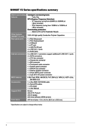
...HD audio module in the front panel to support an 8-channel audio output. 10 x USB 2.0/1.1 ports (6 ports at the mid-board, 4 ports at the mid-board - With ASUS design, this motherboard can support up to DDR3 1066MHz. M4N68T V2 Series specifications summary CPU Chipset System bus Memory ...Expansion slots Storage LAN Audio USB ASUS unique features AMD® Socket AM3 for AMD® Phenom™ II...
...HD audio module in the front panel to support an 8-channel audio output. 10 x USB 2.0/1.1 ports (6 ports at the mid-board, 4 ports at the mid-board - With ASUS design, this motherboard can support up to DDR3 1066MHz. M4N68T V2 Series specifications summary CPU Chipset System bus Memory ...Expansion slots Storage LAN Audio USB ASUS unique features AMD® Socket AM3 for AMD® Phenom™ II...
User Manual
Page 10
M4N68T V2 Series specifications summary ASUS overclocking features Other features (M4N68T V2 only) Rear panel ports Internal connectors BIOS features Accessories Support DVD Form factor Intelligent overclocking tools: - HT frequency tuning from 100MHz to 150MHz at 1MHz increment - Turbo Key SFS (Stepless Frequency Selection): - ASUS...connector 8 Mb Flash ROM, AMI BIOS, PnP, DMI v2.0, WfM 2.0, ACPI v2.0a, SM BIOS v2.5 1 x Ultra DMA 133/100/66 cable 2 x Serial ATA cables 1 x I/O shield 1 x User Manual Drivers ASUS PC Probe II ASUS Update Anti-virus software (OEM version) ATX form factor: ...
M4N68T V2 Series specifications summary ASUS overclocking features Other features (M4N68T V2 only) Rear panel ports Internal connectors BIOS features Accessories Support DVD Form factor Intelligent overclocking tools: - HT frequency tuning from 100MHz to 150MHz at 1MHz increment - Turbo Key SFS (Stepless Frequency Selection): - ASUS...connector 8 Mb Flash ROM, AMI BIOS, PnP, DMI v2.0, WfM 2.0, ACPI v2.0a, SM BIOS v2.5 1 x Ultra DMA 133/100/66 cable 2 x Serial ATA cables 1 x I/O shield 1 x User Manual Drivers ASUS PC Probe II ASUS Update Anti-virus software (OEM version) ATX form factor: ...

User Manual
Page 11
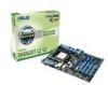
... HyperTransport™ 1.0based system bus. Before you for the following items. Motherboard Cables Accessories Application DVD Documentation ASUS M4N68T V2 Series motherboard 2 x Serial ATA cables 1 x Ultra DMA 133/100/66 cable 1 x I/O shield ASUS motherboard Support DVD User Manual • M4N68T V2 Series motherboards include M4N68T V2 and M4N68T LE V2 two models. Chapter 1 Product introduction 1.1 Welcome! It features dual-channel DDR3 memory...
... HyperTransport™ 1.0based system bus. Before you for the following items. Motherboard Cables Accessories Application DVD Documentation ASUS M4N68T V2 Series motherboard 2 x Serial ATA cables 1 x Ultra DMA 133/100/66 cable 1 x I/O shield ASUS motherboard Support DVD User Manual • M4N68T V2 Series motherboards include M4N68T V2 and M4N68T LE V2 two models. Chapter 1 Product introduction 1.1 Welcome! It features dual-channel DDR3 memory...

User Manual
Page 12
... for durability, improved lifespan, and enhanced thermal capacity. 1-2 Chapter 1: Product introduction Dual-Channel DDR3 1800 (O.C.) support This motherboard supports DDR3 memory that simultaneously sends different audio streams to meet the higher bandwidth requirements of the latest operating system,...operating systems. Serial ATA 3Gb/s technology and RAID support This motherboard supports hard drives based on the headphone while playing multichannel network games. 100% All High-quality Conductive Polymer Capacitors (M4N68T V2 only) This motherboard uses all high-quality conductive ...
... for durability, improved lifespan, and enhanced thermal capacity. 1-2 Chapter 1: Product introduction Dual-Channel DDR3 1800 (O.C.) support This motherboard supports DDR3 memory that simultaneously sends different audio streams to meet the higher bandwidth requirements of the latest operating system,...operating systems. Serial ATA 3Gb/s technology and RAID support This motherboard supports hard drives based on the headphone while playing multichannel network games. 100% All High-quality Conductive Polymer Capacitors (M4N68T V2 only) This motherboard uses all high-quality conductive ...

User Manual
Page 13
... restore a corrupted BIOS file using the bundled support DVD or a USB flash disk that allows you to 100 meters at 1 meter accuracy. ASUS M4N68T V2 Series 1-3 1.3.2 Innovative ASUS features Core Unlocker ASUS Core Unlocker simplifies the activation of a latent AMD® CPU- ASUS MyLogo2™ Turn your system. ASUS Turbo Key ASUS Turbo Key allows you to activate the...
... restore a corrupted BIOS file using the bundled support DVD or a USB flash disk that allows you to 100 meters at 1 meter accuracy. ASUS M4N68T V2 Series 1-3 1.3.2 Innovative ASUS features Core Unlocker ASUS Core Unlocker simplifies the activation of a latent AMD® CPU- ASUS MyLogo2™ Turn your system. ASUS Turbo Key ASUS Turbo Key allows you to activate the...

User Manual
Page 21
... N/A Heat-Sink Package N/A Heat-Sink Package N/A Heat-Sink Package CL N/A 8-8-8-24 9-9-9-27 8-8-8-24 DIMM support A* B* C* • • • • • • • ASUS M4N68T V2 Series 1-11 Install a maximum of 3GB system memory if you do any of the following: - M4N68T V2 series Motherboards Qualified Vendors Lists (QVL) DDR3-1800(O.C.) MHz capability Vendor Part No. The...
... N/A Heat-Sink Package N/A Heat-Sink Package N/A Heat-Sink Package CL N/A 8-8-8-24 9-9-9-27 8-8-8-24 DIMM support A* B* C* • • • • • • • ASUS M4N68T V2 Series 1-11 Install a maximum of 3GB system memory if you do any of the following: - M4N68T V2 series Motherboards Qualified Vendors Lists (QVL) DDR3-1800(O.C.) MHz capability Vendor Part No. The...

User Manual
Page 22
...Heat-Sink Package Heat-Sink Package 7-7-7-20 9-9-9-24 8-8-8-24 9-9-9-28 8-8-8-24 8-8-8-24 8-8-8-24 9-9-9-24 8-8-8-21 9-9-9-24 N/A N/A 8-8-8-24 9-9-9-27 8-8-8-24 DIMM support A* B* C* • • • • • • • • • • • • &#...Sink Package Heat-Sink Package Heat-Sink Package Heat-Sink Package CL N/A N/A 9 9 N/A N/A 9 N/A 6-6-6-20 9 6-6-6-20 9 N/A N/A 7-7-7-18 9-9-9-24 N/A DIMM support A* B* C* • • • • • • • • • • • • • • ...
...Heat-Sink Package Heat-Sink Package 7-7-7-20 9-9-9-24 8-8-8-24 9-9-9-28 8-8-8-24 8-8-8-24 8-8-8-24 9-9-9-24 8-8-8-21 9-9-9-24 N/A N/A 8-8-8-24 9-9-9-27 8-8-8-24 DIMM support A* B* C* • • • • • • • • • • • • &#...Sink Package Heat-Sink Package Heat-Sink Package Heat-Sink Package CL N/A N/A 9 9 N/A N/A 9 N/A 6-6-6-20 9 6-6-6-20 9 N/A N/A 7-7-7-18 9-9-9-24 N/A DIMM support A* B* C* • • • • • • • • • • • • • • ...

User Manual
Page 23
... K4B1G0846D Heat-Sink Package Heat-Sink Package PM64M8D38U-15 Heat-Sink Package Heat-Sink Package N/A N/A 7-7-7-18 9-9-9-24 9 7-7-7-24 9 9 9 N/A N/A 9 9 7-7-7-20 N/A N/A N/A N/A N/A N/A N/A N/A N/A N/A N/A 8-8-8-24 N/A N/A N/A N/A N/A 9 N/A 7-7-7-20 8-8-8-24 DIMM support A* B* C • •• • •• • •• • •• ASUS M4N68T V2 Series 1-13 Size SS/ Chip DS Brand Chip NO. DDR3-1333MHz capability Vendor Part No.
... K4B1G0846D Heat-Sink Package Heat-Sink Package PM64M8D38U-15 Heat-Sink Package Heat-Sink Package N/A N/A 7-7-7-18 9-9-9-24 9 7-7-7-24 9 9 9 N/A N/A 9 9 7-7-7-20 N/A N/A N/A N/A N/A N/A N/A N/A N/A N/A N/A 8-8-8-24 N/A N/A N/A N/A N/A 9 N/A 7-7-7-20 8-8-8-24 DIMM support A* B* C • •• • •• • •• • •• ASUS M4N68T V2 Series 1-13 Size SS/ Chip DS Brand Chip NO. DDR3-1333MHz capability Vendor Part No.

User Manual
Page 24
DDR3-1066MHz capability Vendor Part No. DIMM support CL A* B* C* Elpida EBJ51UD8BAFA-AC-E 512MB SS elpida J5308BASE-AC-E N/A • • • Elpida...8226; • SS: Single-sided / DS: Double-sided DIMM support: • A*: Supports one module inserted into any slot as Single-channel memory configuration. • B*: Supports one pair of modules inserted into either the blue slots or the ...black slots as one pair of Dual-channel memory configuration. • C*: Supports two pairs of modules inserted into both the blue and the black slots as two pairs of...
DDR3-1066MHz capability Vendor Part No. DIMM support CL A* B* C* Elpida EBJ51UD8BAFA-AC-E 512MB SS elpida J5308BASE-AC-E N/A • • • Elpida...8226; • SS: Single-sided / DS: Double-sided DIMM support: • A*: Supports one module inserted into any slot as Single-channel memory configuration. • B*: Supports one pair of modules inserted into either the blue slots or the ...black slots as one pair of Dual-channel memory configuration. • C*: Supports two pairs of modules inserted into both the blue and the black slots as two pairs of...

User Manual
Page 25
DIMM notch ASUS M4N68T V2 Series 1-15 1.7.3 Installing a DIMM Unplug the power supply before adding or removing DIMMs or other system components. Press the retaining clips outward to avoid damaging ... to both the motherboard and the components. 1. Remove the DIMM from the socket. Failure to do so can cause severe damage to unlock the DIMM. 2 Support the DIMM lightly with extra force. 1 2. The DIMM might get damaged when it fits in place 3 and the DIMM is keyed with a notch so that...
DIMM notch ASUS M4N68T V2 Series 1-15 1.7.3 Installing a DIMM Unplug the power supply before adding or removing DIMMs or other system components. Press the retaining clips outward to avoid damaging ... to both the motherboard and the components. 1. Remove the DIMM from the socket. Failure to do so can cause severe damage to unlock the DIMM. 2 Support the DIMM lightly with extra force. 1 2. The DIMM might get damaged when it fits in place 3 and the DIMM is keyed with a notch so that...

User Manual
Page 26
... cards. Turn on BIOS setup. 2. Remove the system unit cover (if your motherboard is completely seated on shared slots, ensure that the drivers support "Share IRQ" or that came with the slot and press firmly until the card is already installed in a chassis). 3. When using PCI cards... cards that you intend to the card. 3. Install the software drivers for the card. 2. Remove the bracket opposite the slot that they support. 1.8 Expansion slots In the future, you may cause you physical injury and damage motherboard components. 1.8.1 Installing an expansion card To install an expansion...
... cards. Turn on BIOS setup. 2. Remove the system unit cover (if your motherboard is completely seated on shared slots, ensure that the drivers support "Share IRQ" or that came with the slot and press firmly until the card is already installed in a chassis). 3. When using PCI cards... cards that you intend to the card. 3. Install the software drivers for the card. 2. Remove the bracket opposite the slot that they support. 1.8 Expansion slots In the future, you may cause you physical injury and damage motherboard components. 1.8.1 Installing an expansion card To install an expansion...

User Manual
Page 29
... 100Mbps connection 1Gbps connection ACT/LINK SPEED LED LED LAN port 4. This port connects to a Local Area Network (LAN) through a network hub. ASUS M4N68T V2 Series 1-19 This 25-pin port connects a parallel printer, a scanner, or other audio sources. 5. Refer to the tape, CD, DVD player...PS/2 mouse. 2. This port is for the function of this port becomes Front Speaker Out. 6. Line Out port (lime). This port connects to support 8-channel audio output. Audio 2, 4, 6, or 8-channel configuration Port Light Blue (Rear panel) Lime (Rear panel) Pink (Rear panel) Lime (Front...
... 100Mbps connection 1Gbps connection ACT/LINK SPEED LED LED LAN port 4. This port connects to a Local Area Network (LAN) through a network hub. ASUS M4N68T V2 Series 1-19 This 25-pin port connects a parallel printer, a scanner, or other audio sources. 5. Refer to the tape, CD, DVD player...PS/2 mouse. 2. This port is for the function of this port becomes Front Speaker Out. 6. Line Out port (lime). This port connects to support 8-channel audio output. Audio 2, 4, 6, or 8-channel configuration Port Light Blue (Rear panel) Lime (Rear panel) Pink (Rear panel) Lime (Front...

User Manual
Page 30
...1 and 2. These two 4-pin Universal Serial Bus (USB) ports connect to USB 2.0 devices. 9. GND PRESENCE# SENSE1_RETUR SENSE2_RETUR AGND NC NC NC M4N68T V2 Series AAFP PIN 1 PIN 1 MIC2 MICPWR Line out_R NC Line out_L PORT1 L PORT1 R PORT2 R SENSE_SEND PORT2 L HD-audio-compliant Legacy AC'97... pin definition compliant definition M4N68T V2 Series Front panel audio connector • We recommend that supports either High Definition Audio or AC`97 audio standard. USB 2.0 ports 3 and 4. Connect one end of...
...1 and 2. These two 4-pin Universal Serial Bus (USB) ports connect to USB 2.0 devices. 9. GND PRESENCE# SENSE1_RETUR SENSE2_RETUR AGND NC NC NC M4N68T V2 Series AAFP PIN 1 PIN 1 MIC2 MICPWR Line out_R NC Line out_L PORT1 L PORT1 R PORT2 R SENSE_SEND PORT2 L HD-audio-compliant Legacy AC'97... pin definition compliant definition M4N68T V2 Series Front panel audio connector • We recommend that supports either High Definition Audio or AC`97 audio standard. USB 2.0 ports 3 and 4. Connect one end of...

User Manual
Page 31
... +5 Volts GND +5 Volts GND +3 Volts +3 Volts PIN 1 M4N68T V2 Series ATX power connectors GND +5 Volts +5 Volts +5 Volts -5 Volts GND GND GND PSON# GND -12 Volts +3 Volts • We recommend that the 20-pin power plug can provide at http://support.asus. The system may become unstable or may not boot up..., the system will not boot up if the power is inadequate. • DO NOT forget to use a PSU with a minimum of 300W. ASUS M4N68T V2 Series 1-21 The system may become unstable or may not boot up if the power is inadequate. • If you use an ATX 12V Specification...
... +5 Volts GND +5 Volts GND +3 Volts +3 Volts PIN 1 M4N68T V2 Series ATX power connectors GND +5 Volts +5 Volts +5 Volts -5 Volts GND GND GND PSON# GND -12 Volts +3 Volts • We recommend that the 20-pin power plug can provide at http://support.asus. The system may become unstable or may not boot up..., the system will not boot up if the power is inadequate. • DO NOT forget to use a PSU with a minimum of 300W. ASUS M4N68T V2 Series 1-21 The system may become unstable or may not boot up if the power is inadequate. • If you use an ATX 12V Specification...

User Manual
Page 33
... RSATA_TXP1 GND GND RSATA_RXN2 RSATA_RXP2 GND RSATA_TXN2 RSATA_TXP2 GND GND RSATA_RXN3 RSATA_RXP3 GND RSATA_TXN3 RSATA_TXP3 GND GND RSATA_RXN4 RSATA_RXP4 GND RSATA_TXN4 RSATA_TXP4 GND M4N68T V2 Series SATA connectors • Install the Windows® XP Service Pack 2 or later versions before using Serial ATA. • ... the nVidia RAID Function item in the BIOS to the RAID/AHCI Supplementary Guide included in the folder named Manual in the support DVD. ASUS M4N68T V2 Series 1-23 The data transfer rate of the Serial ATA 3Gb/s is backward compatible with 133MB/s (Ultra DMA133). Serial ATA...
... RSATA_TXP1 GND GND RSATA_RXN2 RSATA_RXP2 GND RSATA_TXN2 RSATA_TXP2 GND GND RSATA_RXN3 RSATA_RXP3 GND RSATA_TXN3 RSATA_TXP3 GND GND RSATA_RXN4 RSATA_RXP4 GND RSATA_TXN4 RSATA_TXP4 GND M4N68T V2 Series SATA connectors • Install the Windows® XP Service Pack 2 or later versions before using Serial ATA. • ... the nVidia RAID Function item in the BIOS to the RAID/AHCI Supplementary Guide included in the folder named Manual in the support DVD. ASUS M4N68T V2 Series 1-23 The data transfer rate of the Serial ATA 3Gb/s is backward compatible with 133MB/s (Ultra DMA133). Serial ATA...

User Manual
Page 34
...LED lights up when you to this connector. System panel connector (10-1 pin F_PANEL) This connector supports several chassis-mounted functions. PWR LED PWR BTN PLED+ PLEDPWR GND M4N68T V2 Series F_PANEL PIN 1 IDE_LED+ IDE_LED- Connect the HDD Activity LED cable to hear system beeps and ...warnings. +5V GND GND Speaker Out SPEAKER M4N68T V2 Series PIN 1 M4N68T V2 Series Internal speaker connector 1-24 Chapter 1: Product introduction The speaker allows you turn on the system power, and blinks when ...
...LED lights up when you to this connector. System panel connector (10-1 pin F_PANEL) This connector supports several chassis-mounted functions. PWR LED PWR BTN PLED+ PLEDPWR GND M4N68T V2 Series F_PANEL PIN 1 IDE_LED+ IDE_LED- Connect the HDD Activity LED cable to hear system beeps and ...warnings. +5V GND GND Speaker Out SPEAKER M4N68T V2 Series PIN 1 M4N68T V2 Series Internal speaker connector 1-24 Chapter 1: Product introduction The speaker allows you turn on the system power, and blinks when ...

User Manual
Page 35
ASUS M4N68T V2 Series 1-25 USB+5V USB_P6USB_P6+ GND NC USB+5V USB_P8USB_P8+ GND NC USB+5V USB_P10USB_P10+ GND NC M4N68T V2 Series USB56 USB78 USB910 PIN 1 PIN 1 PIN 1 USB+5V USB_P5USB_P5+ GND USB+5V USB_P7USB_P7+ GND USB+5V USB_P9USB_P9+ GND M4N68T V2 Series USB2.0 connectors Never ... USB910) These connectors are for an additional Sony/Philips Digital Interface (S/PDIF) port. +5V SPDIFOUT GND M4N68T V2 Series SPDIF_OUT M4N68T V2 Series Digital audio connector Ensure that supports up to a slot opening at the back of Sound playback is for USB 2.0 ports. Digital audio ...
ASUS M4N68T V2 Series 1-25 USB+5V USB_P6USB_P6+ GND NC USB+5V USB_P8USB_P8+ GND NC USB+5V USB_P10USB_P10+ GND NC M4N68T V2 Series USB56 USB78 USB910 PIN 1 PIN 1 PIN 1 USB+5V USB_P5USB_P5+ GND USB+5V USB_P7USB_P7+ GND USB+5V USB_P9USB_P9+ GND M4N68T V2 Series USB2.0 connectors Never ... USB910) These connectors are for an additional Sony/Philips Digital Interface (S/PDIF) port. +5V SPDIFOUT GND M4N68T V2 Series SPDIF_OUT M4N68T V2 Series Digital audio connector Ensure that supports up to a slot opening at the back of Sound playback is for USB 2.0 ports. Digital audio ...


