User Manual
Page 4
Contents 2.5.6 PCI Express 2.0 x16 slot (blue 2-23 2.5.7 Universal PCI Express x16 slot (black 2-23 2.6 Jumper 2-25 2.7 Connectors 2-26 2.7.1 Rear panel connectors 2-26 2.7.2 Internal connectors 2-29 Chapter 3: Powering up 3.1 Starting...OS shut down function 3-2 3.2.2 Using the dual function power switch 3-2 Chapter 4: BIOS setup 4.1 Managing and updating your BIOS 4-1 4.1.1 ASUS Update utility 4-1 4.1.2 Creating a bootable floppy disk 4-4 4.1.3 ASUS EZ Flash 2 utility 4-5 4.1.4 Updating the BIOS 4-6 4.1.5 Saving the current BIOS file 4-8 4.2 BIOS setup program 4-9 4.2.1 BIOS menu...
Contents 2.5.6 PCI Express 2.0 x16 slot (blue 2-23 2.5.7 Universal PCI Express x16 slot (black 2-23 2.6 Jumper 2-25 2.7 Connectors 2-26 2.7.1 Rear panel connectors 2-26 2.7.2 Internal connectors 2-29 Chapter 3: Powering up 3.1 Starting...OS shut down function 3-2 3.2.2 Using the dual function power switch 3-2 Chapter 4: BIOS setup 4.1 Managing and updating your BIOS 4-1 4.1.1 ASUS Update utility 4-1 4.1.2 Creating a bootable floppy disk 4-4 4.1.3 ASUS EZ Flash 2 utility 4-5 4.1.4 Updating the BIOS 4-6 4.1.5 Saving the current BIOS file 4-8 4.2 BIOS setup program 4-9 4.2.1 BIOS menu...
User Manual
Page 9
It includes description of the switches, jumpers, and connectors on ASUS hardware and software products. ix Where to find more information Refer to the ASUS contact information. 2. Detailed descriptions of the BIOS parameters are not part of shutting down the system. &#...™ support This chapter describes the nVIDIA Hybrid SLI™ feature and shows the graphics card installation procedures. ASUS websites The ASUS website provides updated information on the motherboard. • Chapter 3: Powering up This chapter describes the power up sequence and ways of the standard package....
It includes description of the switches, jumpers, and connectors on ASUS hardware and software products. ix Where to find more information Refer to the ASUS contact information. 2. Detailed descriptions of the BIOS parameters are not part of shutting down the system. &#...™ support This chapter describes the nVIDIA Hybrid SLI™ feature and shows the graphics card installation procedures. ASUS websites The ASUS website provides updated information on the motherboard. • Chapter 3: Powering up This chapter describes the power up sequence and ways of the standard package....
User Manual
Page 23
It includes description of the jumpers and connectors on the motherboard. Chapter 2: 2 Hardware information This chapter lists the hardware setup procedures that you have to perform when installing system components.
It includes description of the jumpers and connectors on the motherboard. Chapter 2: 2 Hardware information This chapter lists the hardware setup procedures that you have to perform when installing system components.
User Manual
Page 24
Chapter summary 2 2.1 Before you proceed 2-1 2.2 Motherboard overview 2-2 2.3 Central Processing Unit (CPU 2-6 2.4 System memory 2-11 2.5 Expansion slots 2-21 2.6 Jumper 2-25 2.7 Connectors 2-26 ASUS M3N72-D
Chapter summary 2 2.1 Before you proceed 2-1 2.2 Motherboard overview 2-2 2.3 Central Processing Unit (CPU 2-6 2.4 System memory 2-11 2.5 Expansion slots 2-21 2.6 Jumper 2-25 2.7 Connectors 2-26 ASUS M3N72-D
User Manual
Page 49
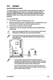
...cord before reboot the system. You must turn ON the computer. 4. ASUS M3N72-D 2-25 The onboard button cell battery powers the RAM data in CMOS. To erase the RTC RAM 1. Keep the cap on CLRTC jumper default position. For system failure due to clear the Real Time Clock (...overclocking. Except when clearing the RTC RAM, never remove the cap on pins 2-3 for about 5~10 seconds, then move the jumper again to pins 1-2. 3. function. Move the jumper cap from pins 1-2 (default) to re-enter data. Removing the cap will cause system boot failure! After the CMOS ...
...cord before reboot the system. You must turn ON the computer. 4. ASUS M3N72-D 2-25 The onboard button cell battery powers the RAM data in CMOS. To erase the RTC RAM 1. Keep the cap on CLRTC jumper default position. For system failure due to clear the Real Time Clock (...overclocking. Except when clearing the RTC RAM, never remove the cap on pins 2-3 for about 5~10 seconds, then move the jumper again to pins 1-2. 3. function. Move the jumper cap from pins 1-2 (default) to re-enter data. Removing the cap will cause system boot failure! After the CMOS ...

User Manual
Page 54
If any device jumper is for Ultra DMA 133/100/66/33 IDE devices. There are three connectors on the IDE connector is removed... PRI_IDE) The onboard IDE connector is set as "Cable-Select," make sure all other device jumpers have the same setting. 2-30 Chapter 2: Hardware information Single device Two devices Drive jumper setting Cable-Select or Master Cable-Select Master Slave Mode of the following modes to match the... on each Ultra DMA 133/100/66/33 signal cable: blue, black, and gray. Connect the blue connector to the motherboard's IDE connector, then select one of device(s) -
If any device jumper is for Ultra DMA 133/100/66/33 IDE devices. There are three connectors on the IDE connector is removed... PRI_IDE) The onboard IDE connector is set as "Cable-Select," make sure all other device jumpers have the same setting. 2-30 Chapter 2: Hardware information Single device Two devices Drive jumper setting Cable-Select or Master Cable-Select Master Slave Mode of the following modes to match the... on each Ultra DMA 133/100/66/33 signal cable: blue, black, and gray. Connect the blue connector to the motherboard's IDE connector, then select one of device(s) -

User Manual
Page 58
...fan connectors on the fan connectors! • Only the CPU_FAN and CHA_FAN 1 connectors support the ASUS Q-FAN 2 feature. • If you plug the rear chassis fan cable to the motherboard connector labeled CHA_FAN1 for better thermal environment. 2-34 Chapter 2: Hardware information Connect the fan cables ...PWR_FAN) The fan connectors support cooling fans of 350 mA~2000 mA (24 W max.) or a total of the connector. Do not place jumper caps on the motherboard, making sure that you install two graphics cards, we recommend that the black wire of each cable matches the ground pin of 1 A~7 ...
...fan connectors on the fan connectors! • Only the CPU_FAN and CHA_FAN 1 connectors support the ASUS Q-FAN 2 feature. • If you plug the rear chassis fan cable to the motherboard connector labeled CHA_FAN1 for better thermal environment. 2-34 Chapter 2: Hardware information Connect the fan cables ...PWR_FAN) The fan connectors support cooling fans of 350 mA~2000 mA (24 W max.) or a total of the connector. Do not place jumper caps on the motherboard, making sure that you install two graphics cards, we recommend that the black wire of each cable matches the ground pin of 1 A~7 ...

User Manual
Page 59
... connector when a chassis component is removed or replaced. The chassis intrusion sensor or switch sends a high-level signal to use the chassis intrusion detection feature. ASUS M3N72-D 2-35 The signal is for a chassis-mounted intrusion detection sensor or switch. 7. Chassis intrusion connector (4-1 pin CHASSIS) This connector is then generated as a chassis intrusion...
... connector when a chassis component is removed or replaced. The chassis intrusion sensor or switch sends a high-level signal to use the chassis intrusion detection feature. ASUS M3N72-D 2-35 The signal is for a chassis-mounted intrusion detection sensor or switch. 7. Chassis intrusion connector (4-1 pin CHASSIS) This connector is then generated as a chassis intrusion...
User Manual
Page 69
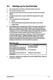
...it has a "power standby" feature, the monitor LED may have failed a power-on test. System power 6. Be sure that is equipped with ATX power supplies, the system LED lights up . Turn on the devices in Chapter 4. After applying power, the system power LED on the system front...enter the BIOS Setup. Check the jumper settings and connections or call your monitor complies with the last device on the chain) c. 3.1 Starting up or switch between orange and green after the system LED turns on. If your retailer for the first time 1. ASUS M3N72-D 3-1 Monitor b. After making all...
...it has a "power standby" feature, the monitor LED may have failed a power-on test. System power 6. Be sure that is equipped with ATX power supplies, the system LED lights up . Turn on the devices in Chapter 4. After applying power, the system power LED on the system front...enter the BIOS Setup. Check the jumper settings and connections or call your monitor complies with the last device on the chain) c. 3.1 Starting up or switch between orange and green after the system LED turns on. If your retailer for the first time 1. ASUS M3N72-D 3-1 Monitor b. After making all...

User Manual
Page 106
...] [System] 4-34 Chapter 4: BIOS setup Press any key to require the password before entering the BIOS Setup. Select [System] to continue. Select [Setup] to section 2.6 Jumper for instructions. 2. The User password is changed to boot the system preventing unauthorized use. If you need to erase the CMOS RAM, refer to require...
...] [System] 4-34 Chapter 4: BIOS setup Press any key to require the password before entering the BIOS Setup. Select [System] to continue. Select [Setup] to section 2.6 Jumper for instructions. 2. The User password is changed to boot the system preventing unauthorized use. If you need to erase the CMOS RAM, refer to require...

