
User Manual
Page 1
Motherboard
Motherboard

User Manual
Page 1
M2N68 PLUS Motherboard
M2N68 PLUS Motherboard

User Manual
Page 3
Contents Notices...vi Safety information vii About this guide vii M2N68 PLUS specifications summary ix Chapter 1: Product introduction 1.1 Welcome 1-1 1.2 Package contents 1-1 1.3 Special features 1-1 1.3.1 Product highlights 1-1 1.3.2 Innovative ASUS features 1-3 1.4 Before you proceed 1-4 1.5 Motherboard overview 1-5 1.5.1 Placement direction 1-5 1.5.2 Screw holes 1-5 1.5.3 Motherboard layout 1-6 1.5.4 Layout contents 1-7 1.6 Central Processing Unit (CPU 1-7 1.6.1 Installing the CPU 1-7 1.6.2 Installing the heatsink and fan 1-9 1.7 System memory 1-10...
Contents Notices...vi Safety information vii About this guide vii M2N68 PLUS specifications summary ix Chapter 1: Product introduction 1.1 Welcome 1-1 1.2 Package contents 1-1 1.3 Special features 1-1 1.3.1 Product highlights 1-1 1.3.2 Innovative ASUS features 1-3 1.4 Before you proceed 1-4 1.5 Motherboard overview 1-5 1.5.1 Placement direction 1-5 1.5.2 Screw holes 1-5 1.5.3 Motherboard layout 1-6 1.5.4 Layout contents 1-7 1.6 Central Processing Unit (CPU 1-7 1.6.1 Installing the CPU 1-7 1.6.2 Installing the heatsink and fan 1-9 1.7 System memory 1-10...
User Manual
Page 6
... help. Canadian Department of Communications Statement This digital apparatus does not exceed the Class B limits for disposal of the FCC Rules. DO NOT throw the motherboard in municipal waste. If this equipment does cause harmful interference to radio or television reception, which the receiver is required to radio communications. This class...
... help. Canadian Department of Communications Statement This digital apparatus does not exceed the Class B limits for disposal of the FCC Rules. DO NOT throw the motherboard in municipal waste. If this equipment does cause harmful interference to radio or television reception, which the receiver is required to radio communications. This class...
User Manual
Page 7
.... • If the power supply is set to the correct voltage in any damage, contact your retailer. Detailed descriptions of the motherboard and the new technology it supports. • Chapter 2: BIOS information This chapter tells how to change system settings through the BIOS Setup...vii How this guide This user guide contains the information you add a device. • Before connecting or removing signal cables from the motherboard, ensure that all power cables are unplugged. • Seek professional assistance before using the product, ensure that all cables are correctly connected...
.... • If the power supply is set to the correct voltage in any damage, contact your retailer. Detailed descriptions of the motherboard and the new technology it supports. • Chapter 2: BIOS information This chapter tells how to change system settings through the BIOS Setup...vii How this guide This user guide contains the information you add a device. • Before connecting or removing signal cables from the motherboard, ensure that all power cables are unplugged. • Seek professional assistance before using the product, ensure that all cables are correctly connected...
User Manual
Page 11
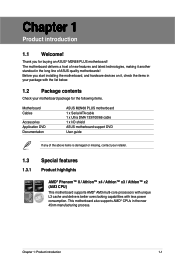
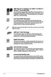
... less power consumption. Before you for the following items. Motherboard Cables Accessories Application DVD Documentation ASUS M2N68 PLUS motherboard 1 x Serial ATA cable 1 x Ultra DMA 133/100/66 cable 1 x I/O shield ASUS motherboard support DVD User guide If any of ASUS quality motherboards! Chapter 1: Product introduction 1-1 Chapter 1 Product introduction 1.1 Welcome! This motherboard also supports AMD® CPUs in the long line of...
... less power consumption. Before you for the following items. Motherboard Cables Accessories Application DVD Documentation ASUS M2N68 PLUS motherboard 1 x Serial ATA cable 1 x Ultra DMA 133/100/66 cable 1 x I/O shield ASUS motherboard support DVD User guide If any of ASUS quality motherboards! Chapter 1: Product introduction 1-1 Chapter 1 Product introduction 1.1 Welcome! This motherboard also supports AMD® CPUs in the long line of...
User Manual
Page 12
... is enhanced with an ACPI management function to www.asus.com for advanced operating systems. Serial ATA 3Gb/s technology This motherboard supports hard drives based on the Serial ATA (SATA) 3Gb/s storage specifications. ALC662 also supports the Windows® Vista Premium OS. 1-2 ASUS M2N68 PLUS Gigabit LAN solution The onboard LAN controller is supported by...
... is enhanced with an ACPI management function to www.asus.com for advanced operating systems. Serial ATA 3Gb/s technology This motherboard supports hard drives based on the Serial ATA (SATA) 3Gb/s storage specifications. ALC662 also supports the Windows® Vista Premium OS. 1-2 ASUS M2N68 PLUS Gigabit LAN solution The onboard LAN controller is supported by...
User Manual
Page 13
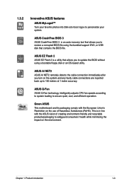
... allows you to restore a corrupted BIOS file using a bootable floppy disk or an OS-based utility. Green ASUS This motherboard and its packaging comply with the ASUS vision of creating environment-friendly and recyclable products/packaging to 100 meters at 1 meter accuracy. This is in ...line with the European Union's Restriction on the environment. ASUS AI NET2 ASUS AI NET2 remotely detects the cable connection ...
... allows you to restore a corrupted BIOS file using a bootable floppy disk or an OS-based utility. Green ASUS This motherboard and its packaging comply with the ASUS vision of creating environment-friendly and recyclable products/packaging to 100 meters at 1 meter accuracy. This is in ...line with the European Union's Restriction on the environment. ASUS AI NET2 ASUS AI NET2 remotely detects the cable connection ...
User Manual
Page 14
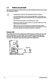
... to avoid damaging them . • Whenever you uninstall any motherboard settings. • Unplug the power cord from the power supply. M2N68 PLUS SB_PWR ON OFF Standby Power Powered Off M2N68 PLUS Onboard LED 1-4 ASUS M2N68 PLUS 1.4 Before you proceed Take note of the onboard LED. Failure... to do so may cause severe damage to the motherboard, peripherals, or components. This is ...
... to avoid damaging them . • Whenever you uninstall any motherboard settings. • Unplug the power cord from the power supply. M2N68 PLUS SB_PWR ON OFF Standby Power Powered Off M2N68 PLUS Onboard LED 1-4 ASUS M2N68 PLUS 1.4 Before you proceed Take note of the onboard LED. Failure... to do so may cause severe damage to the motherboard, peripherals, or components. This is ...
User Manual
Page 15
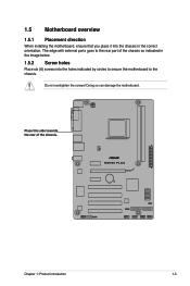
Chapter 1: Product introduction 1-5 1.5 Motherboard overview 1.5.1 Placement direction When installing the motherboard, ensure that you place it into the holes indicated by circles to secure the motherboard to the rear part of the chassis. Place this side towards the rear of the chassis as indicated in the image below. 1.5.2 Screw holes Place six (6) screws into the chassis in the correct orientation. Do not overtighten the screws! Doing so can damage the motherboard. The edge with external ports goes to the chassis.
Chapter 1: Product introduction 1-5 1.5 Motherboard overview 1.5.1 Placement direction When installing the motherboard, ensure that you place it into the holes indicated by circles to secure the motherboard to the rear part of the chassis. Place this side towards the rear of the chassis as indicated in the image below. 1.5.2 Screw holes Place six (6) screws into the chassis in the correct orientation. Do not overtighten the screws! Doing so can damage the motherboard. The edge with external ports goes to the chassis.
User Manual
Page 16
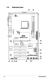
1.5.3 Motherboard layout 1 2 20.3cm(8.0in) KBMS ATX12V COM LPT CPU Socket DDR2-1066 DDR2 DIMM_A1 (64bit, 240-pin module) DDR2 DIMM_B1 (64bit, 240-pin module) EATXPWR 30.5cm(12.0in) 4PHASE POWER 5000HRS VRM USB34 LAN1_USB12 CPU_FAN AUDIO PCIEX1_1 M2N68 PLUS 1000M LAN Realtek PCIEX16 3 8211CL SATA RAID Lithium Cell 4 PCIEX1_2 CMOS Power PCI1 SB_PWR NVIDIA® MCP68 SE Super I/O SATA4 PCI2 SATA3 5 SATA2 ALC 662 AAFP PCI3 CD SPDIF_OUT PCI4 8Mb BIOS SATA1 6 CLRTC PRI_IDE SPEAKER 7 USB56 USB78 USB910 F_PANEL 8 14 13 12 11 10 9 1-6 ASUS M2N68 PLUS
1.5.3 Motherboard layout 1 2 20.3cm(8.0in) KBMS ATX12V COM LPT CPU Socket DDR2-1066 DDR2 DIMM_A1 (64bit, 240-pin module) DDR2 DIMM_B1 (64bit, 240-pin module) EATXPWR 30.5cm(12.0in) 4PHASE POWER 5000HRS VRM USB34 LAN1_USB12 CPU_FAN AUDIO PCIEX1_1 M2N68 PLUS 1000M LAN Realtek PCIEX16 3 8211CL SATA RAID Lithium Cell 4 PCIEX1_2 CMOS Power PCI1 SB_PWR NVIDIA® MCP68 SE Super I/O SATA4 PCI2 SATA3 5 SATA2 ALC 662 AAFP PCI3 CD SPDIF_OUT PCI4 8Mb BIOS SATA1 6 CLRTC PRI_IDE SPEAKER 7 USB56 USB78 USB910 F_PANEL 8 14 13 12 11 10 9 1-6 ASUS M2N68 PLUS

User Manual
Page 17
... USB78, USB910) 1-7 10. Onboard LED (SB_PWR) Page 1-23 1-20 1-17 1-22 1-17 1-20 1-4 1.6 Central Processing Unit (CPU) The motherboard comes with AMD® Opteron™ processors. IDE connector (40-1 pin PRI_IDE) Page Connectors/Jumpers/Slots 1-21 8. CPU Socket 4. Do not install an... Opteron™ processor on the motherboard. Locate the CPU socket on this motherboard. 1.6.1 Installing the CPU To install a CPU: 1. ATX power connectors (24-pin EATXPWR, 4-pin ATX12V) 2. System panel ...
... USB78, USB910) 1-7 10. Onboard LED (SB_PWR) Page 1-23 1-20 1-17 1-22 1-17 1-20 1-4 1.6 Central Processing Unit (CPU) The motherboard comes with AMD® Opteron™ processors. IDE connector (40-1 pin PRI_IDE) Page Connectors/Jumpers/Slots 1-21 8. CPU Socket 4. Do not install an... Opteron™ processor on the motherboard. Locate the CPU socket on this motherboard. 1.6.1 Installing the CPU To install a CPU: 1. ATX power connectors (24-pin EATXPWR, 4-pin ATX12V) 2. System panel ...
User Manual
Page 18
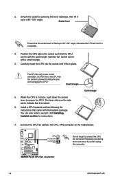
Socket lever Ensure that it up to secure the CPU. Small triangle 5. The lever clicks on the motherboard. DO NOT force the CPU into the socket until it fits in place, push down the socket lever to 90°-100° angle, otherwise ... the heatsink package. Gold triangle 7. Do not forget to a 90°-100° angle. Carefully insert the CPU into the socket to plug this connector. 1-8 ASUS M2N68 PLUS You can occur if you fail to prevent bending the pins and damaging the CPU! Hardware monitoring errors can also refer to indicate that the...
Socket lever Ensure that it up to secure the CPU. Small triangle 5. The lever clicks on the motherboard. DO NOT force the CPU into the socket until it fits in place, push down the socket lever to 90°-100° angle, otherwise ... the heatsink package. Gold triangle 7. Do not forget to a 90°-100° angle. Carefully insert the CPU into the socket to plug this connector. 1-8 ASUS M2N68 PLUS You can occur if you fail to prevent bending the pins and damaging the CPU! Hardware monitoring errors can also refer to indicate that the...
User Manual
Page 19
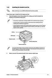
If the instructions in this section do not have to remove the retention module base when installing the CPU or installing other motherboard components. • If you purchased a separate CPU heatsink and fan assembly, make sure that you install the heatsink and fan assembly. 1.6.2 ...Installing the heatsink and fan Make sure that a Thermal Interface Material is already installed on the motherboard upon purchase. • You do not match the CPU documentation, follow the latter. 2. Attach one end of the installed CPU, making sure ...
If the instructions in this section do not have to remove the retention module base when installing the CPU or installing other motherboard components. • If you purchased a separate CPU heatsink and fan assembly, make sure that you install the heatsink and fan assembly. 1.6.2 ...Installing the heatsink and fan Make sure that a Thermal Interface Material is already installed on the motherboard upon purchase. • You do not match the CPU documentation, follow the latter. 2. Attach one end of the installed CPU, making sure ...
User Manual
Page 20
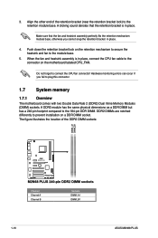
...to the retention module base. Align the other end of the DDR2 DIMM sockets: Channel Channel A Channel B 1-10 Sockets DIMM_A1 DIMM_B1 ASUS M2N68 PLUS When the fan and heatsink assembly is in place. Do not forget to the connector on a DDR DIMM socket. Hardware monitoring errors ...the CPU fan cable to connect the CPU fan connector! DDR2 DIMMs are notched differently to plug this connector. 1.7 System memory 1.7.1 Overview The motherboard comes with two Double Data Rate 2 (DDR2) Dual Inline Memory Modules (DIMM) sockets. Make sure that the retention bracket is in place....
...to the retention module base. Align the other end of the DDR2 DIMM sockets: Channel Channel A Channel B 1-10 Sockets DIMM_A1 DIMM_B1 ASUS M2N68 PLUS When the fan and heatsink assembly is in place. Do not forget to the connector on a DDR DIMM socket. Hardware monitoring errors ...the CPU fan cable to connect the CPU fan connector! DDR2 DIMMs are notched differently to plug this connector. 1.7 System memory 1.7.1 Overview The motherboard comes with two Double Data Rate 2 (DDR2) Dual Inline Memory Modules (DIMM) sockets. Make sure that the retention bracket is in place....
User Manual
Page 21
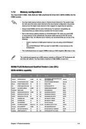
... any of the following: - Use a 64-bit Windows® OS if you want to install 4GB or more memory on the motherboard. • This motherboard does not support DIMMs made up to the memory address limitation on 32-bit Windows® OS, when you obtain memory modules from... OS can be about 3GB or less. Size SS/ DS CL Chip No. You may install varying memory sizes in Channel A and Channel B. M2N68 PLUS Motherboard Qualified Vendors Lists (QVL) DDR2-667MHz capability Vendor Part No. 1.7.2 Memory configurations You may install 512MB, 1GB, 2GB and 4GB unbuffered ECC/non-...
... any of the following: - Use a 64-bit Windows® OS if you want to install 4GB or more memory on the motherboard. • This motherboard does not support DIMMs made up to the memory address limitation on 32-bit Windows® OS, when you obtain memory modules from... OS can be about 3GB or less. Size SS/ DS CL Chip No. You may install varying memory sizes in Channel A and Channel B. M2N68 PLUS Motherboard Qualified Vendors Lists (QVL) DDR2-667MHz capability Vendor Part No. 1.7.2 Memory configurations You may install 512MB, 1GB, 2GB and 4GB unbuffered ECC/non-...

User Manual
Page 23
... on the socket such that it flips out with your fingers when pressing the retaining clips. Simultaneously press the retaining clips outward to both the motherboard and the components. 1. 1.7.3 Installing a DIMM Unplug the power supply before adding or removing DIMMs or other system components. Unlock a DDR2 DIMM socket by pressing the...
... on the socket such that it flips out with your fingers when pressing the retaining clips. Simultaneously press the retaining clips outward to both the motherboard and the components. 1. 1.7.3 Installing a DIMM Unplug the power supply before adding or removing DIMMs or other system components. Unlock a DDR2 DIMM socket by pressing the...
User Manual
Page 24
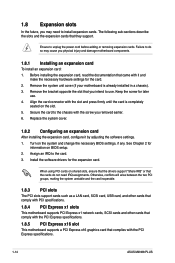
...the bracket opposite the slot that came with it by adjusting the software settings. 1. Remove the system unit cover (if your motherboard is completely seated on BIOS setup. 2. Keep the screw for the card. 2. Before installing the expansion card, read the ... cards that comply with PCI specifications. 1.8.4 PCI Express x1 slots This motherboard supports PCI Express x1 network cards, SCSI cards and other cards that comply with the PCI Express specifications. 1-14 ASUS M2N68 PLUS Replace the system cover. 1.8.2 Configuring an expansion card After installing the ...
...the bracket opposite the slot that came with it by adjusting the software settings. 1. Remove the system unit cover (if your motherboard is completely seated on BIOS setup. 2. Keep the screw for the card. 2. Before installing the expansion card, read the ... cards that comply with PCI specifications. 1.8.4 PCI Express x1 slots This motherboard supports PCI Express x1 network cards, SCSI cards and other cards that comply with the PCI Express specifications. 1-14 ASUS M2N68 PLUS Replace the system cover. 1.8.2 Configuring an expansion card After installing the ...
User Manual
Page 28
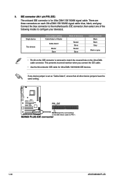
Connect the blue connector to the motherboard's IDE connector, then select one of device(s) - Single device Two devices Drive jumper setting Cable-Select or Master Cable-Select Master Slave Mode of the .... IDE connector (40-1 pin PRI_IDE) The onboard IDE connector is set as "Cable-Select", ensure that all other device jumpers have the same setting. 1-18 ASUS M2N68 PLUS This prevents incorrect insertion when you connect the IDE cable. • Use the 80-conductor IDE cable for Ultra DMA 133/100/66 signal cable...
Connect the blue connector to the motherboard's IDE connector, then select one of device(s) - Single device Two devices Drive jumper setting Cable-Select or Master Cable-Select Master Slave Mode of the .... IDE connector (40-1 pin PRI_IDE) The onboard IDE connector is set as "Cable-Select", ensure that all other device jumpers have the same setting. 1-18 ASUS M2N68 PLUS This prevents incorrect insertion when you connect the IDE cable. • Use the 80-conductor IDE cable for Ultra DMA 133/100/66 signal cable...
User Manual
Page 30
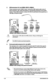
Never connect a 1394 cable to 480 Mbps connection speed. Doing so will damage the motherboard! Front panel audio connector (10-1 pin AAFP) This connector is for a chassis-mounted front panel audio I /O module cable to this connector. • We recommend that...USB 2.0 ports. USB connectors (10-1 pin USB56, USB 78, USB910) These connectors are for details. 1-20 ASUS M2N68 PLUS The USB 2.0 module is set the Front Panel Select item in the BIOS to avail of the motherboard high-definition audio capability. • By default, this connector, set to a slot opening at the back of...
Never connect a 1394 cable to 480 Mbps connection speed. Doing so will damage the motherboard! Front panel audio connector (10-1 pin AAFP) This connector is for a chassis-mounted front panel audio I /O module cable to this connector. • We recommend that...USB 2.0 ports. USB connectors (10-1 pin USB56, USB 78, USB910) These connectors are for details. 1-20 ASUS M2N68 PLUS The USB 2.0 module is set the Front Panel Select item in the BIOS to avail of the motherboard high-definition audio capability. • By default, this connector, set to a slot opening at the back of...


