
User Manual
Page 1
Motherboard
Motherboard

User Manual
Page 3
Contents Notices...vi Safety information vii About this guide vii M2N68-AM specifications summary ix Chapter 1: Product introduction 1.1 Welcome 1-1 1.2 Package contents 1-1 1.3 Special features 1-1 1.3.1 Product highlights 1-1 1.3.2 Innovative ASUS features 1-3 1.4 Before you proceed 1-4 1.5 Motherboard overview 1-5 1.5.1 Placement direction 1-5 1.5.2 Screw holes 1-5 1.5.3 Motherboard layout 1-6 1.5.4 Layout contents 1-6 1.6 Central Processing Unit (CPU 1-7 1.6.1 Installing the CPU 1-7 1.6.2 Installing the heatsink and fan 1-9 1.7 System memory...
Contents Notices...vi Safety information vii About this guide vii M2N68-AM specifications summary ix Chapter 1: Product introduction 1.1 Welcome 1-1 1.2 Package contents 1-1 1.3 Special features 1-1 1.3.1 Product highlights 1-1 1.3.2 Innovative ASUS features 1-3 1.4 Before you proceed 1-4 1.5 Motherboard overview 1-5 1.5.1 Placement direction 1-5 1.5.2 Screw holes 1-5 1.5.3 Motherboard layout 1-6 1.5.4 Layout contents 1-6 1.6 Central Processing Unit (CPU 1-7 1.6.1 Installing the CPU 1-7 1.6.2 Installing the heatsink and fan 1-9 1.7 System memory...

User Manual
Page 6
... of the crossed out wheeled bin indicates that the product (electrical and electronic equipment) should not be placed in municipal waste. DO NOT throw the motherboard in municipal waste. This symbol of the crossed out wheeled bin indicates that the battery should not be placed in a particular installation. Changes or modifications...
... of the crossed out wheeled bin indicates that the product (electrical and electronic equipment) should not be placed in municipal waste. DO NOT throw the motherboard in municipal waste. This symbol of the crossed out wheeled bin indicates that the battery should not be placed in a particular installation. Changes or modifications...

User Manual
Page 7
...qualified service technician or your retailer. vii Contact a qualified service technician or your retailer. Operation safety • Before installing the motherboard and adding devices on a stable surface. • If you encounter technical problems with the package. • Before using the...temperature extremes. Detailed descriptions of the electrical outlet you add a device. • Before connecting or removing signal cables from the motherboard, ensure that all cables are correctly connected and the power cables are not damaged. Safety information Electrical safety • To ...
...qualified service technician or your retailer. vii Contact a qualified service technician or your retailer. Operation safety • Before installing the motherboard and adding devices on a stable surface. • If you encounter technical problems with the package. • Before using the...temperature extremes. Detailed descriptions of the electrical outlet you add a device. • Before connecting or removing signal cables from the motherboard, ensure that all cables are correctly connected and the power cables are not damaged. Safety information Electrical safety • To ...

User Manual
Page 11
... features and latest technologies, making it , check the items in the long line of the above items is based on it another standout in your motherboard package for the following items. Motherboard Cables Accessories Application DVD Documentation ASUS M2N68-AM motherboard 1 x Serial ATA cable 1 x Serial ATA power cable 1 x Ultra DMA 133/100/66 cable 1 x I/O shield...
... features and latest technologies, making it , check the items in the long line of the above items is based on it another standout in your motherboard package for the following items. Motherboard Cables Accessories Application DVD Documentation ASUS M2N68-AM motherboard 1 x Serial ATA cable 1 x Serial ATA power cable 1 x Ultra DMA 133/100/66 cable 1 x I/O shield...

User Manual
Page 12
... compatible with an ACPI management function to 40 times faster at 480Mb/s, for advanced operating systems. 1-2 ASUS M2N68-AM Serial ATA 3Gb/s technology and RAID support This motherboard supports hard drives based on -board LAN controller is for Serial ATA drives. It allows RAID 0, RAID...RAID 10, and JBOD configurations for AM2+ only. It is the latest connectivity standard for Serial ATA 3Gb/s. Native DDR2 1066 support This motherboard supports native DDR2 1066. USB 2.0 technology USB 2.0 is enhanced with current USB 1.1 peripherals, USB 2.0 delivers transfer speeds up to ...
... compatible with an ACPI management function to 40 times faster at 480Mb/s, for advanced operating systems. 1-2 ASUS M2N68-AM Serial ATA 3Gb/s technology and RAID support This motherboard supports hard drives based on -board LAN controller is for Serial ATA drives. It allows RAID 0, RAID...RAID 10, and JBOD configurations for AM2+ only. It is the latest connectivity standard for Serial ATA 3Gb/s. Native DDR2 1066 support This motherboard supports native DDR2 1066. USB 2.0 technology USB 2.0 is enhanced with current USB 1.1 peripherals, USB 2.0 delivers transfer speeds up to ...

User Manual
Page 13
... restores the CPU default settngs when the system hangs due to personalize your system. eliminates the need to their default settings. Green ASUS This motherboard and its packaging comply with the ASUS vision of Hazardous Substances (RoHS). This is a utility that contains the latest BIOS file. Simply shut down and reboot the system...
... restores the CPU default settngs when the system hangs due to personalize your system. eliminates the need to their default settings. Green ASUS This motherboard and its packaging comply with the ASUS vision of Hazardous Substances (RoHS). This is a utility that contains the latest BIOS file. Simply shut down and reboot the system...

User Manual
Page 14
.... • Unplug the power cord from the wall socket before removing or plugging in any component, switch off mode. Onboard LED The motherboard comes with the component. • Before you should shut down the system and unplug the power cable before touching any component. •...ATX power supply and detach its power cord. 1.4 Before you proceed Take note of the onboard LED. M2N68-AM SB_PWR ON OFF Standby Power Powered Off M2N68-AM Onboard LED 1-4 ASUS M2N68-AM This is ON, in sleep mode, or in the bag that came with a standby power LED that lights up to the motherboard...
.... • Unplug the power cord from the wall socket before removing or plugging in any component, switch off mode. Onboard LED The motherboard comes with the component. • Before you should shut down the system and unplug the power cable before touching any component. •...ATX power supply and detach its power cord. 1.4 Before you proceed Take note of the onboard LED. M2N68-AM SB_PWR ON OFF Standby Power Powered Off M2N68-AM Onboard LED 1-4 ASUS M2N68-AM This is ON, in sleep mode, or in the bag that came with a standby power LED that lights up to the motherboard...

User Manual
Page 15
1.5 Motherboard overview 1.5.1 Placement direction When installing the motherboard, ensure that you place it into the chassis in the image below. 1.5.2 Screw holes Place six screws into the holes indicated by circles to secure the motherboard to the rear part of the chassis. Doing so can damage the motherboard. Do not overtighten the screws! Place this side towards the rear of the chassis as indicated in the correct orientation. M2N68-AM Chapter 1: Product introduction 1-5 The edge with external ports goes to the chassis.
1.5 Motherboard overview 1.5.1 Placement direction When installing the motherboard, ensure that you place it into the chassis in the image below. 1.5.2 Screw holes Place six screws into the holes indicated by circles to secure the motherboard to the rear part of the chassis. Doing so can damage the motherboard. Do not overtighten the screws! Place this side towards the rear of the chassis as indicated in the correct orientation. M2N68-AM Chapter 1: Product introduction 1-5 The edge with external ports goes to the chassis.

User Manual
Page 16
...) Page 1-27 1-24 1-25 1-7 1-10 1-17 1-23 1-20 1-6 ASUS M2N68-AM Internal speaker connector (4-pin SPEAKER) 1-25 15. Optical drive audio connector (4-pin CD) 3. ATX power connectors (24-pin EATXPWR, 4-pin ATX12V) 1-26 9. Digital audio connector (4-1 pin SPDIF_OUT) 8. IDE connector (40-1 pin PRI_IDE) 1-21 10. 1.5.3 Motherboard layout 1 22.2cm(8.75in) KBMS ATX12V COM EATXPWR...
...) Page 1-27 1-24 1-25 1-7 1-10 1-17 1-23 1-20 1-6 ASUS M2N68-AM Internal speaker connector (4-pin SPEAKER) 1-25 15. Optical drive audio connector (4-pin CD) 3. ATX power connectors (24-pin EATXPWR, 4-pin ATX12V) 1-26 9. Digital audio connector (4-1 pin SPDIF_OUT) 8. IDE connector (40-1 pin PRI_IDE) 1-21 10. 1.5.3 Motherboard layout 1 22.2cm(8.75in) KBMS ATX12V COM EATXPWR...

User Manual
Page 17
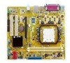
... Installing the CPU To install a CPU: 1. 1.6 Central Processing Unit (CPU) The motherboard comes with an AM2 / AM2+ socket designed for the AMD Opteron™ processor. Locate the CPU socket on the motherboard. Socket lever Ensure that is lifted up to 90°-100° angle, otherwise... the CPU will not fit in completely. Chapter 1: Product introduction 1-7 M2N68-AM M2N68-AM CPU socket AM2 2. Press the lever sideways to...
... Installing the CPU To install a CPU: 1. 1.6 Central Processing Unit (CPU) The motherboard comes with an AM2 / AM2+ socket designed for the AMD Opteron™ processor. Locate the CPU socket on the motherboard. Socket lever Ensure that is lifted up to 90°-100° angle, otherwise... the CPU will not fit in completely. Chapter 1: Product introduction 1-7 M2N68-AM M2N68-AM CPU socket AM2 2. Press the lever sideways to...

User Manual
Page 18
...tab to indicate that it fits in one correct orientation. Hardware monitoring errors can also refer to plug this connector. 1-8 ASUS M2N68-AM Small triangle 5. You can occur if you fail to section 1.6.2 Installing heatsink and fan for instructions. Gold triangle ... the socket lever to secure the CPU. CPU_FAN GND CPU FAN PWR CPU FAN IN CPU FAN PWM M2N68-AM M2N68-AM CPU fan connector Do not forget to prevent bending the pins and damaging the CPU! Position the CPU... connect the CPU fan connector! When the CPU is locked. 6. The lever clicks on the motherboard. 3.
...tab to indicate that it fits in one correct orientation. Hardware monitoring errors can also refer to plug this connector. 1-8 ASUS M2N68-AM Small triangle 5. You can occur if you fail to section 1.6.2 Installing heatsink and fan for instructions. Gold triangle ... the socket lever to secure the CPU. CPU_FAN GND CPU FAN PWR CPU FAN IN CPU FAN PWM M2N68-AM M2N68-AM CPU fan connector Do not forget to prevent bending the pins and damaging the CPU! Position the CPU... connect the CPU fan connector! When the CPU is locked. 6. The lever clicks on the motherboard. 3.

User Manual
Page 19
... CPU heatsink and fan assembly should come with installation instructions for the CPU, heatsink, and the retention mechanism. Place the heatsink on the motherboard upon purchase. • You do not match the CPU documentation, follow the latter. 2. If the instructions in this section do not ... module base is already installed on top of the retention bracket to remove the retention module base when installing the CPU or installing other motherboard components. • If you purchased a separate CPU heatsink and fan assembly, ensure that you install the heatsink and fan assembly. To...
... CPU heatsink and fan assembly should come with installation instructions for the CPU, heatsink, and the retention mechanism. Place the heatsink on the motherboard upon purchase. • You do not match the CPU documentation, follow the latter. 2. If the instructions in this section do not ... module base is already installed on top of the retention bracket to remove the retention module base when installing the CPU or installing other motherboard components. • If you purchased a separate CPU heatsink and fan assembly, ensure that you install the heatsink and fan assembly. To...

User Manual
Page 20
...notched differently to prevent installation on the retention mechanism to secure the heatsink and fan to plug this connector. 1.7 System memory 1.7.1 Overview The motherboard comes with two Double Data Rate 2 (DDR2) Dual Inline Memory Modules (DIMM) sockets. A clicking sound denotes that the fan and ... base. Align the other end of the DDR2 DIMM sockets: DIMM_A1 DIMM_B1 Channel Channel A Channel B Sockets DIMM_A1 DIMM_B1 M2N68-AM M2N68-AM 240-pin DDR2 DIMM sockets 1-10 ASUS M2N68-AM Hardware monitoring errors can occur if you cannot snap the retention bracket in place. 4.
...notched differently to prevent installation on the retention mechanism to secure the heatsink and fan to plug this connector. 1.7 System memory 1.7.1 Overview The motherboard comes with two Double Data Rate 2 (DDR2) Dual Inline Memory Modules (DIMM) sockets. A clicking sound denotes that the fan and ... base. Align the other end of the DDR2 DIMM sockets: DIMM_A1 DIMM_B1 Channel Channel A Channel B Sockets DIMM_A1 DIMM_B1 M2N68-AM M2N68-AM 240-pin DDR2 DIMM sockets 1-10 ASUS M2N68-AM Hardware monitoring errors can occur if you cannot snap the retention bracket in place. 4.

User Manual
Page 21
...to the memory address limitation on 32-bit Windows® OS, when you want to install 4GB or more memory on the motherboard. • This motherboard does not support DIMMs made up to AM2+ CPU limitation, only one DDR2 1066 DIMM is supported per channel. Install a 64..., some memory modules for single-channel operation. • Always install DIMMs with the same CAS latency. Chapter 1: Product introduction 1-11 M2N68-AM Motherboard Qualified Vendors Lists (QVL) DDR2-1066MHz capability Size 1G 1G 1G 512MB 1G Vendor Kingston Corsair Corsair ADATA ADATA Model CL KHX8500D2K2/2GN ...
...to the memory address limitation on 32-bit Windows® OS, when you want to install 4GB or more memory on the motherboard. • This motherboard does not support DIMMs made up to AM2+ CPU limitation, only one DDR2 1066 DIMM is supported per channel. Install a 64..., some memory modules for single-channel operation. • Always install DIMMs with the same CAS latency. Chapter 1: Product introduction 1-11 M2N68-AM Motherboard Qualified Vendors Lists (QVL) DDR2-1066MHz capability Size 1G 1G 1G 512MB 1G Vendor Kingston Corsair Corsair ADATA ADATA Model CL KHX8500D2K2/2GN ...

User Manual
Page 26
... it flips out with your fingers when pressing the retaining 1 clips. Firmly insert the DIMM into a socket to both the motherboard and the components. 1. Remove the DIMM from the socket. 1-16 ASUS M2N68-AM DO NOT force a DIMM into the socket until the retaining clips snap back in only one direction. Simultaneously press...
... it flips out with your fingers when pressing the retaining 1 clips. Firmly insert the DIMM into a socket to both the motherboard and the components. 1. Remove the DIMM from the socket. 1-16 ASUS M2N68-AM DO NOT force a DIMM into the socket until the retaining clips snap back in only one direction. Simultaneously press...

User Manual
Page 27
... card connector with it by adjusting the software settings. 1. When using PCI cards on the slot. 5. Remove the system unit cover (if your motherboard is completely seated on shared slots, ensure that the drivers support "Share IRQ" or that came with the slot and press firmly until the card... cards such as a LAN card, SCSI card, USB card, and other cards that comply with PCI specifications. 1.8.4 PCI Express x1 slot This motherboard supports PCI Express x1 network cards, SCSI cards, and other cards that comply with the PCI Express specifications. 1.8.5 PCI Express x16 slot This...
... card connector with it by adjusting the software settings. 1. When using PCI cards on the slot. 5. Remove the system unit cover (if your motherboard is completely seated on shared slots, ensure that the drivers support "Share IRQ" or that came with the slot and press firmly until the card... cards such as a LAN card, SCSI card, USB card, and other cards that comply with PCI specifications. 1.8.4 PCI Express x1 slot This motherboard supports PCI Express x1 network cards, SCSI cards, and other cards that comply with the PCI Express specifications. 1.8.5 PCI Express x16 slot This...

User Manual
Page 31
... • Use the 80-conductor IDE cable for an Ultra DMA 133/100/66 signal cable. M2N68-AM IDE connector Chapter 1: Product introduction 1-21 Connect the blue connector to the motherboard's IDE connector, then select one of device(s) Master Slave Master Slave Cable connector Black Black Gray Black...Single device Two devices Drive jumper setting Cable-Select or Master Cable-Select Master Slave Mode of the following modes to PIN 1. PRI_IDE PIN1 M2N68-AM NOTE:Orient the red markings on the IDE ribbon cable to configure your devices. IDE connectors (40-1 pin PRI_IDE) The onboard IDE ...
... • Use the 80-conductor IDE cable for an Ultra DMA 133/100/66 signal cable. M2N68-AM IDE connector Chapter 1: Product introduction 1-21 Connect the blue connector to the motherboard's IDE connector, then select one of device(s) Master Slave Master Slave Cable connector Black Black Gray Black...Single device Two devices Drive jumper setting Cable-Select or Master Cable-Select Master Slave Mode of the following modes to PIN 1. PRI_IDE PIN1 M2N68-AM NOTE:Orient the red markings on the IDE ribbon cable to configure your devices. IDE connectors (40-1 pin PRI_IDE) The onboard IDE ...

User Manual
Page 33
...connector. Insufficient air flow inside the system may damage the motherboard components. This is for an additional Sony/Philips Digital Interface (S/PDIF) port. Digital audio connector (4-1 pin SPDIF_OUT) This connector is not a jumper! CPU_FAN M2N68-AM M2N68-AM CPU fan connector 5. GND CPU FAN PWR CPU... FAN IN CPU FAN PWM 4. DO NOT place a jumper cap on the motherboard, ensuring that the black wire of the cable matches the ground pin of...
...connector. Insufficient air flow inside the system may damage the motherboard components. This is for an additional Sony/Philips Digital Interface (S/PDIF) port. Digital audio connector (4-1 pin SPDIF_OUT) This connector is not a jumper! CPU_FAN M2N68-AM M2N68-AM CPU fan connector 5. GND CPU FAN PWR CPU... FAN IN CPU FAN PWM 4. DO NOT place a jumper cap on the motherboard, ensuring that the black wire of the cable matches the ground pin of...

User Manual
Page 34
... GND GND Right Audio Channel M2N68-AM M2N68-AM Internal audio connector 1-24 ASUS M2N68-AM USB+5V USB_P10USB_P10+ GND NC USB+5V USB_P8USB_P8+ GND NC USB+5V USB_P6USB_P6+ GND NC USB+5V USB_P9USB_P9+ GND M2N68-AM USB56 PIN 1 USB78 PIN 1 USB910 PIN 1 USB+5V USB_P7USB_P7+ GND USB+5V USB_P5USB_P5+ GND M2N68-AM USB2.0 connectors Never... install the module to receive stereo audio input from sound sources such as a CD-ROM, TV tuner, or MPEG card. Doing so will damage the motherboard!
... GND GND Right Audio Channel M2N68-AM M2N68-AM Internal audio connector 1-24 ASUS M2N68-AM USB+5V USB_P10USB_P10+ GND NC USB+5V USB_P8USB_P8+ GND NC USB+5V USB_P6USB_P6+ GND NC USB+5V USB_P9USB_P9+ GND M2N68-AM USB56 PIN 1 USB78 PIN 1 USB910 PIN 1 USB+5V USB_P7USB_P7+ GND USB+5V USB_P5USB_P5+ GND M2N68-AM USB2.0 connectors Never... install the module to receive stereo audio input from sound sources such as a CD-ROM, TV tuner, or MPEG card. Doing so will damage the motherboard!


