
User Guide
Page 1
H81M-P PLUS Motherboard
H81M-P PLUS Motherboard
User Guide
Page 3
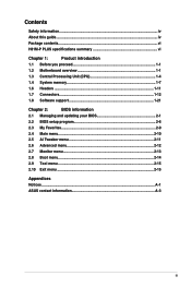
Contents Safety information...iv About this guide...iv Package contents...vi H81M-P PLUS specifications summary vi Chapter 1: Product introduction 1.1 Before you proceed 1-1 1.2 Motherboard overview 1-1 1.3 Central Processing Unit (CPU 1-4 1.4 System memory 1-7 1.6 Headers...1-11 1.7 Connectors 1-12 1.8 Software support 1-21 Chapter 2: ... 2-9 2.4 Main menu...2-10 2.5 Ai Tweaker menu 2-11 2.6 Advanced menu 2-12 2.7 Monitor menu 2-13 2.8 Boot menu...2-14 2.9 Tool menu...2-15 2.10 Exit menu...2-15 Appendices Notices...A-1 ASUS contact information A-3 iii
Contents Safety information...iv About this guide...iv Package contents...vi H81M-P PLUS specifications summary vi Chapter 1: Product introduction 1.1 Before you proceed 1-1 1.2 Motherboard overview 1-1 1.3 Central Processing Unit (CPU 1-4 1.4 System memory 1-7 1.6 Headers...1-11 1.7 Connectors 1-12 1.8 Software support 1-21 Chapter 2: ... 2-9 2.4 Main menu...2-10 2.5 Ai Tweaker menu 2-11 2.6 Advanced menu 2-12 2.7 Monitor menu 2-13 2.8 Boot menu...2-14 2.9 Tool menu...2-15 2.10 Exit menu...2-15 Appendices Notices...A-1 ASUS contact information A-3 iii

User Guide
Page 5
...emphasize a word or a phrase. Used to complete a task. These documents are linked with a plus sign (+). Typography Bold text Italics Indicates a menu or an item to the ASUS contact information. 2. If you must press two or more information Refer to the following symbols used in...you must press the enclosed key. + + Example: means that you complete a task. Refer to select. v ASUS websites The ASUS website provides updated information on ASUS hardware and software products. Conventions used throughout this guide To ensure that you must press the Enter or Return key....
...emphasize a word or a phrase. Used to complete a task. These documents are linked with a plus sign (+). Typography Bold text Italics Indicates a menu or an item to the ASUS contact information. 2. If you must press two or more information Refer to the following symbols used in...you must press the enclosed key. + + Example: means that you complete a task. Refer to select. v ASUS websites The ASUS website provides updated information on ASUS hardware and software products. Conventions used throughout this guide To ensure that you must press the Enter or Return key....

User Guide
Page 6
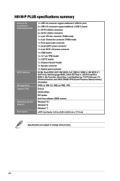
... mode will run at the maximum transfer rate of individual CPUs. Supports HDMI with max. H81M-P PLUS specifications summary CPU Chipset Memory Graphics Expansion slots LGA1150 socket for the following items. Motherboard Cables Accessories Application DVD Documentation ASUS H81M-P PLUS motherboard 2 x Serial ATA 6.0 Gb/s cables 1 x I/O Shield Support DVD User Guide If any of 1024MB 1 x PCI...
... mode will run at the maximum transfer rate of individual CPUs. Supports HDMI with max. H81M-P PLUS specifications summary CPU Chipset Memory Graphics Expansion slots LGA1150 socket for the following items. Motherboard Cables Accessories Application DVD Documentation ASUS H81M-P PLUS motherboard 2 x Serial ATA 6.0 Gb/s cables 1 x I/O Shield Support DVD User Guide If any of 1024MB 1 x PCI...

User Guide
Page 7
... 2 x USB 2.0 ports 1 x HDMI port 1 x DVI port 1 x D-Sub port 1 x LAN (RJ-45) port 3 x Audio jacks support 7.1-channel audio output (continued on the CPU installed. H81M-P PLUS specifications summary Storage LAN Audio USB ASUS unique features Back Panel I/O ports Intel® H81 Express Chipset: - 2 x Serial ATA 6.0 Gb/s connectors (yellow) - 2 x Serial ATA 3.0 Gb/s connectors (dark brown) -
... 2 x USB 2.0 ports 1 x HDMI port 1 x DVI port 1 x D-Sub port 1 x LAN (RJ-45) port 3 x Audio jacks support 7.1-channel audio output (continued on the CPU installed. H81M-P PLUS specifications summary Storage LAN Audio USB ASUS unique features Back Panel I/O ports Intel® H81 Express Chipset: - 2 x Serial ATA 6.0 Gb/s connectors (yellow) - 2 x Serial ATA 3.0 Gb/s connectors (dark brown) -
User Guide
Page 8
viii H81M-P PLUS specifications summary Internal I/O connectors/ buttons/switches BIOS features Manageability Support DVD Operating System Support Form factor 1 x USB 3.0 connector support additional 2 USB 3.0 ports 2 x USB 2.0 connectors support ... panel connector 64 Mb Flash ROM, UEFI AMI BIOS, PnP, DMI2.0, WfM2.0, SM BIOS 2.7, ACPI 2.0a, Multi-language BIOS, ASUS EZ Flash 2, ASUS CrashFree BIOS 3, My Favorites, Quick Note, Last Modified log, F12 PrintScreen, F3 Shortcut functions and ASUS DRAM SPD (Serial Presence Detect) memory information WfM 2.0, DMI 2.0, WOL by PME, PXE Drivers...
viii H81M-P PLUS specifications summary Internal I/O connectors/ buttons/switches BIOS features Manageability Support DVD Operating System Support Form factor 1 x USB 3.0 connector support additional 2 USB 3.0 ports 2 x USB 2.0 connectors support ... panel connector 64 Mb Flash ROM, UEFI AMI BIOS, PnP, DMI2.0, WfM2.0, SM BIOS 2.7, ACPI 2.0a, Multi-language BIOS, ASUS EZ Flash 2, ASUS CrashFree BIOS 3, My Favorites, Quick Note, Last Modified log, F12 PrintScreen, F3 Shortcut functions and ASUS DRAM SPD (Serial Presence Detect) memory information WfM 2.0, DMI 2.0, WOL by PME, PXE Drivers...

User Guide
Page 9
... the configuration of your chassis to ensure that you place it . Ensure that the motherboard fits into it into the chassis in the image below. ASUS H81M-P PLUS 1-1 Failure to do so may cause severe damage to do so can cause you physical injury and damage motherboard components. 1.2.1 Placement direction When installing the...
... the configuration of your chassis to ensure that you place it . Ensure that the motherboard fits into it into the chassis in the image below. ASUS H81M-P PLUS 1-1 Failure to do so may cause severe damage to do so can cause you physical injury and damage motherboard components. 1.2.1 Placement direction When installing the...

User Guide
Page 10
Place this side towards the rear of the chassis H81M-P PLUS 1-2 Chapter 1: Product introduction Do not overtighten the screws! 1.2.2 Screw holes Place six screws into the holes indicated by circles to secure the motherboard to the chassis. Doing so can damage the motherboard.
Place this side towards the rear of the chassis H81M-P PLUS 1-2 Chapter 1: Product introduction Do not overtighten the screws! 1.2.2 Screw holes Place six screws into the holes indicated by circles to secure the motherboard to the chassis. Doing so can damage the motherboard.

User Guide
Page 12
...~2 [yellow]) 11. Serial port connectors (10-1 pin COM) 4. DDR3 DIMM slots 6. USB 3.0 connectors (20-1 pin USB3_12) 12. H81M-P PLUS H81M-P PLUS CPU socket LGA1150 Unplug all power cables before installing the CPU. • Upon purchase of the motherboard, ensure that the PnP cap is missing...contacts resulting from incorrect CPU installation/removal, or misplacement/loss/incorrect removal of the PnP cap. 1-4 Chapter 1: Product introduction ASUS will process Return Merchandise Authorization (RMA) requests only if the motherboard comes with a surface mount LGA1150 socket designed for the ...
...~2 [yellow]) 11. Serial port connectors (10-1 pin COM) 4. DDR3 DIMM slots 6. USB 3.0 connectors (20-1 pin USB3_12) 12. H81M-P PLUS H81M-P PLUS CPU socket LGA1150 Unplug all power cables before installing the CPU. • Upon purchase of the motherboard, ensure that the PnP cap is missing...contacts resulting from incorrect CPU installation/removal, or misplacement/loss/incorrect removal of the PnP cap. 1-4 Chapter 1: Product introduction ASUS will process Return Merchandise Authorization (RMA) requests only if the motherboard comes with a surface mount LGA1150 socket designed for the ...

User Guide
Page 13
1.3.1 Installing the CPU 1 2 3 A B 4 C 5 A B ASUS H81M-P PLUS 1-5
1.3.1 Installing the CPU 1 2 3 A B 4 C 5 A B ASUS H81M-P PLUS 1-5

User Guide
Page 15
DIMM_A1 DIMM_B1 H81M-P PLUS Channel Channel A Channel B Sockets DIMM_A1 DIMM_B1 H81M-P PLUS 240-pin DDR3 DIMM sockets ASUS H81M-P PLUS 1-7 To uninstall the CPU heatsink and fan assembly 1 2 A B B A 1.4 System memory 1.4.1 Overview This motherboard comes with two Double Data Rate 3 (DDR3) Dual Inline Memory Module (DIMM) sockets. DO NOT install a DDR or DDR2 memory module to Intel® CPU spec, DIMM voltage below 1.65V is notched differently from a DDR or DDR2 module. A DDR3 module is recommended to protect the CPU. According to the DDR3 slot.
DIMM_A1 DIMM_B1 H81M-P PLUS Channel Channel A Channel B Sockets DIMM_A1 DIMM_B1 H81M-P PLUS 240-pin DDR3 DIMM sockets ASUS H81M-P PLUS 1-7 To uninstall the CPU heatsink and fan assembly 1 2 A B B A 1.4 System memory 1.4.1 Overview This motherboard comes with two Double Data Rate 3 (DDR3) Dual Inline Memory Module (DIMM) sockets. DO NOT install a DDR or DDR2 memory module to Intel® CPU spec, DIMM voltage below 1.65V is notched differently from a DDR or DDR2 module. A DDR3 module is recommended to protect the CPU. According to the DDR3 slot.

User Guide
Page 17
1.4.3 Installing a DIMM 1 2 3 To remove a DIMM B A ASUS H81M-P PLUS 1-9
1.4.3 Installing a DIMM 1 2 3 To remove a DIMM B A ASUS H81M-P PLUS 1-9

User Guide
Page 19
... values. After clearing the CMOS, reinstall the battery. • You do not help, remove the onboard battery and short the two pins again to overclocking. ASUS H81M-P PLUS 1-11 Clear RTC RAM (2-pin CLRTC) This header allows you to overclocking, use the CPU Parameter Recall (C.P.R.) feature. Plug the power cord and turn ON... CMOS RTC RAM data. The onboard button cell battery powers the RAM data in CMOS. 1.6 Headers 1. Use a metal object such as system passwords. +3V_BAT GND H81M-P PLUS CLRTC PIN 1 H81M-P PLUS Clear RTC RAM To erase the RTC RAM: 1.
... values. After clearing the CMOS, reinstall the battery. • You do not help, remove the onboard battery and short the two pins again to overclocking. ASUS H81M-P PLUS 1-11 Clear RTC RAM (2-pin CLRTC) This header allows you to overclocking, use the CPU Parameter Recall (C.P.R.) feature. Plug the power cord and turn ON... CMOS RTC RAM data. The onboard button cell battery powers the RAM data in CMOS. 1.6 Headers 1. Use a metal object such as system passwords. +3V_BAT GND H81M-P PLUS CLRTC PIN 1 H81M-P PLUS Clear RTC RAM To erase the RTC RAM: 1.

User Guide
Page 21
USB 3.0 ports 1 and 2. This port is for any DVI-D compatible device. ASUS H81M-P PLUS 1-13 DVI-D port. HDMI port. PS/2 keyboard port (purple). Side Speaker Out For an 7.1-channel speaker setup, refer to CRT and isn't compatible with DVI-I. ...
USB 3.0 ports 1 and 2. This port is for any DVI-D compatible device. ASUS H81M-P PLUS 1-13 DVI-D port. HDMI port. PS/2 keyboard port (purple). Side Speaker Out For an 7.1-channel speaker setup, refer to CRT and isn't compatible with DVI-I. ...
User Guide
Page 22
... I /O module cable to this connector, set the item to this connector. COM PIN 1 RXD DTR DSR CTS DCD TXD GND RTS RI H81M-P PLUS H81M-P PLUS Serial port connectors The COM module is for a serial (COM) port. Front panel audio connector (10-1 pin AAFP) This connector is purchased ... PIN 1 PIN 1 MIC2 MICPWR Line out_R NC Line out_L PORT1 L PORT1 R PORT2 R SENSE_SEND PORT2 L H81M-P PLUS HD-audio-compliant Legacy AC'97 pin definition compliant definition H81M-P PLUS Front panel audio connector • We recommend that supports either HD Audio or legacy AC`97 audio standard. If...
... I /O module cable to this connector, set the item to this connector. COM PIN 1 RXD DTR DSR CTS DCD TXD GND RTS RI H81M-P PLUS H81M-P PLUS Serial port connectors The COM module is for a serial (COM) port. Front panel audio connector (10-1 pin AAFP) This connector is purchased ... PIN 1 PIN 1 MIC2 MICPWR Line out_R NC Line out_L PORT1 L PORT1 R PORT2 R SENSE_SEND PORT2 L H81M-P PLUS HD-audio-compliant Legacy AC'97 pin definition compliant definition H81M-P PLUS Front panel audio connector • We recommend that supports either HD Audio or legacy AC`97 audio standard. If...

User Guide
Page 23
... CPU FAN PWM CPU FAN IN CPU FAN PWR GND H81M-P PLUS CHA_FAN +5V CHA FAN IN CHA FAN PWR GND H81M-P PLUS Fan connectors Do not forget to connect the fan cables to the fan connectors on the fan connectors! ASUS H81M-P PLUS 1-15 These are not jumpers! The CPU_FAN connector supports ...a CPU fan of the connector. Only the 4-pin CPU fan and chassis fan support the ASUS Fan Xpert feature. Insufficient air flow inside the system may ...
... CPU FAN PWM CPU FAN IN CPU FAN PWR GND H81M-P PLUS CHA_FAN +5V CHA FAN IN CHA FAN PWR GND H81M-P PLUS Fan connectors Do not forget to connect the fan cables to the fan connectors on the fan connectors! ASUS H81M-P PLUS 1-15 These are not jumpers! The CPU_FAN connector supports ...a CPU fan of the connector. Only the 4-pin CPU fan and chassis fan support the ASUS Fan Xpert feature. Insufficient air flow inside the system may ...

User Guide
Page 24
...connectors comply with USB 2.0. USB3_12 USB3+5V IntA_P1_SSRXIntA_P1_SSRX+ IntA_P1_SSTXGND IntA_P1_SSTX+ GND IntA_P1_DIntA_P1_D+ GND H81M-P PLUS PIN 1 USB3+5V IntA_P2_SSRXIntA_P2_SSRX+ GND IntA_P2_SSTXIntA_P2_SSTX+ GND IntA_P2_DIntA_P2_D+ H81M-P PLUS USB3.0 Front panel connector The USB 3.0 module is purchased separately. 5. USB 2.0 connectors...! USB56 USB910 USB+5V USB_P5USB_P5+ GND NC USB+5V USB_P9USB_P9+ GND NC H81M-P PLUS PIN 1 PIN 1 USB+5V USB_P6USB_P6+ GND USB+5V USB_P10USB_P10+ GND H81M-P PLUS USB2.0 connectors Never connect a 1394 cable to connect a USB 3.0 module for...
...connectors comply with USB 2.0. USB3_12 USB3+5V IntA_P1_SSRXIntA_P1_SSRX+ IntA_P1_SSTXGND IntA_P1_SSTX+ GND IntA_P1_DIntA_P1_D+ GND H81M-P PLUS PIN 1 USB3+5V IntA_P2_SSRXIntA_P2_SSRX+ GND IntA_P2_SSTXIntA_P2_SSTX+ GND IntA_P2_DIntA_P2_D+ H81M-P PLUS USB3.0 Front panel connector The USB 3.0 module is purchased separately. 5. USB 2.0 connectors...! USB56 USB910 USB+5V USB_P5USB_P5+ GND NC USB+5V USB_P9USB_P9+ GND NC H81M-P PLUS PIN 1 PIN 1 USB+5V USB_P6USB_P6+ GND USB+5V USB_P10USB_P10+ GND H81M-P PLUS USB2.0 connectors Never connect a 1394 cable to connect a USB 3.0 module for...

User Guide
Page 25
... has 24-pin and 4-pin power plugs. • DO NOT forget to hear system beeps and warnings. +5V GND GND Speaker Out SPEAKER H81M-P PLUS PIN 1 H81M-P PLUS Speaker Out connector ASUS H81M-P PLUS 1-17 Speaker connector (4-pin SPEAKER) The 4-pin connector is inadequate. • If you to connect the 4-pin ATX +12V power plug. ATX12V EATXPWR...
... has 24-pin and 4-pin power plugs. • DO NOT forget to hear system beeps and warnings. +5V GND GND Speaker Out SPEAKER H81M-P PLUS PIN 1 H81M-P PLUS Speaker Out connector ASUS H81M-P PLUS 1-17 Speaker connector (4-pin SPEAKER) The 4-pin connector is inadequate. • If you to connect the 4-pin ATX +12V power plug. ATX12V EATXPWR...

User Guide
Page 26
...via Serial ATA 3.0 Gb/s signal cables. GND RSATA_RXP1 RSATA_RXN1 GND RSATA_TXN1 RSATA_TXP1 GND GND RSATA_RXP2 RSATA_RXN2 GND RSATA_TXN2 RSATA_TXP2 GND H81M-P PLUS SATA3G_1 SATA3G_2 H81M-P PLUS SATA 3.0Gb/s connectors When using hot-plug and NCQ, set the SATA Mode Selection item in the BIOS to [AHCI...]. 9. GND RSATA_RXP1 RSATA_RXN1 GND RSATA_TXN1 RSATA_TXP1 GND GND RSATA_RXP2 RSATA_RXN2 GND RSATA_TXN2 RSATA_TXP2 GND H81M-P PLUS SATA6G_1 SATA6G_2 H81M-P PLUS SATA 6.0Gb/s connectors When using hot-plug and NCQ, set the SATA Mode Selection item in the BIOS to ...
...via Serial ATA 3.0 Gb/s signal cables. GND RSATA_RXP1 RSATA_RXN1 GND RSATA_TXN1 RSATA_TXP1 GND GND RSATA_RXP2 RSATA_RXN2 GND RSATA_TXN2 RSATA_TXP2 GND H81M-P PLUS SATA3G_1 SATA3G_2 H81M-P PLUS SATA 3.0Gb/s connectors When using hot-plug and NCQ, set the SATA Mode Selection item in the BIOS to [AHCI...]. 9. GND RSATA_RXP1 RSATA_RXN1 GND RSATA_TXN1 RSATA_TXP1 GND GND RSATA_RXP2 RSATA_RXN2 GND RSATA_TXN2 RSATA_TXP2 GND H81M-P PLUS SATA6G_1 SATA6G_2 H81M-P PLUS SATA 6.0Gb/s connectors When using hot-plug and NCQ, set the SATA Mode Selection item in the BIOS to ...

User Guide
Page 27
... intrusion connector 11. F_CLKRUN F_SERIRQ F_FRAME# F_LAD3 F_LAD2 F_LAD1 F_LAD0 +3VSB S_PCIRST#_TBD GND C_PCICLK_TPM +3V +3V ASUS H81M-P PLUS 1-19 TPM connector (14-1 pin TPM) This connector supports a Trusted Platform Module (TPM) system, which can securely store keys, digital...as a chassis intrusion event. A TPM system also helps enhance network security, protects digital identities, and ensures platform integrity. TPM PIN 1 H81M-P PLUS H81M-P PLUS TPM connector The TPM module is removed or replaced. +5VSB_MB Chassis Signal GND 10. Connect one end of the chassis intrusion sensor or ...
... intrusion connector 11. F_CLKRUN F_SERIRQ F_FRAME# F_LAD3 F_LAD2 F_LAD1 F_LAD0 +3VSB S_PCIRST#_TBD GND C_PCICLK_TPM +3V +3V ASUS H81M-P PLUS 1-19 TPM connector (14-1 pin TPM) This connector supports a Trusted Platform Module (TPM) system, which can securely store keys, digital...as a chassis intrusion event. A TPM system also helps enhance network security, protects digital identities, and ensures platform integrity. TPM PIN 1 H81M-P PLUS H81M-P PLUS TPM connector The TPM module is removed or replaced. +5VSB_MB Chassis Signal GND 10. Connect one end of the chassis intrusion sensor or ...


