
User Manual
Page 1
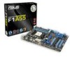
F1A55 Motherboard
F1A55 Motherboard
User Manual
Page 3
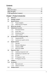
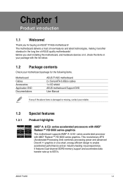
Contents Notices...vi Safety information vii About this guide viii F1A55 specifications summary ix Chapter 1: Product introduction 1.1 Welcome 1-1 1.2 Package contents 1-1 1.3 Special features 1-1 1.3.1 Product highlights 1-1 1.3.2 ASUS Exclusive Features 1-2 1.4 Before you proceed 1-4 1.5 Motherboard overview 1-5 1.5.1 Placement direction 1-5 1.5.2 Screw holes 1-5 1.5.3 Motherboard layout 1-6 1.5.4 Layout contents 1-6 1.6 Accelerated Processing Unit (APU 1-7 1.6.1 Installing the APU 1-7 1.6.2 Installing the heatsink and fan 1-9 1.7 System memory 1-10...
Contents Notices...vi Safety information vii About this guide viii F1A55 specifications summary ix Chapter 1: Product introduction 1.1 Welcome 1-1 1.2 Package contents 1-1 1.3 Special features 1-1 1.3.1 Product highlights 1-1 1.3.2 ASUS Exclusive Features 1-2 1.4 Before you proceed 1-4 1.5 Motherboard overview 1-5 1.5.1 Placement direction 1-5 1.5.2 Screw holes 1-5 1.5.3 Motherboard layout 1-6 1.5.4 Layout contents 1-6 1.6 Accelerated Processing Unit (APU 1-7 1.6.1 Installing the APU 1-7 1.6.2 Installing the heatsink and fan 1-9 1.7 System memory 1-10...
User Manual
Page 7
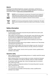
...and the power cables are unplugged. • Seek professional assistance before you are connected. If possible, disconnect all power cables from the motherboard, ensure that the battery should not be placed in any damage, contact your dealer immediately. • To avoid short circuits, keep ...published the chemical substances in municipal waste. DO NOT throw the mercury-containing button cell battery in our products at ASUS REACH website at http://csr.asus.com/english/REACH.htm. Safety information Electrical safety • To prevent electric shock hazard, disconnect the power cable...
...and the power cables are unplugged. • Seek professional assistance before you are connected. If possible, disconnect all power cables from the motherboard, ensure that the battery should not be placed in any damage, contact your dealer immediately. • To avoid short circuits, keep ...published the chemical substances in municipal waste. DO NOT throw the mercury-containing button cell battery in our products at ASUS REACH website at http://csr.asus.com/english/REACH.htm. Safety information Electrical safety • To prevent electric shock hazard, disconnect the power cable...
User Manual
Page 8
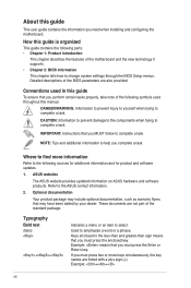
...press the Enter or Return key. Where to find more keys simultaneously, the key names are also provided. ASUS websites The ASUS website provides updated information on ASUS hardware and software products. Optional documentation Your product package may have been added by your dealer. Used to ...1. IMPORTANT: Instructions that may include optional documentation, such as warranty flyers, that you need when installing and configuring the motherboard. About this guide This user guide contains the information you MUST follow to complete a task. These documents are not part of the...
...press the Enter or Return key. Where to find more keys simultaneously, the key names are also provided. ASUS websites The ASUS website provides updated information on ASUS hardware and software products. Optional documentation Your product package may have been added by your dealer. Used to ...1. IMPORTANT: Instructions that may include optional documentation, such as warranty flyers, that you need when installing and configuring the motherboard. About this guide This user guide contains the information you MUST follow to complete a task. These documents are not part of the...
User Manual
Page 13
... AMD® A- & E2- series accelerated processors with AMD® Radeon™ HD 6000 series graphics. ASUS F1A55 1-1 Chapter 1 Product introduction 1.1 Welcome! Before you for the following items. Motherboard Cables Accessories Application DVD Documentations ASUS F1A55 motherboard 2 x Serial ATA 3.0Gb/s cables 1 x I/O shield ASUS motherboard Support DVD User Manual If any of new features and latest technologies, making it , check...
... AMD® A- & E2- series accelerated processors with AMD® Radeon™ HD 6000 series graphics. ASUS F1A55 1-1 Chapter 1 Product introduction 1.1 Welcome! Before you for the following items. Motherboard Cables Accessories Application DVD Documentations ASUS F1A55 motherboard 2 x Serial ATA 3.0Gb/s cables 1 x I/O shield ASUS motherboard Support DVD User Manual If any of new features and latest technologies, making it , check...

User Manual
Page 14
... A55 FCH (Hudson D2) is also backward compatible with USB 2.0 components. 100% All High-quality Conductive Polymer Capacitors This motherboard uses all high-quality conductive polymer capacitors for experienced performance enthusiasts that goes beyond traditional keyboardonly BIOS controls to enable more flexible ... and peripherals, USB 3.0 transfers data 10x faster and is designed to support up and running in different scenarios. ASUS Exclusive Features ASUS TurboV Feel the adrenaline rush of the button to get high quality images. The exclusive EZ Mode displays frequently-accessed...
... A55 FCH (Hudson D2) is also backward compatible with USB 2.0 components. 100% All High-quality Conductive Polymer Capacitors This motherboard uses all high-quality conductive polymer capacitors for experienced performance enthusiasts that goes beyond traditional keyboardonly BIOS controls to enable more flexible ... and peripherals, USB 3.0 transfers data 10x faster and is designed to support up and running in different scenarios. ASUS Exclusive Features ASUS TurboV Feel the adrenaline rush of the button to get high quality images. The exclusive EZ Mode displays frequently-accessed...
User Manual
Page 15
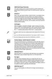
...by different climate conditions in -one simple to switch back and forth between different utilities. ASUS Anti-Surge Protection This special design protects expensive devices and the motherboard from switching power supply unit (PSU). It allows you to personalize your PC's loading...exchange. With its fast user-friendly interface, ASUS AI Suite II consolidates all -in different geographic regions and your system. The built-in variety of useful profiles offer flexible controls of USB3.0 fast charging experience. ASUS F1A55 1-3 Fanless Design: stylish heatsink solution The ...
...by different climate conditions in -one simple to switch back and forth between different utilities. ASUS Anti-Surge Protection This special design protects expensive devices and the motherboard from switching power supply unit (PSU). It allows you to personalize your PC's loading...exchange. With its fast user-friendly interface, ASUS AI Suite II consolidates all -in different geographic regions and your system. The built-in variety of useful profiles offer flexible controls of USB3.0 fast charging experience. ASUS F1A55 1-3 Fanless Design: stylish heatsink solution The ...
User Manual
Page 16
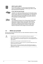
...the CPU default settings when the system hangs due to the motherboard, peripherals, or components. 1-4 Chapter 1: Product introduction Failure to do so may cause severe damage to overclocking failure. C.P.R. ASUS CrashFree BIOS 3 ASUS CrashFree BIOS 3 is an auto-recovery tool that allows you... product and thus mitigate environmental impacts. 1.4 Before you proceed Take note of the following precautions before you install motherboard components or change any motherboard settings. • Unplug the power cord from the wall socket before touching any component. • Before handling...
...the CPU default settings when the system hangs due to the motherboard, peripherals, or components. 1-4 Chapter 1: Product introduction Failure to do so may cause severe damage to overclocking failure. C.P.R. ASUS CrashFree BIOS 3 ASUS CrashFree BIOS 3 is an auto-recovery tool that allows you... product and thus mitigate environmental impacts. 1.4 Before you proceed Take note of the following precautions before you install motherboard components or change any motherboard settings. • Unplug the power cord from the wall socket before touching any component. • Before handling...
User Manual
Page 17
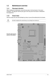
Place this side towards the rear of the chassis as indicated in the correct orientation. F1A55 ASUS F1A55 1-5 DO NOT overtighten the screws! Doing so can damage the motherboard. The edge with external ports goes to the chassis. 1.5 Motherboard overview 1.5.1 Placement direction When installing the motherboard, ensure that you place it into the chassis in the image below. 1.5.2 Screw holes Place six screws into the holes indicated by circles to secure the motherboard to the rear part of the chassis.
Place this side towards the rear of the chassis as indicated in the correct orientation. F1A55 ASUS F1A55 1-5 DO NOT overtighten the screws! Doing so can damage the motherboard. The edge with external ports goes to the chassis. 1.5 Motherboard overview 1.5.1 Placement direction When installing the motherboard, ensure that you place it into the chassis in the image below. 1.5.2 Screw holes Place six screws into the holes indicated by circles to secure the motherboard to the rear part of the chassis.
User Manual
Page 18
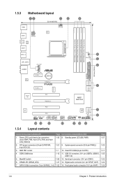
...~6) Page 1-20 1-21 1-7 1-10 1-26 1-27 1-22 Connectors/Jumpers/Slots/LED 8. Serial port connector (10-1 pin COM1) 13. 1.5.3 Motherboard layout 12 1 3 22.4cm(8.8in) KBMS USB56 ATX12V CPU_FAN EPU SPDIF_O2 ASM 1042 USB34 SOCKET FM1 USB3_12 LAN1_USB12 AUDIO RTL 8111E CHA_FAN1 PWR_FAN PCIEX1_1... Lithium Cell CMOS Power PCIEX1_2 PCIEX16_1 F1A55 DDR3 DIMM_A1 (64bit, 240-pin module) DDR3 DIMM_A2 (64bit, 240-pin module) DDR3 DIMM_B1 (64bit, 240-pin module) DDR3...
...~6) Page 1-20 1-21 1-7 1-10 1-26 1-27 1-22 Connectors/Jumpers/Slots/LED 8. Serial port connector (10-1 pin COM1) 13. 1.5.3 Motherboard layout 12 1 3 22.4cm(8.8in) KBMS USB56 ATX12V CPU_FAN EPU SPDIF_O2 ASM 1042 USB34 SOCKET FM1 USB3_12 LAN1_USB12 AUDIO RTL 8111E CHA_FAN1 PWR_FAN PCIEX1_1... Lithium Cell CMOS Power PCIEX1_2 PCIEX16_1 F1A55 DDR3 DIMM_A1 (64bit, 240-pin module) DDR3 DIMM_A2 (64bit, 240-pin module) DDR3 DIMM_B1 (64bit, 240-pin module) DDR3...
User Manual
Page 19
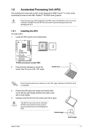
...orientation. F1A55 F1A55 processor socket FM1 2. Small triangle Gold triangle ASUS F1A55 1-7 otherwise, the APU will not fit in place. The APU fits in one correct orientation. Carefully insert the APU into the socket to a 90°-100° angle; 1.6 Accelerated Processing Unit (APU) This motherboard comes ...prevent bending the pins and damaging the APU! 1.6.1 Installing the APU To install a APU: 1. Locate the FM1 socket on the motherboard. Socket lever Ensure that the APU corner with the gold triangle matches the socket corner with AMD® Radeon™ HD 6000 ...
...orientation. F1A55 F1A55 processor socket FM1 2. Small triangle Gold triangle ASUS F1A55 1-7 otherwise, the APU will not fit in place. The APU fits in one correct orientation. Carefully insert the APU into the socket to a 90°-100° angle; 1.6 Accelerated Processing Unit (APU) This motherboard comes ...prevent bending the pins and damaging the APU! 1.6.1 Installing the APU To install a APU: 1. Locate the FM1 socket on the motherboard. Socket lever Ensure that the APU corner with the gold triangle matches the socket corner with AMD® Radeon™ HD 6000 ...
User Manual
Page 20
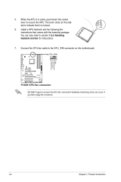
... to the CPU_FAN connector on the side tab to indicate that comes with the heatsink package. When the APU is locked. 6. CPU_FAN F1A55 F1A55 CPU fan connector DO NOT forget to plug this connector. The lever clicks on the motherboard. CPU FAN PWM CPU FAN IN CPU FAN PWR GND 1-8 Chapter 1: Product introduction
... to the CPU_FAN connector on the side tab to indicate that comes with the heatsink package. When the APU is locked. 6. CPU_FAN F1A55 F1A55 CPU fan connector DO NOT forget to plug this connector. The lever clicks on the motherboard. CPU FAN PWM CPU FAN IN CPU FAN PWR GND 1-8 Chapter 1: Product introduction
User Manual
Page 21
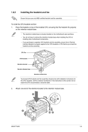
... fan assembly, ensure that a Thermal Interface Material is already installed on the motherboard upon purchase. • You do not match the CPU documentation, follow the latter. 2. Place the heatsink on top of the retention bracket to the retention module base. 1 2 3 4 5 ASUS F1A55 1-9 Attach one end of the installed CPU, ensuring that you use...
... fan assembly, ensure that a Thermal Interface Material is already installed on the motherboard upon purchase. • You do not match the CPU documentation, follow the latter. 2. Place the heatsink on top of the retention bracket to the retention module base. 1 2 3 4 5 ASUS F1A55 1-9 Attach one end of the installed CPU, ensuring that you use...
User Manual
Page 22
...DIMM_B1 and DIMM_B2 F1A55 240-pin DDR3 DIMM sockets 1-10 Chapter 1: Product introduction DO NOT forget to the retention module base. Ensure that the retention bracket is in place, connect the CPU fan cable to plug this connector. 1.7 System memory 1.7.1 Overview This motherboard comes with less ...place. Push down the retention bracket lock on the retention mechanism to secure the heatsink and fan to prevent installation on the motherboard labeled CPU_FAN. A clicking sound denotes that the fan and heatsink assembly perfectly fits the retention mechanism module base, otherwise you ...
...DIMM_B1 and DIMM_B2 F1A55 240-pin DDR3 DIMM sockets 1-10 Chapter 1: Product introduction DO NOT forget to the retention module base. Ensure that the retention bracket is in place, connect the CPU fan cable to plug this connector. 1.7 System memory 1.7.1 Overview This motherboard comes with less ...place. Push down the retention bracket lock on the retention mechanism to secure the heatsink and fan to prevent installation on the motherboard labeled CPU_FAN. A clicking sound denotes that the fan and heatsink assembly perfectly fits the retention mechanism module base, otherwise you ...
User Manual
Page 23
...the DIMMs are available in Channel A and Channel B. ASUS F1A55 1-11 Use a 64-bit �W�i�nd�o�w��s® OS if you want to install 4GB or more memory on the motherboard. • This motherboard does not support DIMMs made up of 512 megabits (...some memory modules for overclocking may install varying memory sizes in the market. • The default memory operation frequency is dependent on the motherboard, the actual usable memory for the OS can be about 3GB or less. 1.7.2 Memory configurations You may install 1GB, 2GB, and 4GB...
...the DIMMs are available in Channel A and Channel B. ASUS F1A55 1-11 Use a 64-bit �W�i�nd�o�w��s® OS if you want to install 4GB or more memory on the motherboard. • This motherboard does not support DIMMs made up of 512 megabits (...some memory modules for overclocking may install varying memory sizes in the market. • The default memory operation frequency is dependent on the motherboard, the actual usable memory for the OS can be about 3GB or less. 1.7.2 Memory configurations You may install 1GB, 2GB, and 4GB...
User Manual
Page 24
...) DS - - 8-8-8-24 1.65V • • Super Talent WA160UX6G9 6GB(3 x 2GB) DS - - 9 - • • • 1-12 Chapter 1: Product introduction Size SS/ DS Chip Brand Chip NO. F1A55 Motherboard Qualified Vendors Lists (QVL) DDR3-1866MHz capability Vendors Part No. Timing Voltage DIMM socket support (Optional) A* B* C* CORSAIR CMT4GX3M2A1866C9(XMP) 4GB(2 x 2GB) DS - - 9-9-9-24 1.65V •...
...) DS - - 8-8-8-24 1.65V • • Super Talent WA160UX6G9 6GB(3 x 2GB) DS - - 9 - • • • 1-12 Chapter 1: Product introduction Size SS/ DS Chip Brand Chip NO. F1A55 Motherboard Qualified Vendors Lists (QVL) DDR3-1866MHz capability Vendors Part No. Timing Voltage DIMM socket support (Optional) A* B* C* CORSAIR CMT4GX3M2A1866C9(XMP) 4GB(2 x 2GB) DS - - 9-9-9-24 1.65V •...
User Manual
Page 27
...DIMM matches the DIMM slot key on the socket. 2 DIMM notch 1 1 Unlocked retaining clip DIMM slot key A DIMM is properly seated. DIMM notch ASUS F1A55 1-15 Locked Retaining Clip 1.7.4 Removing a DIMM To remove a DIMM: 1. Remove the DIMM from the socket. Align a DIMM on the socket such... Installing a DIMM Unplug the power supply before adding or removing DIMMs or other system components. Press the retaining clips outward to both the motherboard and the components. 1. DO NOT force a DIMM into the socket until the retaining clips snap back in the wrong direction to unlock the...
...DIMM matches the DIMM slot key on the socket. 2 DIMM notch 1 1 Unlocked retaining clip DIMM slot key A DIMM is properly seated. DIMM notch ASUS F1A55 1-15 Locked Retaining Clip 1.7.4 Removing a DIMM To remove a DIMM: 1. Remove the DIMM from the socket. Align a DIMM on the socket such... Installing a DIMM Unplug the power supply before adding or removing DIMMs or other system components. Press the retaining clips outward to both the motherboard and the components. 1. DO NOT force a DIMM into the socket until the retaining clips snap back in the wrong direction to unlock the...
User Manual
Page 28
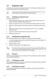
...and press firmly until the card is already installed in a chassis). 3. 1.8 Expansion slots In the future, you physical injury and damage motherboard components. 1.8.1 Installing an expansion card To install an expansion card: 1. Before installing the expansion card, read the documentation that you removed ...earlier. 6. Remove the system unit cover (if your motherboard is completely seated on the system and change the necessary BIOS settings, if any. Align the card connector with the PCI Express ...
...and press firmly until the card is already installed in a chassis). 3. 1.8 Expansion slots In the future, you physical injury and damage motherboard components. 1.8.1 Installing an expansion card To install an expansion card: 1. Before installing the expansion card, read the documentation that you removed ...earlier. 6. Remove the system unit cover (if your motherboard is completely seated on the system and change the necessary BIOS settings, if any. Align the card connector with the PCI Express ...
User Manual
Page 29
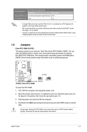
... RTC RAM CLRTC 12 23 Normal (Default) Clear RTC To erase the RTC RAM: 1. ASUS F1A55 1-17 Turn OFF the computer and unplug the power cord. 2. See page 1-21 for details. • Connect a chassis fan to the motherboard connector labeled CHA_FAN1/2 when using multiple graphics cards for a PCI Express x16 graphics card to...
... RTC RAM CLRTC 12 23 Normal (Default) Clear RTC To erase the RTC RAM: 1. ASUS F1A55 1-17 Turn OFF the computer and unplug the power cord. 2. See page 1-21 for details. • Connect a chassis fan to the motherboard connector labeled CHA_FAN1/2 when using multiple graphics cards for a PCI Express x16 graphics card to...
User Manual
Page 32
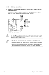
...ground pin of maximum 2A (24 W) fan power. • Only the CPU_FAN and CHA_FAN1/2 connectors support the ASUS Fan Xpert feature. • If you plug the rear chassis fan cable to the motherboard connector labeled CHA_FAN1/2 for better thermal environment. 1-20 Chapter 1: Product introduction Power, CPU and chassis fan connectors ...CPU FAN PWR GND CHA_FAN1 GND CHA FAN PWR CHA FAN IN CHA FAN PWM PWR_FAN CHA_FAN2 GND +12V F1A55 Rotation CHA FAN PWM CHA FAN IN CHA FAN PWR GND F1A55 fan connectors DO NOT forget to connect the fan cables to the fan connectors on the fan connectors. ...
...ground pin of maximum 2A (24 W) fan power. • Only the CPU_FAN and CHA_FAN1/2 connectors support the ASUS Fan Xpert feature. • If you plug the rear chassis fan cable to the motherboard connector labeled CHA_FAN1/2 for better thermal environment. 1-20 Chapter 1: Product introduction Power, CPU and chassis fan connectors ...CPU FAN PWR GND CHA_FAN1 GND CHA FAN PWR CHA FAN IN CHA FAN PWM PWR_FAN CHA_FAN2 GND +12V F1A55 Rotation CHA FAN PWM CHA FAN IN CHA FAN PWR GND F1A55 fan connectors DO NOT forget to connect the fan cables to the fan connectors on the fan connectors. ...


