
User Guide
Page 1
Motherboard F1A55-M LX3 R2.0 Series • F1A55-M LX3 R2.0 • F1A55-M LX3 PLUS R2.0
Motherboard F1A55-M LX3 R2.0 Series • F1A55-M LX3 R2.0 • F1A55-M LX3 PLUS R2.0
User Guide
Page 9
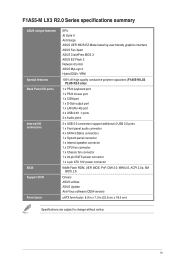
... BIOS Support DVD Form factor EPU AI Suite II Anti-Surge ASUS UEFI BIOS EZ Mode featuring user-friendly graphics interface ASUS Fan Xpert ASUS CrashFree BIOS 3 ASUS EZ Flash 2 Network iControl ASUS MyLogo 2 Hybrid DIGI+ VRM 100% All high quality conductive polymer capacitors (F1A55-M LX3 PLUS R2.0 only) 1 x PS/2 keyboard port 1 x PS/2 mouse port 1 x COM port 1 x D-Sub...
... BIOS Support DVD Form factor EPU AI Suite II Anti-Surge ASUS UEFI BIOS EZ Mode featuring user-friendly graphics interface ASUS Fan Xpert ASUS CrashFree BIOS 3 ASUS EZ Flash 2 Network iControl ASUS MyLogo 2 Hybrid DIGI+ VRM 100% All high quality conductive polymer capacitors (F1A55-M LX3 PLUS R2.0 only) 1 x PS/2 keyboard port 1 x PS/2 mouse port 1 x COM port 1 x D-Sub...
User Guide
Page 10
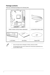
....6cm(8.9in) VGA KBPWR USB34 LAN_USB12 CHA_FAN Super I/O USBPW1-4 AUDIO AR 8161 ALC 887 F1A55-M LX3 PLUS R2.0 PCIEX16 PCIEX1_1 Lithium Cell CMOS Power AAFP PCI1 USBPW5-8 CLRTC USB78 SB_PWR USB56 64Mb BIOS AMD® A55 SATA3G_2 SPEAKER F_PANEL SATA3G_1 ASUS F1A55-M LX3 R2.0 Series motherboard User Manual 2 x Serial ATA 3.0 Gb/s cables 1 x I/O Shield User Guide Support...
....6cm(8.9in) VGA KBPWR USB34 LAN_USB12 CHA_FAN Super I/O USBPW1-4 AUDIO AR 8161 ALC 887 F1A55-M LX3 PLUS R2.0 PCIEX16 PCIEX1_1 Lithium Cell CMOS Power AAFP PCI1 USBPW5-8 CLRTC USB78 SB_PWR USB56 64Mb BIOS AMD® A55 SATA3G_2 SPEAKER F_PANEL SATA3G_1 ASUS F1A55-M LX3 R2.0 Series motherboard User Manual 2 x Serial ATA 3.0 Gb/s cables 1 x I/O Shield User Guide Support...
User Guide
Page 11
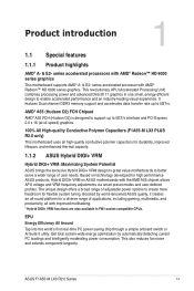
... memory support and accelerates data transfer rate up to create more headroom for high performance ASUS products, Hybrid DIGI+ VRM on technology developed for flexible system tuning. ASUS F1A55-M LX3 R2.0 Series 1-1 This also reduces fan noise and extends component longevity. series accelerated ...Potential ASUS brings the exclusive Hybrid DIGI+ VRM design to great value motherboards to better serve a wider range of adjustable power options to 5GT/s interface and PCI Express 2.0 x 16 (at x4 speed) graphics. 100% All High-quality Conductive Polymer Capacitors (F1A55-M LX3 PLUS R2...
... memory support and accelerates data transfer rate up to create more headroom for high performance ASUS products, Hybrid DIGI+ VRM on technology developed for flexible system tuning. ASUS F1A55-M LX3 R2.0 Series 1-1 This also reduces fan noise and extends component longevity. series accelerated ...Potential ASUS brings the exclusive Hybrid DIGI+ VRM design to great value motherboards to better serve a wider range of adjustable power options to 5GT/s interface and PCI Express 2.0 x 16 (at x4 speed) graphics. 100% All High-quality Conductive Polymer Capacitors (F1A55-M LX3 PLUS R2...
User Guide
Page 14
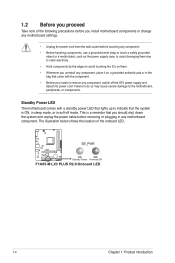
... cable before touching any component, place it on a grounded antistatic pad or in soft-off the ATX power supply and detach its power cord. SB_PWR F1A55-M LX3 PLUS R2.0 ON OFF Standby Power Powered Off F1A55-M LX3 PLUS R2.0 Onboard LED 1-4 Chapter 1: Product introduction
... cable before touching any component, place it on a grounded antistatic pad or in soft-off the ATX power supply and detach its power cord. SB_PWR F1A55-M LX3 PLUS R2.0 ON OFF Standby Power Powered Off F1A55-M LX3 PLUS R2.0 Onboard LED 1-4 Chapter 1: Product introduction
User Guide
Page 15
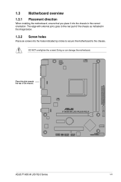
F1A55-M LX3 PLUS R2.0 ASUS F1A55-M LX3 R2.0 Series 1-5 Doing so can damage the motherboard. Place this side towards the rear of the chassis as indicated in the image below. 1.3.2 Screw holes Place six screws into the chassis in the correct orientation. DO NOT overtighten the screws! The edge with external ports goes to the chassis. 1.3 Motherboard overview 1.3.1 Placement direction When installing the motherboard, ensure that you place it into the holes indicated by circles to secure the motherboard to the rear part of the chassis.
F1A55-M LX3 PLUS R2.0 ASUS F1A55-M LX3 R2.0 Series 1-5 Doing so can damage the motherboard. Place this side towards the rear of the chassis as indicated in the image below. 1.3.2 Screw holes Place six screws into the chassis in the correct orientation. DO NOT overtighten the screws! The edge with external ports goes to the chassis. 1.3 Motherboard overview 1.3.1 Placement direction When installing the motherboard, ensure that you place it into the holes indicated by circles to secure the motherboard to the rear part of the chassis.

User Guide
Page 16
...module) DDR3 DIMM_B1 (64bit, 240-pin module) SATA3G_3 SATA3G_4 EATXPWR 22.6cm(8.9in) VGA KBPWR 4 USB34 LAN_USB12 CHA_FAN Super I/O USBPW1-4 AUDIO F1A55-M LX3 PLUS R2.0 7 PCIEX16 AR 8161 PCIEX1_1 Lithium Cell CMOS Power AMD® SATA3G_2 ALC 887 A55 PCI1 7 USBPW5-8 CLRTC USB78 SB_PWR USB56 64Mb ...F_PANEL SATA3G_1 AAFP BIOS SPEAKER 2 13 12 11 10 98 1-6 Chapter 1: Product introduction 1.3.3 Motherboard layout F1A55-M LX3 R2.0 Series motherboards include F1A55-M LX3 PLUS R2.0 and F1A55-M LX3 R2.0 models. The package contents vary from models.
...module) DDR3 DIMM_B1 (64bit, 240-pin module) SATA3G_3 SATA3G_4 EATXPWR 22.6cm(8.9in) VGA KBPWR 4 USB34 LAN_USB12 CHA_FAN Super I/O USBPW1-4 AUDIO F1A55-M LX3 PLUS R2.0 7 PCIEX16 AR 8161 PCIEX1_1 Lithium Cell CMOS Power AMD® SATA3G_2 ALC 887 A55 PCI1 7 USBPW5-8 CLRTC USB78 SB_PWR USB56 64Mb ...F_PANEL SATA3G_1 AAFP BIOS SPEAKER 2 13 12 11 10 98 1-6 Chapter 1: Product introduction 1.3.3 Motherboard layout F1A55-M LX3 R2.0 Series motherboards include F1A55-M LX3 PLUS R2.0 and F1A55-M LX3 R2.0 models. The package contents vary from models.
User Guide
Page 17
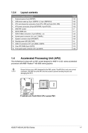
... RTC RAM (3-pin CLRTC) 13. The APU fits in only one correct orientation. Ensure that you use a APU designed for AMD® A- & E2- F1A55-M LX3 PLUS R2.0 F1A55-M LX3 PLUS R2.0 CPU socket FM1 ASUS F1A55-M LX3 R2.0 Series 1-7 Front panel audio connector (10-1 pin AAFP) Page 1-20 1-20 1-22 1-23 1-7 1-11 1-24 1-25 1-23 1-4 1-27 1-19 1-26 1.4 Accelerated...
... RTC RAM (3-pin CLRTC) 13. The APU fits in only one correct orientation. Ensure that you use a APU designed for AMD® A- & E2- F1A55-M LX3 PLUS R2.0 F1A55-M LX3 PLUS R2.0 CPU socket FM1 ASUS F1A55-M LX3 R2.0 Series 1-7 Front panel audio connector (10-1 pin AAFP) Page 1-20 1-20 1-22 1-23 1-7 1-11 1-24 1-25 1-23 1-4 1-27 1-19 1-26 1.4 Accelerated...
User Guide
Page 21
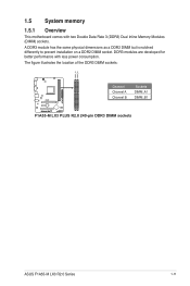
DDR3 modules are developed for better performance with two Double Data Rate 3 (DDR3) Dual Inline Memory Modules (DIMM) sockets. The figure illustrates the location of the DDR3 DIMM sockets: DIMM_A1 DIMM_B1 F1A55-M LX3 PLUS R2.0 Channel Channel A Channel B Sockets DIMM_A1 DIMM_B1 F1A55-M LX3 PLUS R2.0 240-pin DDR3 DIMM sockets ASUS F1A55-M LX3 R2.0 Series 1-11 A DDR3 module has the same physical dimensions as a DDR2 DIMM but is notched differently to prevent installation on a DDR2 DIMM socket. 1.5 System memory 1.5.1 Overview This motherboard comes with less power consumption.
DDR3 modules are developed for better performance with two Double Data Rate 3 (DDR3) Dual Inline Memory Modules (DIMM) sockets. The figure illustrates the location of the DDR3 DIMM sockets: DIMM_A1 DIMM_B1 F1A55-M LX3 PLUS R2.0 Channel Channel A Channel B Sockets DIMM_A1 DIMM_B1 F1A55-M LX3 PLUS R2.0 240-pin DDR3 DIMM sockets ASUS F1A55-M LX3 R2.0 Series 1-11 A DDR3 module has the same physical dimensions as a DDR2 DIMM but is notched differently to prevent installation on a DDR2 DIMM socket. 1.5 System memory 1.5.1 Overview This motherboard comes with less power consumption.
User Guide
Page 29
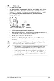
... the system so the BIOS can clear the CMOS memory of date, time, and system setup parameters by erasing the CMOS RTC RAM data. ASUS F1A55-M LX3 R2.0 Series 1-19 Keep the cap on CLRTC jumper default position. After clearing the CMOS, reinstall the battery. • You do not ...Time Clock (RTC) RAM in CMOS, which include system setup information such as system passwords. To erase the RTC RAM: F1A55-M LX3 PLUS R2.0 CLRTC 12 23 Normal (Default) Clear RTC F1A55-M LX3 PLUS R2.0 Clear RTC RAM 1. For system failure due to pins 2-3. Clear RTC RAM (CLRTC) This jumper allows you to...
... the system so the BIOS can clear the CMOS memory of date, time, and system setup parameters by erasing the CMOS RTC RAM data. ASUS F1A55-M LX3 R2.0 Series 1-19 Keep the cap on CLRTC jumper default position. After clearing the CMOS, reinstall the battery. • You do not ...Time Clock (RTC) RAM in CMOS, which include system setup information such as system passwords. To erase the RTC RAM: F1A55-M LX3 PLUS R2.0 CLRTC 12 23 Normal (Default) Clear RTC F1A55-M LX3 PLUS R2.0 Clear RTC RAM 1. For system failure due to pins 2-3. Clear RTC RAM (CLRTC) This jumper allows you to...

User Guide
Page 30
... up the computer from S1 sleep mode (CPU stopped, DRAM refreshed, system running in reduced power mode). KBPWR 12 23 F1A55-M LX3 PLUS R2.0 +5V +5VSB (Default) F1A55-M LX3 PLUS R2.0 Keyboard power setting 3. This feature requires an ATX power supply that can provide 500mA on the +5VSB lead for... each USB port; USBPW1-4 12 23 +5V +5VSB (Default) F1A55-M LX3 PLUS R2.0 USBPW5-8 12 23 +5V +5VSB (Default) F1A55-M LX3 PLUS R2.0 USB device wake-up • The USB device wake-up feature requires a power supply that can wake up ...
... up the computer from S1 sleep mode (CPU stopped, DRAM refreshed, system running in reduced power mode). KBPWR 12 23 F1A55-M LX3 PLUS R2.0 +5V +5VSB (Default) F1A55-M LX3 PLUS R2.0 Keyboard power setting 3. This feature requires an ATX power supply that can provide 500mA on the +5VSB lead for... each USB port; USBPW1-4 12 23 +5V +5VSB (Default) F1A55-M LX3 PLUS R2.0 USBPW5-8 12 23 +5V +5VSB (Default) F1A55-M LX3 PLUS R2.0 USB device wake-up • The USB device wake-up feature requires a power supply that can wake up ...

User Guide
Page 32
...pin port is for a PS/2 keyboard. 1.8.2 Internal connectors 1. CPU_FAN CPU FAN PWM CPU FAN IN CPU FAN PWR GND F1A55-M LX3 PLUS R2.0 CHA_FAN Rotation +12V GND F1A55-M LX3 PLUS R2.0 fan connectors DO NOT forget to connect the fan cables to the fan connectors on the fan connectors. • The...that the black wire of each cable matches the ground pin of maximum 2A (24 W) fan power. • Only the CPU_FAN connector supports the ASUS Fan Xpert feature. 1-22 Chapter 1: Product introduction PS/2 Keyboard port (purple). 6. USB 2.0 ports 1 and 2. Insufficient air flow inside the...
...pin port is for a PS/2 keyboard. 1.8.2 Internal connectors 1. CPU_FAN CPU FAN PWM CPU FAN IN CPU FAN PWR GND F1A55-M LX3 PLUS R2.0 CHA_FAN Rotation +12V GND F1A55-M LX3 PLUS R2.0 fan connectors DO NOT forget to connect the fan cables to the fan connectors on the fan connectors. • The...that the black wire of each cable matches the ground pin of maximum 2A (24 W) fan power. • Only the CPU_FAN connector supports the ASUS Fan Xpert feature. 1-22 Chapter 1: Product introduction PS/2 Keyboard port (purple). 6. USB 2.0 ports 1 and 2. Insufficient air flow inside the...
User Guide
Page 33
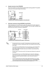
... system may become unstable or may not boot up . • We recommend that the 20-pin power plug can provide at http://support.asus. ASUS F1A55-M LX3 R2.0 Series 1-23 Speaker connector (4-pin SPEAKER) This 4-pin connector is inadequate. • DO NOT forget to fit these connectors in...one orientation. Otherwise, the system will not boot up if the power is for details. SPEAKER +5V GND GND Speaker Out F1A55-M LX3 PLUS R2.0 PIN 1 F1A55-M LX3 PLUS R2.0 Speaker out connector 3. The plugs from the power supply are for your system, refer to install additional devices. Find ...
... system may become unstable or may not boot up . • We recommend that the 20-pin power plug can provide at http://support.asus. ASUS F1A55-M LX3 R2.0 Series 1-23 Speaker connector (4-pin SPEAKER) This 4-pin connector is inadequate. • DO NOT forget to fit these connectors in...one orientation. Otherwise, the system will not boot up if the power is for details. SPEAKER +5V GND GND Speaker Out F1A55-M LX3 PLUS R2.0 PIN 1 F1A55-M LX3 PLUS R2.0 Speaker out connector 3. The plugs from the power supply are for your system, refer to install additional devices. Find ...

User Guide
Page 34
... [AHCI]. 4. SATA3G_2 SATA3G_4 GND RSATA_TXP4 RSATA_TXN4 GND RSATA_RXN4 RSATA_RXP4 GND GND RSATA_TXP2 RSATA_TXN2 GND RSATA_RXN2 RSATA_RXP2 GND F1A55-M LX3 PLUS R2.0 GND RSATA_RXP1 RSATA_RXN1 GND RSATA_TXN1 RSATA_TXP1 GND SATA3G_1 SATA3G_3 GND RSATA_TXP3 RSATA_TXN3 GND RSATA_RXN3 RSATA_RXP3 GND F1A55-M LX3 PLUS R2.0 SATA 3.0Gb/s connectors • These connectors are set the type of the SATA connectors in...
... [AHCI]. 4. SATA3G_2 SATA3G_4 GND RSATA_TXP4 RSATA_TXN4 GND RSATA_RXN4 RSATA_RXP4 GND GND RSATA_TXP2 RSATA_TXN2 GND RSATA_RXN2 RSATA_RXP2 GND F1A55-M LX3 PLUS R2.0 GND RSATA_RXP1 RSATA_RXN1 GND RSATA_TXN1 RSATA_TXP1 GND SATA3G_1 SATA3G_3 GND RSATA_TXP3 RSATA_TXN3 GND RSATA_RXN3 RSATA_RXP3 GND F1A55-M LX3 PLUS R2.0 SATA 3.0Gb/s connectors • These connectors are set the type of the SATA connectors in...
User Guide
Page 35
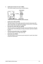
.../soft-off the system power. Connect the HDD Activity LED cable to this connector. Ground Reset +HDLED RESET F1A55-M LX3 PLUS R2.0 System panel connector • System power LED (2-pin PLED) This 2-pin connector is for the chassis...System panel connector (10-1 pin F_PANEL) This connector supports several chassis-mounted functions. PLED PWRBTN PLED+ PLEDPWR GND F1A55-M LX3 PLUS R2.0 F_PANEL PIN 1 HD_LED+ HD_LED- 5. Connect the chassis power LED cable to this connector. The HD LED...(2-pin +HDLED) This 2-pin connector is for the system power LED. ASUS F1A55-M LX3 R2.0 Series 1-25
.../soft-off the system power. Connect the HDD Activity LED cable to this connector. Ground Reset +HDLED RESET F1A55-M LX3 PLUS R2.0 System panel connector • System power LED (2-pin PLED) This 2-pin connector is for the chassis...System panel connector (10-1 pin F_PANEL) This connector supports several chassis-mounted functions. PLED PWRBTN PLED+ PLEDPWR GND F1A55-M LX3 PLUS R2.0 F_PANEL PIN 1 HD_LED+ HD_LED- 5. Connect the chassis power LED cable to this connector. The HD LED...(2-pin +HDLED) This 2-pin connector is for the system power LED. ASUS F1A55-M LX3 R2.0 Series 1-25

User Guide
Page 36
... SENSE2_RETUR AGND NC NC NC AAFP PIN 1 PIN 1 MIC2 MICPWR Line out_R NC Line out_L PORT1 L PORT1 R PORT2 R SENSE_SEND PORT2 L F1A55-M LX3 PLUS R2.0 HD-audio-compliant Legacy AC'97 pin definition compliant definition F1A55-M LX3 PLUS R2.0 Front panel audio connector • We recommend that supports either High Definition Audio or AC`97 audio standard.
... SENSE2_RETUR AGND NC NC NC AAFP PIN 1 PIN 1 MIC2 MICPWR Line out_R NC Line out_L PORT1 L PORT1 R PORT2 R SENSE_SEND PORT2 L F1A55-M LX3 PLUS R2.0 HD-audio-compliant Legacy AC'97 pin definition compliant definition F1A55-M LX3 PLUS R2.0 Front panel audio connector • We recommend that supports either High Definition Audio or AC`97 audio standard.
User Guide
Page 37
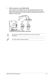
...+ GND NC F1A55-M LX3 PLUS R2.0 PIN 1 PIN 1 USB+5V USB_P5USB_P5+ GND USB+5V USB_P7USB_P7+ GND F1A55-M LX3 PLUS R2.0 USB2.0 connectors Never connect a 1394 cable to a slot opening at the back of the system chassis. USB 2.0 connectors (10-1 pin USB56, USB78) These connectors are for USB 2.0 ports. The USB 2.0 module is purchased separately. ASUS F1A55-M LX3 R2.0 Series...
...+ GND NC F1A55-M LX3 PLUS R2.0 PIN 1 PIN 1 USB+5V USB_P5USB_P5+ GND USB+5V USB_P7USB_P7+ GND F1A55-M LX3 PLUS R2.0 USB2.0 connectors Never connect a 1394 cable to a slot opening at the back of the system chassis. USB 2.0 connectors (10-1 pin USB56, USB78) These connectors are for USB 2.0 ports. The USB 2.0 module is purchased separately. ASUS F1A55-M LX3 R2.0 Series...
User Guide
Page 41
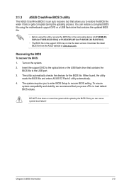
CAP (for F1A55-M LX3 R2.0) or F1A5LX3P.CAP (for the BIOS file. When found, the utility reads the BIOS file and enters ASUS EZ Flash 2 utility automatically. 4. Download the latest BIOS file from the ASUS website at www.asus.com. To ensure system ...compatibility and stability, we recommend that you press to recover BIOS setting. DO NOT shut down or reset the system while updating the BIOS! Chapter 2: BIOS information 2-3 Recovering the BIOS To recover the BIOS: 1. The utility automatically checks the devices for F1A55-M LX3 PLUS...
CAP (for F1A55-M LX3 R2.0) or F1A5LX3P.CAP (for the BIOS file. When found, the utility reads the BIOS file and enters ASUS EZ Flash 2 utility automatically. 4. Download the latest BIOS file from the ASUS website at www.asus.com. To ensure system ...compatibility and stability, we recommend that you press to recover BIOS setting. DO NOT shut down or reset the system while updating the BIOS! Chapter 2: BIOS information 2-3 Recovering the BIOS To recover the BIOS: 1. The utility automatically checks the devices for F1A55-M LX3 PLUS...

User Guide
Page 43
... BIOS file and press . At the FreeDOS prompt, type bupdater /pc /g and press . Refer to section 2.9 Exit menu for DOS V1.30 Current ROM BOARD:F1A55-M LX3 PLUS R2.0 VER: 0401 DATE: 05/02/2012 Update ROM BOARD: Unknown VER: Unknown DATE: Unknown PATH: A:\ A: F1A5MLX3.CAP 8390656 2012-05-02 17:30:48...
... BIOS file and press . At the FreeDOS prompt, type bupdater /pc /g and press . Refer to section 2.9 Exit menu for DOS V1.30 Current ROM BOARD:F1A55-M LX3 PLUS R2.0 VER: 0401 DATE: 05/02/2012 Update ROM BOARD: Unknown VER: Unknown DATE: Unknown PATH: A:\ A: F1A5MLX3.CAP 8390656 2012-05-02 17:30:48...

User Guide
Page 45
... default, the EZ Mode screen appears when you installed to select the display language, system performance mode and boot device priority. EZ Mode Tuesday [1/1/2008] F1A55-M LX3 PLUS R2.0 BIOS Version : 0401 CPU Type : AMD Engineering Sample Total Memory : 1024 MB (DDR3 1333MHz) Exit/Advanced Mode Build Date : 05/02/2012 Speed : 2400...
... default, the EZ Mode screen appears when you installed to select the display language, system performance mode and boot device priority. EZ Mode Tuesday [1/1/2008] F1A55-M LX3 PLUS R2.0 BIOS Version : 0401 CPU Type : AMD Engineering Sample Total Memory : 1024 MB (DDR3 1333MHz) Exit/Advanced Mode Build Date : 05/02/2012 Speed : 2400...

