User Manual
Page 1
Motherboard F1A55-M LX Series • F1A55-M LX • F1A55-M LX PLUS
Motherboard F1A55-M LX Series • F1A55-M LX • F1A55-M LX PLUS
User Manual
Page 8
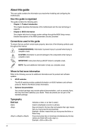
...have been added by your dealer. These documents are not part of the BIOS parameters are linked with a plus sign (+). Used to the ASUS contact information. 2. About this guide To ensure that may include optional documentation, such as warranty flyers, that you ...complete a task. ASUS websites The ASUS website provides updated information on ASUS hardware and software products. How this manual. IMPORTANT: Instructions that you must press two or more information ...
...have been added by your dealer. These documents are not part of the BIOS parameters are linked with a plus sign (+). Used to the ASUS contact information. 2. About this guide To ensure that may include optional documentation, such as warranty flyers, that you ...complete a task. ASUS websites The ASUS website provides updated information on ASUS hardware and software products. How this manual. IMPORTANT: Instructions that you must press two or more information ...
User Manual
Page 10
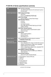
Protect 3.0 (F1A55-M LX PLUS only) ASUS Power Design - Industry leading 4+1 Phase Power Design ASUS Exclusive Features - ASUS MyLogo 2™ 100% All high-quality conductive polymer conductors (F1A55-M LX PLUS only) Precision Tweaker 2 - APU frequency tuning from 90MHz up to 300MHz at 0.003125V increment - ASUS Fanless Design: Stylish heatsink solution - ASUS Fan Xpert ASUS EZ DIY - vCore: Adjustable CPU voltage at 1MHz increment Overclocking...
Protect 3.0 (F1A55-M LX PLUS only) ASUS Power Design - Industry leading 4+1 Phase Power Design ASUS Exclusive Features - ASUS MyLogo 2™ 100% All high-quality conductive polymer conductors (F1A55-M LX PLUS only) Precision Tweaker 2 - APU frequency tuning from 90MHz up to 300MHz at 0.003125V increment - ASUS Fanless Design: Stylish heatsink solution - ASUS Fan Xpert ASUS EZ DIY - vCore: Adjustable CPU voltage at 1MHz increment Overclocking...
User Manual
Page 13
... supports AMD® A- & E2- Before you for the following items. Motherboard Cables Accessories Application DVD Documentations ASUS F1A55-M LX Series motherboard 2 x Serial ATA 3.0Gb/s cables 1 x I/O shield ASUS motherboard Support DVD User Manual • F1A55-M LX Series motherboards include F1A55-M LX PLUS and F1A55-M LX two models. This revolutionary APU (Accelerated Processing Unit) combines processing power and advanced DirectX 11 graphics in...
... supports AMD® A- & E2- Before you for the following items. Motherboard Cables Accessories Application DVD Documentations ASUS F1A55-M LX Series motherboard 2 x Serial ATA 3.0Gb/s cables 1 x I/O shield ASUS motherboard Support DVD User Manual • F1A55-M LX Series motherboards include F1A55-M LX PLUS and F1A55-M LX two models. This revolutionary APU (Accelerated Processing Unit) combines processing power and advanced DirectX 11 graphics in...
User Manual
Page 14
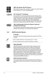
... CrossFireX™ allows higher antialiasing, anisotropic filtering, shading, and texture settings. Adjust your USB device's conditions. ASUS Anti-Surge Protection This special design protects expensive devices and the motherboard from damage caused by the F12 hotkey BIOS ...Control Center. 100% All High-quality Conductive Polymer Capacitors (F1A55-M LX PLUS only) This motherboard uses all high-quality conductive polymer capacitors for durability, improved lifespan, and enhanced thermal capacity. 1.3.2 ASUS Exclusive Features Ai Charger Ai Charger is for experienced performance ...
... CrossFireX™ allows higher antialiasing, anisotropic filtering, shading, and texture settings. Adjust your USB device's conditions. ASUS Anti-Surge Protection This special design protects expensive devices and the motherboard from damage caused by the F12 hotkey BIOS ...Control Center. 100% All High-quality Conductive Polymer Capacitors (F1A55-M LX PLUS only) This motherboard uses all high-quality conductive polymer capacitors for durability, improved lifespan, and enhanced thermal capacity. 1.3.2 ASUS Exclusive Features Ai Charger Ai Charger is for experienced performance ...
User Manual
Page 16
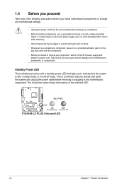
The illustration below shows the location of the following precautions before you install or remove any motherboard component. F1A55-M LX PLUS SB_PWR ON OFF Standby Power Powered Off F1A55-M LX PLUS Onboard LED 1-4 Chapter 1: Product introduction Standby Power LED The motherboard comes with a standby power LED that lights up to indicate that the system is a reminder ...
The illustration below shows the location of the following precautions before you install or remove any motherboard component. F1A55-M LX PLUS SB_PWR ON OFF Standby Power Powered Off F1A55-M LX PLUS Onboard LED 1-4 Chapter 1: Product introduction Standby Power LED The motherboard comes with a standby power LED that lights up to indicate that the system is a reminder ...
User Manual
Page 17
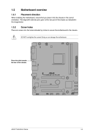
F1A55-M LX PLUS ASUS F1A55-M LX Series 1-5 Place this side towards the rear of the chassis as indicated in the image below. 1.5.2 Screw holes Place six screws into the chassis in the correct orientation. Doing so can damage the motherboard. 1.5 Motherboard overview 1.5.1 Placement direction When installing the motherboard, ensure that you place it into the holes indicated by circles to secure the motherboard to the rear part of the chassis. The edge with external ports goes to the chassis. DO NOT overtighten the screws!
F1A55-M LX PLUS ASUS F1A55-M LX Series 1-5 Place this side towards the rear of the chassis as indicated in the image below. 1.5.2 Screw holes Place six screws into the chassis in the correct orientation. Doing so can damage the motherboard. 1.5 Motherboard overview 1.5.1 Placement direction When installing the motherboard, ensure that you place it into the holes indicated by circles to secure the motherboard to the rear part of the chassis. The edge with external ports goes to the chassis. DO NOT overtighten the screws!
User Manual
Page 18
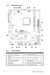
...-pin module) DDR3 DIMM_B1 (64bit, 240-pin module) EATXPWR SATA3G_5 SATA3G_6 24.4cm(9.6in) LPT VGA 3 USB34 USBPW1-6 LAN1_USB12 AUDIO 14 RTL 8111E Super I/O CHA_FAN F1A55-M LX PLUS PCIEX16_1 PCIEX1_1 CLRTC PCI1 Lithium Cell CMOS Power 7 SB_PWR SATA3G_4 8 AMD® A55 SATA3G_3 SATA3G_2 7 ALC 887 AAFP PCIEX16_2 USBPW7-12 USB1112 SPDIF_OUT USB910 USB78...
...-pin module) DDR3 DIMM_B1 (64bit, 240-pin module) EATXPWR SATA3G_5 SATA3G_6 24.4cm(9.6in) LPT VGA 3 USB34 USBPW1-6 LAN1_USB12 AUDIO 14 RTL 8111E Super I/O CHA_FAN F1A55-M LX PLUS PCIEX16_1 PCIEX1_1 CLRTC PCI1 Lithium Cell CMOS Power 7 SB_PWR SATA3G_4 8 AMD® A55 SATA3G_3 SATA3G_2 7 ALC 887 AAFP PCIEX16_2 USBPW7-12 USB1112 SPDIF_OUT USB910 USB78...
User Manual
Page 19
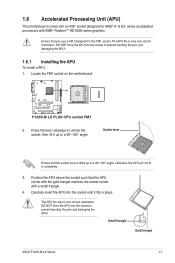
F1A55-M LX PLUS F1A55-M LX PLUS CPU socket FM1 2. Position the APU above the socket such that you use a APU designed for AMD® A- & E2- Carefully insert the APU into the ...! series accelerated processors with a small triangle. 4. Locate the FM1 socket on the motherboard. otherwise, the APU will not fit in place. Small triangle Gold triangle ASUS F1A55-M LX Series 1-7 Press the lever sideways to a 90°-100° angle. Socket lever Ensure that the socket lever is lifted up to unlock the socket...
F1A55-M LX PLUS F1A55-M LX PLUS CPU socket FM1 2. Position the APU above the socket such that you use a APU designed for AMD® A- & E2- Carefully insert the APU into the ...! series accelerated processors with a small triangle. 4. Locate the FM1 socket on the motherboard. otherwise, the APU will not fit in place. Small triangle Gold triangle ASUS F1A55-M LX Series 1-7 Press the lever sideways to a 90°-100° angle. Socket lever Ensure that the socket lever is lifted up to unlock the socket...
User Manual
Page 20
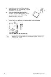
When the APU is locked. 6. CPU_FAN F1A55-M LX PLUS F1A55-M LX PLUS CPU fan connector DO NOT forget to plug this connector. Hardware monitoring errors can also refer to section 1.6.2 Installing heatsink and fan for instructions. 7. Install a ...
When the APU is locked. 6. CPU_FAN F1A55-M LX PLUS F1A55-M LX PLUS CPU fan connector DO NOT forget to plug this connector. Hardware monitoring errors can also refer to section 1.6.2 Installing heatsink and fan for instructions. 7. Install a ...
User Manual
Page 22
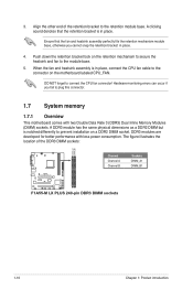
.... 5. Push down the retention bracket lock on the motherboard labeled CPU_FAN. Align the other end of the DDR3 DIMM sockets: DIMM_A1 DIMM_B1 F1A55-M LX PLUS Channel Channel A Channel B Sockets DIMM_A1 DIMM_B1 F1A55-M LX PLUS 240-pin DDR3 DIMM sockets 1-10 Chapter 1: Product introduction DO NOT forget to plug this connector. 1.7 System memory 1.7.1 Overview This motherboard comes...
.... 5. Push down the retention bracket lock on the motherboard labeled CPU_FAN. Align the other end of the DDR3 DIMM sockets: DIMM_A1 DIMM_B1 F1A55-M LX PLUS Channel Channel A Channel B Sockets DIMM_A1 DIMM_B1 F1A55-M LX PLUS 240-pin DDR3 DIMM sockets 1-10 Chapter 1: Product introduction DO NOT forget to plug this connector. 1.7 System memory 1.7.1 Overview This motherboard comes...
User Manual
Page 30
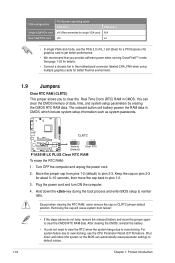
The onboard button cell battery powers the RAM data in CMOS. F1A55-M LX PLUS CLRTC 12 23 Normal (Default) Clear RTC F1A55-M LX PLUS Clear RTC RAM To erase the RTC RAM: 1. Move the jumper cap from pins 1-2 (default) to overclocking, use the PCIe 2.0 x16_1 slot (blue) for a PCI ...
The onboard button cell battery powers the RAM data in CMOS. F1A55-M LX PLUS CLRTC 12 23 Normal (Default) Clear RTC F1A55-M LX PLUS Clear RTC RAM To erase the RTC RAM: 1. Move the jumper cap from pins 1-2 (default) to overclocking, use the PCIe 2.0 x16_1 slot (blue) for a PCI ...
User Manual
Page 31
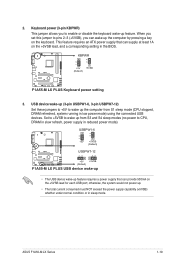
... system running in reduced power mode). This feature requires an ATX power supply that can provide 500mA on the +5VSB lead for each USB port; ASUS F1A55-M LX Series 1-19 2. Set to +5VSB to wake up from S3 and S4 sleep modes (no power to wake up . • The total ...pressing a key on the +5VSB lead, and a corresponding setting in sleep mode. USBPW1-6 12 23 +5V +5VSB (Default) F1A55-M LX PLUS USBPW7-12 12 23 +5V +5VSB (Default) F1A55-M LX PLUS USB device wake-up • The USB device wake-up feature requires a power supply that can wake up feature. When you can...
... system running in reduced power mode). This feature requires an ATX power supply that can provide 500mA on the +5VSB lead for each USB port; ASUS F1A55-M LX Series 1-19 2. Set to +5VSB to wake up from S3 and S4 sleep modes (no power to wake up . • The total ...pressing a key on the +5VSB lead, and a corresponding setting in sleep mode. USBPW1-6 12 23 +5V +5VSB (Default) F1A55-M LX PLUS USBPW7-12 12 23 +5V +5VSB (Default) F1A55-M LX PLUS USB device wake-up • The USB device wake-up feature requires a power supply that can wake up feature. When you can...
User Manual
Page 33
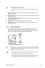
... two 4-pin Universal Serial Bus (USB) ports are for USB 2.0/1.1 devices. 1.10.2 Internal connectors 1. USB 2.0 ports 5 and 6. ASUS F1A55-M LX Series 1-21 COM port. This port is for a VGA monitor or other serial devices. 11. Insufficient air flow inside the system may ... two 4-pin Universal Serial Bus (USB) ports are not jumpers! CPU_FAN CPU FAN PWM CPU FAN IN CPU FAN PWR GND F1A55-M LX PLUS CHA_FAN GND +12V Rotation F1A55-M LX PLUS fan connectors DO NOT forget to connect the fan cables to the fan connectors on the fan connectors. • The CPU_FAN connector...
... two 4-pin Universal Serial Bus (USB) ports are for USB 2.0/1.1 devices. 1.10.2 Internal connectors 1. USB 2.0 ports 5 and 6. ASUS F1A55-M LX Series 1-21 COM port. This port is for a VGA monitor or other serial devices. 11. Insufficient air flow inside the system may ... two 4-pin Universal Serial Bus (USB) ports are not jumpers! CPU_FAN CPU FAN PWM CPU FAN IN CPU FAN PWR GND F1A55-M LX PLUS CHA_FAN GND +12V Rotation F1A55-M LX PLUS fan connectors DO NOT forget to connect the fan cables to the fan connectors on the fan connectors. • The CPU_FAN connector...
User Manual
Page 34
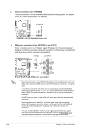
... system may become unstable or may not boot up . • We recommend that the 20-pin power plug can provide at http://support.asus. Find the proper orientation and push down firmly until the connectors completely fit. This PSU type has 24-pin and 4-pin power plugs. ...plug. The plugs from the power supply are for your system, refer to hear system beeps and warnings. +5V GND GND Speaker Out SPEAKER F1A55-M LX PLUS PIN 1 F1A55-M LX PLUS Speaker connector 3. ATX power connectors (24-pin EATXPWR, 4-pin ATX12V) These connectors are designed to use a PSU with higher power output ...
... system may become unstable or may not boot up . • We recommend that the 20-pin power plug can provide at http://support.asus. Find the proper orientation and push down firmly until the connectors completely fit. This PSU type has 24-pin and 4-pin power plugs. ...plug. The plugs from the power supply are for your system, refer to hear system beeps and warnings. +5V GND GND Speaker Out SPEAKER F1A55-M LX PLUS PIN 1 F1A55-M LX PLUS Speaker connector 3. ATX power connectors (24-pin EATXPWR, 4-pin ATX12V) These connectors are designed to use a PSU with higher power output ...
User Manual
Page 35
...RSATA_RXN5 RSATA_RXP5 GND GND RSATA_TXP3 RSATA_TXN3 GND RSATA_RXN3 RSATA_RXP3 GND SATA3G_2 GND RSATA_TXP2 RSATA_TXN2 GND RSATA_RXN2 RSATA_RXP2 GND F1A55-M LX PLUS SATA3G_1 GND RSATA_TXP1 RSATA_TXN1 GND RSATA_RXN1 RSATA_RXP1 GND F1A55-M LX PLUS SATA 3.0Gb/s connectors • These connectors are set to [RAID]. The Serial ATA RAID ... connectors in the BIOS to these connectors, set the type of the SATA connectors in the BIOS to IDE mode by default. ASUS F1A55-M LX Series 1-23 If you installed Serial ATA hard disk drives, you can create a RAID 0, RAID 1, RAID 10, or JBOD...
...RSATA_RXN5 RSATA_RXP5 GND GND RSATA_TXP3 RSATA_TXN3 GND RSATA_RXN3 RSATA_RXP3 GND SATA3G_2 GND RSATA_TXP2 RSATA_TXN2 GND RSATA_RXN2 RSATA_RXP2 GND F1A55-M LX PLUS SATA3G_1 GND RSATA_TXP1 RSATA_TXN1 GND RSATA_RXN1 RSATA_RXP1 GND F1A55-M LX PLUS SATA 3.0Gb/s connectors • These connectors are set to [RAID]. The Serial ATA RAID ... connectors in the BIOS to these connectors, set the type of the SATA connectors in the BIOS to IDE mode by default. ASUS F1A55-M LX Series 1-23 If you installed Serial ATA hard disk drives, you can create a RAID 0, RAID 1, RAID 10, or JBOD...
User Manual
Page 36
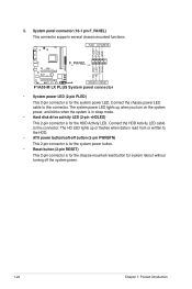
...the system power button. • Reset button (2-pin RESET) This 2-pin connector is for the system power LED. PLED PWRBTN PLED+ PLEDPWR GND F1A55-M LX PLUS F_PANEL PIN 1 HD_LED+ HD_LED- The system power LED lights up or flashes when data is read from or written to the HDD. • ...ATX power button/soft-off the system power. 1-24 Chapter 1: Product introduction Ground Reset +HDLED RESET F1A55-M LX PLUS System panel connector • System power LED (2-pin PLED) This 2-pin connector is for the HDD Activity LED. Connect the HDD Activity LED cable...
...the system power button. • Reset button (2-pin RESET) This 2-pin connector is for the system power LED. PLED PWRBTN PLED+ PLEDPWR GND F1A55-M LX PLUS F_PANEL PIN 1 HD_LED+ HD_LED- The system power LED lights up or flashes when data is read from or written to the HDD. • ...ATX power button/soft-off the system power. 1-24 Chapter 1: Product introduction Ground Reset +HDLED RESET F1A55-M LX PLUS System panel connector • System power LED (2-pin PLED) This 2-pin connector is for the HDD Activity LED. Connect the HDD Activity LED cable...
User Manual
Page 37
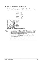
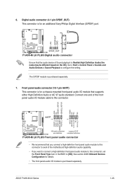
Go to Start > Control Panel > Sounds and Audio Devices > Sound Playback to this connector. ASUS F1A55-M LX Series 1-25 Front panel audio connector (10-1 pin AAFP) This connector is for a chassis-mounted front panel audio I /O module ...playback is purchased separately. See section 2.5.5 Onboard Devices Configuration for an additional Sony/Philips Digital Interface (S/PDIF) port. +5V SPDIFOUT GND F1A55-M LX PLUS SPDIF_OUT F1A55-M LX PLUS Digital audio connector Ensure that you connect a high-definition front panel audio module to this connector to avail of the front panel audio ...
Go to Start > Control Panel > Sounds and Audio Devices > Sound Playback to this connector. ASUS F1A55-M LX Series 1-25 Front panel audio connector (10-1 pin AAFP) This connector is for a chassis-mounted front panel audio I /O module ...playback is purchased separately. See section 2.5.5 Onboard Devices Configuration for an additional Sony/Philips Digital Interface (S/PDIF) port. +5V SPDIFOUT GND F1A55-M LX PLUS SPDIF_OUT F1A55-M LX PLUS Digital audio connector Ensure that you connect a high-definition front panel audio module to this connector to avail of the front panel audio ...
User Manual
Page 38
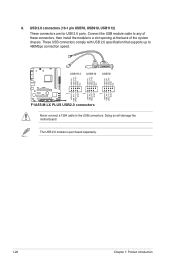
... USB1112 USB910 USB78 USB+5V USB_P12USB_P12+ GND NC USB+5V USB_P10USB_P10+ GND NC USB+5V USB_P8USB_P8+ GND NC F1A55-M LX PLUS PIN 1 PIN 1 PIN 1 USB+5V USB_P11USB_P11+ GND USB+5V USB_P9USB_P9+ GND USB+5V USB_P7USB_P7+ GND F1A55-M LX PLUS USB2.0 connectors Never connect a 1394 cable to 480Mbps connection speed. Connect the USB module cable to any...
... USB1112 USB910 USB78 USB+5V USB_P12USB_P12+ GND NC USB+5V USB_P10USB_P10+ GND NC USB+5V USB_P8USB_P8+ GND NC F1A55-M LX PLUS PIN 1 PIN 1 PIN 1 USB+5V USB_P11USB_P11+ GND USB+5V USB_P9USB_P9+ GND USB+5V USB_P7USB_P7+ GND F1A55-M LX PLUS USB2.0 connectors Never connect a 1394 cable to 480Mbps connection speed. Connect the USB module cable to any...
User Manual
Page 42
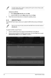
... latest BIOS file from a BIOS file a. ASUS EZ Flash 2 Utility V01.02 Flash Info MODEL: F1A55-M LX PLUS File Path: fs0:\ Drive fs0:\ VER: 0202 Folder Info 08/03/11 02:27p 4194304 Exit DATE: 08/03/2011 F1A55MLP.ROM File Info MODEL: F1A55-M LX PLUS Help Info VER: 0202 DATE: 08/03/...11 [Enter] Select or Load [Tab] Switch [Up/Down/PageUp/PageDown/Home/End] Move [Esc] Exit [F2] Backup 2-2 ASUS F1A55-M LX Series b. To update the BIOS using an OS‑based utility...
... latest BIOS file from a BIOS file a. ASUS EZ Flash 2 Utility V01.02 Flash Info MODEL: F1A55-M LX PLUS File Path: fs0:\ Drive fs0:\ VER: 0202 Folder Info 08/03/11 02:27p 4194304 Exit DATE: 08/03/2011 F1A55MLP.ROM File Info MODEL: F1A55-M LX PLUS Help Info VER: 0202 DATE: 08/03/...11 [Enter] Select or Load [Tab] Switch [Up/Down/PageUp/PageDown/Home/End] Move [Esc] Exit [F2] Backup 2-2 ASUS F1A55-M LX Series b. To update the BIOS using an OS‑based utility...


