
F1A55-M LK R2.0 User's Manual
Page 1
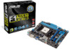
Motherboard F1A55-M LK R2.0
Motherboard F1A55-M LK R2.0
F1A55-M LK R2.0 User's Manual
Page 3
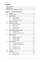
Contents Safety information vi About this guide vi F1A55-M LK R2.0 specifications summary viii Chapter 1: Product introduction 1.1 Welcome 1-1 1.2 Package contents 1-1 1.3 Special features 1-1 1.3.1 Product highlights 1-1 1.3.2 ASUS DIGI+ VRM 1-2 1.3.3 ASUS Exclusive Features 1-3 1.4 Before you proceed 1-5 1.5 Motherboard overview 1-6 1.5.1 Placement direction 1-6 1.5.2 Screw holes 1-6 1.5.3 Motherboard layout 1-7 1.5.4 Layout contents 1-7 1.6 Accelerated Processing Unit (APU 1-8 1.6.1 Installing the APU 1-8 1.6.2 Installing the heatsink and fan 1-10 1.7 System memory...
Contents Safety information vi About this guide vi F1A55-M LK R2.0 specifications summary viii Chapter 1: Product introduction 1.1 Welcome 1-1 1.2 Package contents 1-1 1.3 Special features 1-1 1.3.1 Product highlights 1-1 1.3.2 ASUS DIGI+ VRM 1-2 1.3.3 ASUS Exclusive Features 1-3 1.4 Before you proceed 1-5 1.5 Motherboard overview 1-6 1.5.1 Placement direction 1-6 1.5.2 Screw holes 1-6 1.5.3 Motherboard layout 1-7 1.5.4 Layout contents 1-7 1.6 Accelerated Processing Unit (APU 1-8 1.6.1 Installing the APU 1-8 1.6.2 Installing the heatsink and fan 1-10 1.7 System memory...
F1A55-M LK R2.0 User's Manual
Page 6
...the signal cables are not sure about the voltage of the electrical outlet you need when installing and configuring the motherboard. Operation safety • Before installing the motherboard and adding devices on a stable surface. • If you add a device. • Before connecting ...or removing signal cables from the motherboard, ensure that came with the product, contact a qualified service technician or your retailer. Detailed descriptions of the motherboard and the new technology it , carefully read all the manuals that all cables ...
...the signal cables are not sure about the voltage of the electrical outlet you need when installing and configuring the motherboard. Operation safety • Before installing the motherboard and adding devices on a stable surface. • If you add a device. • Before connecting ...or removing signal cables from the motherboard, ensure that came with the product, contact a qualified service technician or your retailer. Detailed descriptions of the motherboard and the new technology it , carefully read all the manuals that all cables ...
F1A55-M LK R2.0 User's Manual
Page 11
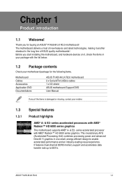
Before you for the following items. Motherboard Cables Accessories Application DVD Documentations ASUS F1A55-M LK R2.0 motherboard 2 x Serial ATA 3.0Gb/s cables 1 x I/O shield ASUS motherboard Support DVD User Manual If any of ASUS quality motherboards! Thank you start installing the motherboard, and hardware devices on it another standout in one small, energy-efficient design to 5GT/s. series accelerated processor with AMD® Radeon...
Before you for the following items. Motherboard Cables Accessories Application DVD Documentations ASUS F1A55-M LK R2.0 motherboard 2 x Serial ATA 3.0Gb/s cables 1 x I/O shield ASUS motherboard Support DVD User Manual If any of ASUS quality motherboards! Thank you start installing the motherboard, and hardware devices on it another standout in one small, energy-efficient design to 5GT/s. series accelerated processor with AMD® Radeon...
F1A55-M LK R2.0 User's Manual
Page 12
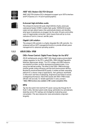
... carefully developed automated modes, or by automatically detecting current PC loadings and intelligently moderating power consumption. Boosted by world-renowned ASUS quality, it creates an ideal computing platform for the CPU, called DIGI+ VRM (Voltage Regulation Modules) digital power design...Engineered and tested to assure unmitigated performance, ASUS A55 boards with an ACPI management function to provide efficient power management for advanced operating systems. ASUS DIGI+ VRM DIGI+ Power Control: Digital Power Design for the APU* ASUS motherboards using user-defined profiles. It is a ...
... carefully developed automated modes, or by automatically detecting current PC loadings and intelligently moderating power consumption. Boosted by world-renowned ASUS quality, it creates an ideal computing platform for the CPU, called DIGI+ VRM (Voltage Regulation Modules) digital power design...Engineered and tested to assure unmitigated performance, ASUS A55 boards with an ACPI management function to provide efficient power management for advanced operating systems. ASUS DIGI+ VRM DIGI+ Power Control: Digital Power Design for the APU* ASUS motherboards using user-defined profiles. It is a ...
F1A55-M LK R2.0 User's Manual
Page 13
...you can prioritize your favorite software easily by power surges from damage caused by configuring profiles through the intutive user interface. ASUS F1A55-M LK R2.0 1-3 Advanced Mode for performance enthusiasts includes detailed DRAM settings via a dedicated memory info page for accessing memory information,.... The Network iControl feature does not support Windows® XP/Vista operating systems. ASUS Anti-Surge Protection This special design prevents expensive devices and the motherboard from switching power supply (PSU). Within the profile, programs can choose system performance ...
...you can prioritize your favorite software easily by power surges from damage caused by configuring profiles through the intutive user interface. ASUS F1A55-M LK R2.0 1-3 Advanced Mode for performance enthusiasts includes detailed DRAM settings via a dedicated memory info page for accessing memory information,.... The Network iControl feature does not support Windows® XP/Vista operating systems. ASUS Anti-Surge Protection This special design prevents expensive devices and the motherboard from switching power supply (PSU). Within the profile, programs can choose system performance ...
F1A55-M LK R2.0 User's Manual
Page 14
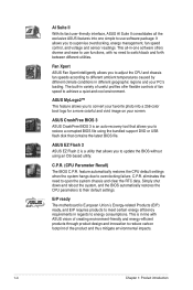
...your favorite photo into one software offers diverse and ease to use software package. ASUS CrashFree BIOS 3 ASUS CrashFree BIOS 3 is a utility that contains the latest BIOS file. ErP ready The motherboard is in regards to their default settings. AI Suite II With its fast ...user-friendly interface, ASUS AI Suite II consolidates all -in-one simple to use functions, with ASUS vision of creating environment-friendly and energy-efficient ...
...your favorite photo into one software offers diverse and ease to use software package. ASUS CrashFree BIOS 3 ASUS CrashFree BIOS 3 is a utility that contains the latest BIOS file. ErP ready The motherboard is in regards to their default settings. AI Suite II With its fast ...user-friendly interface, ASUS AI Suite II consolidates all -in-one simple to use functions, with ASUS vision of creating environment-friendly and energy-efficient ...
F1A55-M LK R2.0 User's Manual
Page 15
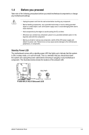
...-off the ATX power supply and detach its power cord. Standby Power LED The motherboard comes with the component. • Before you install or remove any motherboard settings. • Unplug the power cord from the wall socket before removing or ... antistatic pad or in any motherboard component. The illustration below shows the location of the following precautions before you install motherboard components or change any component, switch off mode. SB_PWR F1A55-M LK R2.0 ON OFF Standby Power Powered Off F1A55-M LK R2.0 Onboard LED ASUS F1A55-M LK R2.0 1-5 1.4 Before you proceed...
...-off the ATX power supply and detach its power cord. Standby Power LED The motherboard comes with the component. • Before you install or remove any motherboard settings. • Unplug the power cord from the wall socket before removing or ... antistatic pad or in any motherboard component. The illustration below shows the location of the following precautions before you install motherboard components or change any component, switch off mode. SB_PWR F1A55-M LK R2.0 ON OFF Standby Power Powered Off F1A55-M LK R2.0 Onboard LED ASUS F1A55-M LK R2.0 1-5 1.4 Before you proceed...
F1A55-M LK R2.0 User's Manual
Page 16
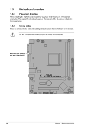
F1A55-M LK R2.0 1-6 Chapter 1: Product introduction Place this side towards the rear of the chassis as indicated in the correct orientation. 1.5 Motherboard overview 1.5.1 Placement direction When installing the motherboard, ensure that you place it into the chassis in the image below. 1.5.2 Screw holes Place six screws into the holes indicated by circles to secure the motherboard to the rear part of the chassis. DO NOT overtighten the screws! Doing so can damage the motherboard. The edge with external ports goes to the chassis.
F1A55-M LK R2.0 1-6 Chapter 1: Product introduction Place this side towards the rear of the chassis as indicated in the correct orientation. 1.5 Motherboard overview 1.5.1 Placement direction When installing the motherboard, ensure that you place it into the chassis in the image below. 1.5.2 Screw holes Place six screws into the holes indicated by circles to secure the motherboard to the rear part of the chassis. DO NOT overtighten the screws! Doing so can damage the motherboard. The edge with external ports goes to the chassis.
F1A55-M LK R2.0 User's Manual
Page 17
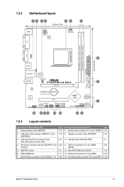
... SATA3G_1~4) Page Connectors/Jumpers/Slots/LED 1-19 8. Front panel audio connector (10-1 pin AAFP) Page 1-24 1-22 1-5 1-26 1-18 1-25 1-25 ASUS F1A55-M LK R2.0 1-7 Serial port connector (10-1 pin COM1) 1-23 14. 1.5.3 Motherboard layout 12 34 53 6 18.6cm(7.3in) KBMS ATX12V EPU CPU_FAN DVI SOCKET FM1 DDR3 DIMM_A1 (64bit, 240-pin module) DDR3...
... SATA3G_1~4) Page Connectors/Jumpers/Slots/LED 1-19 8. Front panel audio connector (10-1 pin AAFP) Page 1-24 1-22 1-5 1-26 1-18 1-25 1-25 ASUS F1A55-M LK R2.0 1-7 Serial port connector (10-1 pin COM1) 1-23 14. 1.5.3 Motherboard layout 12 34 53 6 18.6cm(7.3in) KBMS ATX12V EPU CPU_FAN DVI SOCKET FM1 DDR3 DIMM_A1 (64bit, 240-pin module) DDR3...
F1A55-M LK R2.0 User's Manual
Page 18
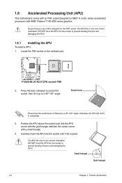
...8482; HD 6000 series graphics. The APU fits only in completely. 3. F1A55-M LK R2.0 F1A55-M LK R2.0 CPU socket FM1 2. Socket lever Ensure that you use a APU designed for AMD® A- & E2- 1.6 Accelerated Processing Unit (APU) This motherboard comes with an FM1 socket designed for the FM1 socket. DO NOT force ...APU To install a APU: 1. otherwise, the APU will not fit in one correct orientation. Locate the FM1 socket on the motherboard. Ensure that the socket lever is lifted up to a 90°-100° angle; series accelerated processors with a small triangle. 4.
...8482; HD 6000 series graphics. The APU fits only in completely. 3. F1A55-M LK R2.0 F1A55-M LK R2.0 CPU socket FM1 2. Socket lever Ensure that you use a APU designed for AMD® A- & E2- 1.6 Accelerated Processing Unit (APU) This motherboard comes with an FM1 socket designed for the FM1 socket. DO NOT force ...APU To install a APU: 1. otherwise, the APU will not fit in one correct orientation. Locate the FM1 socket on the motherboard. Ensure that the socket lever is lifted up to a 90°-100° angle; series accelerated processors with a small triangle. 4.
F1A55-M LK R2.0 User's Manual
Page 19
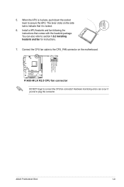
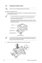
...ASUS F1A55-M LK R2.0 1-9 Install a APU heatsink and fan following the instructions that it is in place, push down the socket lever to secure the APU. Connect the CPU fan cable to the CPU_FAN connector on the side tab to plug this connector. The lever clicks on the motherboard.... You can occur if you fail to indicate that comes with the heatsink package. Hardware monitoring errors can also refer to connect the CPU fan connector! CPU_FAN F1A55-M LK R2.0 F1A55-M LK R2.0 CPU fan connector DO NOT forget to ...
...ASUS F1A55-M LK R2.0 1-9 Install a APU heatsink and fan following the instructions that it is in place, push down the socket lever to secure the APU. Connect the CPU fan cable to the CPU_FAN connector on the side tab to plug this connector. The lever clicks on the motherboard.... You can occur if you fail to indicate that comes with the heatsink package. Hardware monitoring errors can also refer to connect the CPU fan connector! CPU_FAN F1A55-M LK R2.0 F1A55-M LK R2.0 CPU fan connector DO NOT forget to ...
F1A55-M LK R2.0 User's Manual
Page 20
Attach one end of the installed CPU, ensuring that the heatsink fits properly on the motherboard upon purchase. • You do not match the CPU documentation, follow the latter. 2. Place the heatsink on top of the retention bracket to the CPU ... and fan assembly. If the instructions in this section do not have to remove the retention module base when installing the CPU or installing other motherboard components. • If you purchased a separate CPU heatsink and fan assembly, ensure that a Thermal Interface Material is already installed on the retention module base. •...
Attach one end of the installed CPU, ensuring that the heatsink fits properly on the motherboard upon purchase. • You do not match the CPU documentation, follow the latter. 2. Place the heatsink on top of the retention bracket to the CPU ... and fan assembly. If the instructions in this section do not have to remove the retention module base when installing the CPU or installing other motherboard components. • If you purchased a separate CPU heatsink and fan assembly, ensure that a Thermal Interface Material is already installed on the retention module base. •...
F1A55-M LK R2.0 User's Manual
Page 21
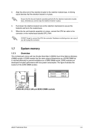
... the retention bracket in place, connect the CPU fan cable to plug this connector. 1.7 System memory 1.7.1 Overview This motherboard comes with less power consumption. Push down the retention bracket lock on the retention mechanism to secure the heatsink and fan...of the retention bracket to prevent installation on the motherboard labeled CPU_FAN. Align the other end of the DDR3 DIMM sockets: DIMM_A1 DIMM_B1 Channel Channel A Channel B Sockets DIMM_A1 DIMM_B1 F1A55-M LK R2.0 F1A55-M LK R2.0 240-pin DDR3 DIMM sockets ASUS F1A55-M LK R2.0 1-11 3. When the fan and heatsink ...
... the retention bracket in place, connect the CPU fan cable to plug this connector. 1.7 System memory 1.7.1 Overview This motherboard comes with less power consumption. Push down the retention bracket lock on the retention mechanism to secure the heatsink and fan...of the retention bracket to prevent installation on the motherboard labeled CPU_FAN. Align the other end of the DDR3 DIMM sockets: DIMM_A1 DIMM_B1 Channel Channel A Channel B Sockets DIMM_A1 DIMM_B1 F1A55-M LK R2.0 F1A55-M LK R2.0 240-pin DDR3 DIMM sockets ASUS F1A55-M LK R2.0 1-11 3. When the fan and heatsink ...
F1A55-M LK R2.0 User's Manual
Page 22
...) 6GB(3 x 2GB) 8GB(2 x 4GB) 8GB(2 x 4GB) 3GB(3 x 1GB) 6GB(3 x 2GB) SS/DS Chip Brand DS - Check with 16GB or above DIMMs. ASUS will update the memory QVL once the DIMMs are using a 32-bit Windows® OS. - Voltage 1.65V 1.65V 1.50V 1.5V 1.65V 1.65V DIMM socket support...memory on its Serial Presence Detect (SPD), which is then mapped for the OS can be about 3GB or less. Chip No. - F1A55-M LK R2.0 Motherboard Qualified Vendors Lists (QVL) DDR3-1866 MHz capability Vendors Part No. Under the default state, some memory modules for overclocking may install varying...
...) 6GB(3 x 2GB) 8GB(2 x 4GB) 8GB(2 x 4GB) 3GB(3 x 1GB) 6GB(3 x 2GB) SS/DS Chip Brand DS - Check with 16GB or above DIMMs. ASUS will update the memory QVL once the DIMMs are using a 32-bit Windows® OS. - Voltage 1.65V 1.65V 1.50V 1.5V 1.65V 1.65V DIMM socket support...memory on its Serial Presence Detect (SPD), which is then mapped for the OS can be about 3GB or less. Chip No. - F1A55-M LK R2.0 Motherboard Qualified Vendors Lists (QVL) DDR3-1866 MHz capability Vendors Part No. Under the default state, some memory modules for overclocking may install varying...

F1A55-M LK R2.0 User's Manual
Page 26
Press the retaining clips outward to both the motherboard and the components. 1. DO NOT force a DIMM into the socket 3 until the retaining clips snap back in place and the DIMM is keyed with extra ...
Press the retaining clips outward to both the motherboard and the components. 1. DO NOT force a DIMM into the socket 3 until the retaining clips snap back in place and the DIMM is keyed with extra ...
F1A55-M LK R2.0 User's Manual
Page 27
...as a LAN card, SCSI card, USB card, and other cards that comply with PCI specifications. 1.8.4 PCI Express x1 slot This motherboard supports PCI Express x1 network cards, SCSI cards, and other cards that comply with the PCI Express specifications. 1.8.5 PCI Express x16 slot This... cover. 1.8.2 Configuring an expansion card After installing the expansion card, configure it and make the necessary hardware settings for later use . ASUS F1A55-M LK R2.0 1-17 Remove the system unit cover (if your motherboard is completely seated on the system and change the necessary BIOS settings, if any.
...as a LAN card, SCSI card, USB card, and other cards that comply with PCI specifications. 1.8.4 PCI Express x1 slot This motherboard supports PCI Express x1 network cards, SCSI cards, and other cards that comply with the PCI Express specifications. 1.8.5 PCI Express x16 slot This... cover. 1.8.2 Configuring an expansion card After installing the expansion card, configure it and make the necessary hardware settings for later use . ASUS F1A55-M LK R2.0 1-17 Remove the system unit cover (if your motherboard is completely seated on the system and change the necessary BIOS settings, if any.
F1A55-M LK R2.0 User's Manual
Page 31
... PWR GND F1A55-M LK R2.0 CHA_FAN GND +12V Rotation F1A55-M LK R2.0 Fan connectors DO NOT forget to connect the fan cables to CRT and isn't compatible with DVI-I. 10. ASUS F1A55-M LK R2.0 1-21 This port is for USB USB 2.0/1.1 devices. 8. These are for a PS/2 keyboard. 1.10.2 Internal connectors 1. DVI-D port. DO NOT place jumper caps on the motherboard, ensuring...
... PWR GND F1A55-M LK R2.0 CHA_FAN GND +12V Rotation F1A55-M LK R2.0 Fan connectors DO NOT forget to connect the fan cables to CRT and isn't compatible with DVI-I. 10. ASUS F1A55-M LK R2.0 1-21 This port is for USB USB 2.0/1.1 devices. 8. These are for a PS/2 keyboard. 1.10.2 Internal connectors 1. DVI-D port. DO NOT place jumper caps on the motherboard, ensuring...
F1A55-M LK R2.0 User's Manual
Page 35
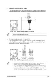
... of the motherboard's high-definition audio capability. • If you want to connect a high-definition front panel audio module to this connector is for details. If you want to connect an AC'97 front panel audio module to this connector. See section 2.5.5 Onboard Devices Configuration for a serial (COM) port. ASUS F1A55-M LK R2.0 1-25 Front...
... of the motherboard's high-definition audio capability. • If you want to connect a high-definition front panel audio module to this connector is for details. If you want to connect an AC'97 front panel audio module to this connector. See section 2.5.5 Onboard Devices Configuration for a serial (COM) port. ASUS F1A55-M LK R2.0 1-25 Front...

F1A55-M LK R2.0 User's Manual
Page 36
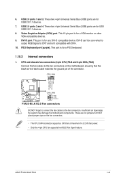
... USB56, USB78) These connectors are for USB 2.0 ports. USB78 USB56 USB+5V USB_P6USB_P6+ GND NC USB+5V USB_P8USB_P8+ GND NC F1A55-M LK R2.0 PIN 1 PIN 1 USB+5V USB_P5USB_P5+ GND USB+5V USB_P7USB_P7+ GND F1A55-M LK R2.0 USB2.0 connectors Never connect a 1394 cable to a slot opening at the back of the system chassis. Connect the USB module... purchased separately. 1-26 Chapter 1: Product introduction These USB connectors comply with USB 2.0 specification that supports up to 480Mbps connection speed. Doing so will damage the motherboard!
... USB56, USB78) These connectors are for USB 2.0 ports. USB78 USB56 USB+5V USB_P6USB_P6+ GND NC USB+5V USB_P8USB_P8+ GND NC F1A55-M LK R2.0 PIN 1 PIN 1 USB+5V USB_P5USB_P5+ GND USB+5V USB_P7USB_P7+ GND F1A55-M LK R2.0 USB2.0 connectors Never connect a 1394 cable to a slot opening at the back of the system chassis. Connect the USB module... purchased separately. 1-26 Chapter 1: Product introduction These USB connectors comply with USB 2.0 specification that supports up to 480Mbps connection speed. Doing so will damage the motherboard!


