User Manual
Page 2
...you wish to obtain the corresponding source code and your contact details so that is valid to anyone in this email address). SPECIFICATIONS AND INFORMATION CONTAINED IN THIS MANUAL ARE FURNISHED FOR INFORMATIONAL USE ONLY, AND ARE SUBJECT TO CHANGE AT ANY TIME WITHOUT NOTICE,... provide the name, model number and version, as required under various Free Open Source Software licenses. Copies of ASUSTeK Computer Inc. ("ASUS"). Offer to infringe. ii No part of Certain Software This product may obtain the complete corresponding source code (as the corresponding binary/object...
...you wish to obtain the corresponding source code and your contact details so that is valid to anyone in this email address). SPECIFICATIONS AND INFORMATION CONTAINED IN THIS MANUAL ARE FURNISHED FOR INFORMATIONAL USE ONLY, AND ARE SUBJECT TO CHANGE AT ANY TIME WITHOUT NOTICE,... provide the name, model number and version, as required under various Free Open Source Software licenses. Copies of ASUSTeK Computer Inc. ("ASUS"). Offer to infringe. ii No part of Certain Software This product may obtain the complete corresponding source code (as the corresponding binary/object...
User Manual
Page 3
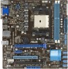
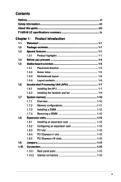
Contents Notices...vi Safety information vii About this guide viii F1A55-M LE specifications summary ix Chapter 1: Product introduction 1.1 Welcome 1-1 1.2 Package contents 1-1 1.3 Special features 1-1 1.3.1 Product highlights 1-1 1.4 Before you proceed 1-4 1.5 Motherboard overview 1-5 1.5.1 Placement direction 1-5 1.5.2 Screw holes 1-5 1.5.3 Motherboard layout 1-6 1.5.4 Layout contents 1-6 1.6 ...
Contents Notices...vi Safety information vii About this guide viii F1A55-M LE specifications summary ix Chapter 1: Product introduction 1.1 Welcome 1-1 1.2 Package contents 1-1 1.3 Special features 1-1 1.3.1 Product highlights 1-1 1.4 Before you proceed 1-4 1.5 Motherboard overview 1-5 1.5.1 Placement direction 1-5 1.5.2 Screw holes 1-5 1.5.3 Motherboard layout 1-6 1.5.4 Layout contents 1-6 1.6 ...
User Manual
Page 9
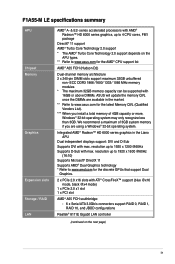
... connectors support RAID 0, RAID 1, RAID 10, and JBOD configurations Realtek® 8111E Gigabit LAN controller (continued on the APU types. ** Refer to www.asus.com for the AMD® CPU support list AMD® A55 FCH (Hudson D2) Dual-channel memory architecture 2 x 240-pin DIMM slots support maximum ...; Turbo Core Technology 2.0 support * The AMD® Turbo Core Technology 2.0 support depends on the next page) ix series accelerated processors with max. F1A55-M LE specifications summary APU Chipset Memory Graphics Expansion slots Storage / RAID LAN AMD® A- & E2-
... connectors support RAID 0, RAID 1, RAID 10, and JBOD configurations Realtek® 8111E Gigabit LAN controller (continued on the APU types. ** Refer to www.asus.com for the AMD® CPU support list AMD® A55 FCH (Hudson D2) Dual-channel memory architecture 2 x 240-pin DIMM slots support maximum ...; Turbo Core Technology 2.0 support * The AMD® Turbo Core Technology 2.0 support depends on the next page) ix series accelerated processors with max. F1A55-M LE specifications summary APU Chipset Memory Graphics Expansion slots Storage / RAID LAN AMD® A- & E2-

User Manual
Page 10
...% All high-quality conductive polymer conductors Precision Tweaker 2 - ASUS CrashFree BIOS 3 - Supports S/PDIF out interface onboard AMD® A55 FCH southbridge: - 12 x USB 2.0/1.1 ports (6 ports at the mid-board, 6 ports at the back panel) ASUS Unique Technology - F1A55-M LE specifications summary Audio USB ASUS unique features Special features ASUS exclusive overclocking features Realtek ALC887 3-jack 8-channel High...
...% All high-quality conductive polymer conductors Precision Tweaker 2 - ASUS CrashFree BIOS 3 - Supports S/PDIF out interface onboard AMD® A55 FCH southbridge: - 12 x USB 2.0/1.1 ports (6 ports at the mid-board, 6 ports at the back panel) ASUS Unique Technology - F1A55-M LE specifications summary Audio USB ASUS unique features Special features ASUS exclusive overclocking features Realtek ALC887 3-jack 8-channel High...
User Manual
Page 11
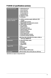
xi F1A55-M LE specifications summary Back Panel I/O ports 1 x PS/2 keyboard port 1 x PS/2 mouse port 1 x DVI-D output port 1 x D-Sub output port 1 x LAN (RJ-45) port 6 x USB 2.0/1.1 ports 3 x Audio jacks Internal I/O ... 12V power connector 32Mb Flash ROM, UEFI BIOS, PnP, DMI 2.0, WfM 2.0, ACPI 2.0a, SM BIOS 2.6 2 x Serial ATA 3.0Gb/s cables 1 x I/O shield 1 x User Manual 1 x Support DVD Drivers ASUS PC Probe II ASUS Update Anti-Virus software (OEM version) uATX form factor: 9.6 in x 9.0 in (24.4 cm x 22.9 cm) *Specifications are subject to change without notice.
xi F1A55-M LE specifications summary Back Panel I/O ports 1 x PS/2 keyboard port 1 x PS/2 mouse port 1 x DVI-D output port 1 x D-Sub output port 1 x LAN (RJ-45) port 6 x USB 2.0/1.1 ports 3 x Audio jacks Internal I/O ... 12V power connector 32Mb Flash ROM, UEFI BIOS, PnP, DMI 2.0, WfM 2.0, ACPI 2.0a, SM BIOS 2.6 2 x Serial ATA 3.0Gb/s cables 1 x I/O shield 1 x User Manual 1 x Support DVD Drivers ASUS PC Probe II ASUS Update Anti-Virus software (OEM version) uATX form factor: 9.6 in x 9.0 in (24.4 cm x 22.9 cm) *Specifications are subject to change without notice.
User Manual
Page 25
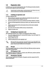
...1.8.3 PCI slot The PCI slot supports cards such as a LAN card, SCSI card, USB card, and other cards that comply with PCI specifications. 1.8.4 PCI Express x1 slot This motherboard supports PCI Express x1 network cards, SCSI cards, and other cards that comply with the PCI Express...Share IRQ" or that they support. See Chapter 2 for the card. 2. When using PCI cards on BIOS setup. 2. ASUS F1A55-M LE 1-13 Align the card connector with the PCI Express specifications. Keep the screw for the expansion card. Assign an IRQ to use . 4. Remove the system unit cover (if your motherboard...
...1.8.3 PCI slot The PCI slot supports cards such as a LAN card, SCSI card, USB card, and other cards that comply with PCI specifications. 1.8.4 PCI Express x1 slot This motherboard supports PCI Express x1 network cards, SCSI cards, and other cards that comply with the PCI Express...Share IRQ" or that they support. See Chapter 2 for the card. 2. When using PCI cards on BIOS setup. 2. ASUS F1A55-M LE 1-13 Align the card connector with the PCI Express specifications. Keep the screw for the expansion card. Assign an IRQ to use . 4. Remove the system unit cover (if your motherboard...

User Manual
Page 29
... the power is inadequate. • If you intend to connect the 4-pin ATX +12V power plug. The speaker allows you use an ATX 12V Specification 2.0‑compliant power supply unit (PSU) with a minimum of 300W. Otherwise, the system will not boot up. • We recommend that you... to the Recommended Power Supply Wattage Calculator at least 15 A on +12 V and that you to fit these connectors in only one orientation. ASUS F1A55-M LE 1-17 Speaker connector (4-pin SPEAKER) This 4-pin connector is inadequate. • DO NOT forget to install additional devices. This PSU type has ...
... the power is inadequate. • If you intend to connect the 4-pin ATX +12V power plug. The speaker allows you use an ATX 12V Specification 2.0‑compliant power supply unit (PSU) with a minimum of 300W. Otherwise, the system will not boot up. • We recommend that you... to the Recommended Power Supply Wattage Calculator at least 15 A on +12 V and that you to fit these connectors in only one orientation. ASUS F1A55-M LE 1-17 Speaker connector (4-pin SPEAKER) This 4-pin connector is inadequate. • DO NOT forget to install additional devices. This PSU type has ...
User Manual
Page 33
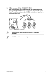
Connect the USB module cable to any of the system chassis. ASUS F1A55-M LE 1-21 10. USB 2.0 connectors (10-1 pin USB56, USB78, USB910) These connectors are for USB 2.0 ports. Never connect a 1394 cable to a slot opening at the back of these connectors, then install the module to the USB connectors. These USB connectors comply with USB 2.0 specification that supports up to 480Mbps connection speed. The USB 2.0 module is purchased separately. Doing so will damage the motherboard!
Connect the USB module cable to any of the system chassis. ASUS F1A55-M LE 1-21 10. USB 2.0 connectors (10-1 pin USB56, USB78, USB910) These connectors are for USB 2.0 ports. Never connect a 1394 cable to a slot opening at the back of these connectors, then install the module to the USB connectors. These USB connectors comply with USB 2.0 specification that supports up to 480Mbps connection speed. The USB 2.0 module is purchased separately. Doing so will damage the motherboard!
User Manual
Page 44
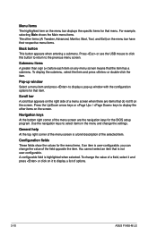
...example, selecting Main shows the Main menu items. The other items on the screen. Navigation keys At the bottom right corner of options. 2-10 ASUS F1A55-M LE General help At the top right corner of the menu screen is user-configurable, you can change the value of the selected item. A configurable ...items. If an item is a brief description of the field opposite the item. Menu items The highlighted item on the menu bar displays the specific items for that item. Press or use the USB mouse to click this button to return to display a pop-up window with the configuration...
...example, selecting Main shows the Main menu items. The other items on the screen. Navigation keys At the bottom right corner of options. 2-10 ASUS F1A55-M LE General help At the top right corner of the menu screen is user-configurable, you can change the value of the selected item. A configurable ...items. If an item is a brief description of the field opposite the item. Menu items The highlighted item on the menu bar displays the specific items for that item. Press or use the USB mouse to click this button to return to display a pop-up window with the configuration...

User Manual
Page 49
... Offset Mode Sign [+] [+] To offset the voltage by a positive value. [-] To offset the voltage by a negative value. The values range from 1.35V to Intel CPU specification, DIMMs with a 0.01V interval. According to 2.30V with voltage requirement over 1.65V may damage the CPU permanently.
... Offset Mode Sign [+] [+] To offset the voltage by a positive value. [-] To offset the voltage by a negative value. The values range from 1.35V to Intel CPU specification, DIMMs with a 0.01V interval. According to 2.30V with voltage requirement over 1.65V may damage the CPU permanently.
User Manual
Page 50
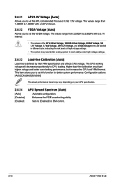
... items are labeled in different color, indicating the risk levels of high voltage settings. • The system may vary depending on your CPU specification. 2.4.14 APU Spread Spectrum [Auto] [Auto] Automatic configuration. [Disabled] Enhances the PCIE overclocking ability. [Enabled] Sets to [Enabled] .... 2.4.13 Load-line Calibration [Auto] Load-line is defined by Intel VRM specification and affects CPU voltage. 2.4.11 APU1.2V Voltage [Auto] Allows you to set this function for EMI control. 2-16 ASUS F1A55-M LE The values range from 2.5000V to 2.8000V with a 0.01V interval. 2.4.12...
... items are labeled in different color, indicating the risk levels of high voltage settings. • The system may vary depending on your CPU specification. 2.4.14 APU Spread Spectrum [Auto] [Auto] Automatic configuration. [Disabled] Enhances the PCIE overclocking ability. [Enabled] Sets to [Enabled] .... 2.4.13 Load-line Calibration [Auto] Load-line is defined by Intel VRM specification and affects CPU voltage. 2.4.11 APU1.2V Voltage [Auto] Allows you to set this function for EMI control. 2-16 ASUS F1A55-M LE The values range from 2.5000V to 2.8000V with a 0.01V interval. 2.4.12...
User Manual
Page 64
... received, including interference that the product Product Name : Motherboard Model Number : F1A55-M LE Conforms to begin affixing CE marking:2011 Signature Country: TAIWAN Authorized representative in Europe: ASUS COMPUTER GmbH Address, City: HARKORT STR. 21-23, 40880 RATINGEN Country: ...11, 2011 Year to the following two conditions: (1) This device may cause undesired operation. Operation is subject to the following specifications: FCC Part 15, Subpart B, Unintentional Radiators FCC Part 15, Subpart C, Intentional Radiators FCC Part 15, Subpart E, Intentional ...
... received, including interference that the product Product Name : Motherboard Model Number : F1A55-M LE Conforms to begin affixing CE marking:2011 Signature Country: TAIWAN Authorized representative in Europe: ASUS COMPUTER GmbH Address, City: HARKORT STR. 21-23, 40880 RATINGEN Country: ...11, 2011 Year to the following two conditions: (1) This device may cause undesired operation. Operation is subject to the following specifications: FCC Part 15, Subpart B, Unintentional Radiators FCC Part 15, Subpart C, Intentional Radiators FCC Part 15, Subpart E, Intentional ...
