User Guide
Page 4
... 2-44 2.10.1 Using the OS shut down function 2-44 2.10.2 Using the dual function power switch 2-44 Chapter 3: BIOS setup 3.1 Managing and updating your BIOS 3-1 3.1.1 ASUS Update utility 3-1 3.1.2 ASUS EZ Flash 2 utility 3-4 3.1.3 ASUS CrashFree BIOS 3 utility 3-5 3.2 BIOS setup program 3-6 3.2.1 BIOS menu screen 3-7 3.2.2 Menu bar 3-7 3.2.3 Navigation keys 3-7 3.2.4 Menu items 3-8 3.2.5 Submenu items 3-8 3.2.6 Configuration fields 3-8 3.2.7 Pop-up window 3-8 3.2.8 Scroll bar 3-8 3.2.9 General...
... 2-44 2.10.1 Using the OS shut down function 2-44 2.10.2 Using the dual function power switch 2-44 Chapter 3: BIOS setup 3.1 Managing and updating your BIOS 3-1 3.1.1 ASUS Update utility 3-1 3.1.2 ASUS EZ Flash 2 utility 3-4 3.1.3 ASUS CrashFree BIOS 3 utility 3-5 3.2 BIOS setup program 3-6 3.2.1 BIOS menu screen 3-7 3.2.2 Menu bar 3-7 3.2.3 Navigation keys 3-7 3.2.4 Menu items 3-8 3.2.5 Submenu items 3-8 3.2.6 Configuration fields 3-8 3.2.7 Pop-up window 3-8 3.2.8 Scroll bar 3-8 3.2.9 General...
User Guide
Page 7
... 4-9 4.3.2 Sound Blaster X-Fi audio utility 4-11 4.3.3 ASUS PC Probe II 4-15 4.3.4 ASUS AI Suite 4-21 4.3.5 ASUS Q-Fan 2 4-23 4.3.6 CPU Level Up 4-24 4.3.7 ASUS TurboV 4-25 4.4 RAID configurations 4-27 4.4.1 RAID definitions 4-27 4.4.2 Installing Serial ATA hard disks 4-28 4.4.3 Setting the RAID item in BIOS 4-28 4.4.4 AMD® Option ROM Utility 4-28 4.5 Creating a RAID driver disk 4-32...
... 4-9 4.3.2 Sound Blaster X-Fi audio utility 4-11 4.3.3 ASUS PC Probe II 4-15 4.3.4 ASUS AI Suite 4-21 4.3.5 ASUS Q-Fan 2 4-23 4.3.6 CPU Level Up 4-24 4.3.7 ASUS TurboV 4-25 4.4 RAID configurations 4-27 4.4.1 RAID definitions 4-27 4.4.2 Installing Serial ATA hard disks 4-28 4.4.3 Setting the RAID item in BIOS 4-28 4.4.4 AMD® Option ROM Utility 4-28 4.5 Creating a RAID driver disk 4-32...
User Guide
Page 11
... code table The Appendix lists the debug code table for product and software updates. 1. ASUS websites The ASUS website provides updated information on the motherboard. • Chapter 3: BIOS setup This chapter tells how to change system settings through the BIOS Setup menus. xi Optional documentation Your product package may have to perform when installing system...
... code table The Appendix lists the debug code table for product and software updates. 1. ASUS websites The ASUS website provides updated information on the motherboard. • Chapter 3: BIOS setup This chapter tells how to change system settings through the BIOS Setup menus. xi Optional documentation Your product package may have to perform when installing system...
User Guide
Page 14
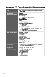
... 6 x USB 2.0/1.1 ports 1 x IEEE1394a port 1 x Clr CMOS switch (continued on the next page) xiv COP EX (Component Overheat Protection - EX) - ASUS TurboV - Crosshair III Formula specifications summary USB ROG Exclusive Overclocking Features Other Special Features BIOS Features Manageability Back Panel I/O Ports max. 12 USB 2.0 ports (6 ports at mid-board, 6 ports at ��b�a�c�...
... 6 x USB 2.0/1.1 ports 1 x IEEE1394a port 1 x Clr CMOS switch (continued on the next page) xiv COP EX (Component Overheat Protection - EX) - ASUS TurboV - Crosshair III Formula specifications summary USB ROG Exclusive Overclocking Features Other Special Features BIOS Features Manageability Back Panel I/O Ports max. 12 USB 2.0 ports (6 ports at mid-board, 6 ports at ��b�a�c�...
User Guide
Page 24
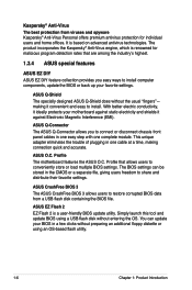
... an OS-based flash utility. 1-6 Chapter 1: Product Introduction The BIOS settings can update your motherboard against Electronic Magnetic Interference (EMI). ASUS EZ Flash 2 EZ Flash 2 is based on advanced antivirus technologies. It is a user-friendly BIOS update utility. ASUS Q-Connector The ASUS Q-Connector allows you easy ways to install. The product incorporates the Kaspersky® Anti...
... an OS-based flash utility. 1-6 Chapter 1: Product Introduction The BIOS settings can update your motherboard against Electronic Magnetic Interference (EMI). ASUS EZ Flash 2 EZ Flash 2 is based on advanced antivirus technologies. It is a user-friendly BIOS update utility. ASUS Q-Connector The ASUS Q-Connector allows you easy ways to install. The product incorporates the Kaspersky® Anti...
User Guide
Page 25
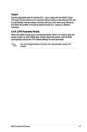
... before using C.P.R. Simply reboot the system, and the BIOS automatically restores the CPU default settings for each parameter. ROG Crosshair III Formula 1-7 settings in TurboV provides the best O.C. function. and its user-friendly interface makes overclock with the ASUS TurboV. Due to the chipset behavior, AC power off... TurboV Feel the adrenaline rush of real-time OC-now a reality with just a few clicks away. Moreover, the ASUS OC profiles in different scenarios. C.P.R. (CPU Parameter Recall) When the system hangs due to overclock without exiting or rebooting the OS;
... before using C.P.R. Simply reboot the system, and the BIOS automatically restores the CPU default settings for each parameter. ROG Crosshair III Formula 1-7 settings in TurboV provides the best O.C. function. and its user-friendly interface makes overclock with the ASUS TurboV. Due to the chipset behavior, AC power off... TurboV Feel the adrenaline rush of real-time OC-now a reality with just a few clicks away. Moreover, the ASUS OC profiles in different scenarios. C.P.R. (CPU Parameter Recall) When the system hangs due to overclock without exiting or rebooting the OS;
User Guide
Page 30
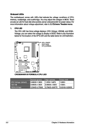
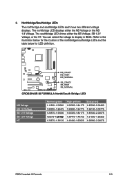
Onboard LEDs The motherboard comes with LEDs that indicate the voltage conditions of the CPU LED and the table below for the location of CPU, memory, northbridge, and southbridge. ... 2.50425-2.75600 High (yellow) 1.3750-1.4875 0.85000-1.3625 2.76925-3.00775 Crazy (red) 1.5000- 1.5000- 3.02100-3.20650 2-2 Chapter 2: Hardware information You may adjust the voltages in BIOS. For more information about voltage adjustment, refer to display in...
Onboard LEDs The motherboard comes with LEDs that indicate the voltage conditions of the CPU LED and the table below for the location of CPU, memory, northbridge, and southbridge. ... 2.50425-2.75600 High (yellow) 1.3750-1.4875 0.85000-1.3625 2.76925-3.00775 Crazy (red) 1.5000- 1.5000- 3.02100-3.20650 2-2 Chapter 2: Hardware information You may adjust the voltages in BIOS. For more information about voltage adjustment, refer to display in...
User Guide
Page 31
...60325-1.84175 1.90800-1.94775 1.60325-1.84175 1.36475-1.49725 1.40450-1.65625 Crazy (red) 1.85500-2.05400 1.96100-3.00775 1.85500-2.00075 1.51050-1.60325 1.66950-2.00075 ROG Crosshair III Formula 2-3 The northbridge LED displays either the SB Voltage, SB 1.2V Voltage, or the HT. The southbridge LED shows either the NB Voltage or the NB... illustration below for the location of the northbridge/southbridge LEDs and the table below for LED definition. Refer to display in BIOS. Northbridge/Southbridge LEDs The northbridge and southbridge LEDs each have two different voltage displays.
...60325-1.84175 1.90800-1.94775 1.60325-1.84175 1.36475-1.49725 1.40450-1.65625 Crazy (red) 1.85500-2.05400 1.96100-3.00775 1.85500-2.00075 1.51050-1.60325 1.66950-2.00075 ROG Crosshair III Formula 2-3 The northbridge LED displays either the SB Voltage, SB 1.2V Voltage, or the HT. The southbridge LED shows either the NB Voltage or the NB... illustration below for the location of the northbridge/southbridge LEDs and the table below for LED definition. Refer to display in BIOS. Northbridge/Southbridge LEDs The northbridge and southbridge LEDs each have two different voltage displays.
User Guide
Page 49
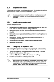
...and the card inoperable. ROG Crosshair III Formula 2-21 The following sub‑sections describe the slots and the expansion cards that you intend to the tables on BIOS setup. 2. 2.5 Expansion slots In the future, you may cause you physical injury and damage motherboard components. 2.5.1 Installing an ...expansion card To install an expansion card: 1. Failure to do not need to the table on the system and change the necessary BIOS settings, if any. Turn on the next page ...
...and the card inoperable. ROG Crosshair III Formula 2-21 The following sub‑sections describe the slots and the expansion cards that you intend to the tables on BIOS setup. 2. 2.5 Expansion slots In the future, you may cause you physical injury and damage motherboard components. 2.5.1 Installing an ...expansion card To install an expansion card: 1. Failure to do not need to the table on the system and change the necessary BIOS settings, if any. Turn on the next page ...
User Guide
Page 53
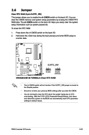
... clr CMOS switch on the back I /O. With the C.P.R. (CPU Parameter Recall) feature, shut down the key during the boot process and enter BIOS setup to re-enter data. • The clr CMOS switch will not function if the CLRTC_SW jumper is moved to the Disable position. •... reset CPU parameter settings to default values. Hold down and reboot the system so the BIOS can clear the CMOS memory and system setup parameters by erasing the CMOS RTC RAM data. ROG Crosshair III Formula 2-25 2.6 Jumper Clear RTC RAM (3-pin CLRTC_SW) This jumper allows you clear the CMOS...
... clr CMOS switch on the back I /O. With the C.P.R. (CPU Parameter Recall) feature, shut down the key during the boot process and enter BIOS setup to re-enter data. • The clr CMOS switch will not function if the CLRTC_SW jumper is moved to the Disable position. •... reset CPU parameter settings to default values. Hold down and reboot the system so the BIOS can clear the CMOS memory and system setup parameters by erasing the CMOS RTC RAM data. ROG Crosshair III Formula 2-25 2.6 Jumper Clear RTC RAM (3-pin CLRTC_SW) This jumper allows you clear the CMOS...
User Guide
Page 56
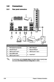
USB 2.0 ports 3 and 4 6. External SATA port 8. See section 3.5.3 Onboard Devices Configuration for details. 2-28 Chapter 2: Hardware information USB 2.0 ports 5 and 6 4. PS/2 keyboard port (purple) 2. LAN (RJ-45) port* 3. Audio Ports** To use hot-plug, set the Controller Mode in the BIOS settings to [AHCI] mode. Clear CMOS switch 5. 2.8 Connectors 2.8.1 Rear panel connectors Rear panel connectors 1. IEEE 1394a port 7. USB 2.0 ports 1 and 2 9.
USB 2.0 ports 3 and 4 6. External SATA port 8. See section 3.5.3 Onboard Devices Configuration for details. 2-28 Chapter 2: Hardware information USB 2.0 ports 5 and 6 4. PS/2 keyboard port (purple) 2. LAN (RJ-45) port* 3. Audio Ports** To use hot-plug, set the Controller Mode in the BIOS settings to [AHCI] mode. Clear CMOS switch 5. 2.8 Connectors 2.8.1 Rear panel connectors Rear panel connectors 1. IEEE 1394a port 7. USB 2.0 ports 1 and 2 9.
User Guide
Page 59
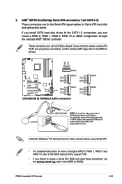
... connectors are set to [RAID]. If you intend to create a Serial ATA RAID set using these connectors, set the OnChip SATA Type item in the BIOS to the SATA1-5 connectors, you can create a RAID 0, RAID 1, RAID 5, RAID 10 or JBOD configuration through the onboard AMD® SB750 controller. These connectors are... 0, RAID 1, RAID 5 and RAID 10, refer to the RAID manual in the support DVD. • If you install SATA hard disk drives to [RAID]. ROG Crosshair III Formula 2-31 If you intend to create a Serial ATA RAID set using these connectors, set the Onchip SATA Type item in the...
... connectors are set to [RAID]. If you intend to create a Serial ATA RAID set using these connectors, set the OnChip SATA Type item in the BIOS to the SATA1-5 connectors, you can create a RAID 0, RAID 1, RAID 5, RAID 10 or JBOD configuration through the onboard AMD® SB750 controller. These connectors are... 0, RAID 1, RAID 5 and RAID 10, refer to the RAID manual in the support DVD. • If you install SATA hard disk drives to [RAID]. ROG Crosshair III Formula 2-31 If you intend to create a Serial ATA RAID set using these connectors, set the Onchip SATA Type item in the...
User Guide
Page 64
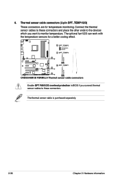
The optional fan1/2/3 can work with the temperature sensors for temperature monitoring. Connect the thermal sensor cables to these connectors. The thermal sensor cable is purchased separately. 2-36 Chapter 2: Hardware information Enable OPT FAN1/2/3 overheat protection in BIOS if you want to these connectors and place the other ends to the devices which you connect thermal sensor cables to monitor temperature. 8. Thermal sensor cable connectors (2-pin OPT_TEMP1/2/3) These connectors are for a better cooling effect.
The optional fan1/2/3 can work with the temperature sensors for temperature monitoring. Connect the thermal sensor cables to these connectors. The thermal sensor cable is purchased separately. 2-36 Chapter 2: Hardware information Enable OPT FAN1/2/3 overheat protection in BIOS if you want to these connectors and place the other ends to the devices which you connect thermal sensor cables to monitor temperature. 8. Thermal sensor cable connectors (2-pin OPT_TEMP1/2/3) These connectors are for a better cooling effect.
User Guide
Page 66
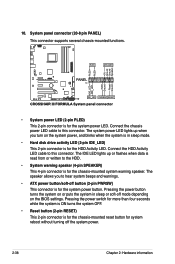
... hear system beeps and warnings. • ATX power button/soft-off the system power. 2-38 Chapter 2: Hardware information The speaker allows you turn on the BIOS settings. 10. System panel connector (20-8 pin PANEL) This connector supports several chassis-mounted functions. • System power LED (2-pin PLED) This 2-pin connector is...
... hear system beeps and warnings. • ATX power button/soft-off the system power. 2-38 Chapter 2: Hardware information The speaker allows you turn on the BIOS settings. 10. System panel connector (20-8 pin PANEL) This connector supports several chassis-mounted functions. • System power LED (2-pin PLED) This 2-pin connector is...
User Guide
Page 71
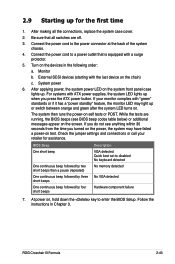
.... 2. System power 6. 2.9 Starting up for assistance. Connect the power cord to enter the BIOS Setup. If you do not see BIOS beep codes table below) or additional messages appear on test. At power on the devices in Chapter 3. ROG Crosshair III Formula 2-43 Be sure that is equipped with ATX power supplies, the system LED...
.... 2. System power 6. 2.9 Starting up for assistance. Connect the power cord to enter the BIOS Setup. If you do not see BIOS beep codes table below) or additional messages appear on test. At power on the devices in Chapter 3. ROG Crosshair III Formula 2-43 Be sure that is equipped with ATX power supplies, the system LED...

User Guide
Page 72
... to section 3.6 Power Menu in Chapter 3 for more than four seconds puts the system to sleep mode or to soft-off mode regardless of the BIOS setting. Click the Start button then select Shut Down. 2. The power supply should turn off the computer 2.10.1 Using the OS shut down function If... While the system is ON, pressing the power switch for less than four seconds lets the system enter the soft-off mode, depending on the BIOS setting.
... to section 3.6 Power Menu in Chapter 3 for more than four seconds puts the system to sleep mode or to soft-off mode regardless of the BIOS setting. Click the Start button then select Shut Down. 2. The power supply should turn off the computer 2.10.1 Using the OS shut down function If... While the system is ON, pressing the power switch for less than four seconds lets the system enter the soft-off mode, depending on the BIOS setting.
User Guide
Page 73
Detailed descriptions of the BIOS parameters are also provided. This chapter tells how to change the BIOS se3tup system settings through the BIOS Setup menus.
Detailed descriptions of the BIOS parameters are also provided. This chapter tells how to change the BIOS se3tup system settings through the BIOS Setup menus.
User Guide
Page 74
Chapter summary 3 3.1 Managing and updating your BIOS 3-1 3.2 BIOS setup program 3-6 3.3 Extreme Tweaker menu 3-9 3.4 Main menu 3-18 3.5 Advanced menu 3-23 3.6 Power menu 3-33 3.7 Boot menu 3-39 3.8 Tools menu 3-43 3.9 Exit menu 3-47 ROG Crosshair III Formula
Chapter summary 3 3.1 Managing and updating your BIOS 3-1 3.2 BIOS setup program 3-6 3.3 Extreme Tweaker menu 3-9 3.4 Main menu 3-18 3.5 Advanced menu 3-23 3.6 Power menu 3-33 3.7 Boot menu 3-39 3.8 Tools menu 3-43 3.9 Exit menu 3-47 ROG Crosshair III Formula
User Guide
Page 75
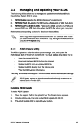
...). Place the support DVD in Windows® environment.) 2. ROG Crosshair III Formula 3-1 This utility is a utility that allows you to manage and update the motherboard Basic Input/Output System (BIOS) setup. 1. ASUS Update (Updates the BIOS in the optical drive. Copy the original motherboard BIOS using the ASUS Update utility. 3.1.1 ASUS Update utility The ASUS Update is available in the future. The...
...). Place the support DVD in Windows® environment.) 2. ROG Crosshair III Formula 3-1 This utility is a utility that allows you to manage and update the motherboard Basic Input/Output System (BIOS) setup. 1. ASUS Update (Updates the BIOS in the optical drive. Copy the original motherboard BIOS using the ASUS Update utility. 3.1.1 ASUS Update utility The ASUS Update is available in the future. The...
User Guide
Page 76
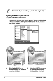
Updating the BIOS through the Internet To update the BIOS through the Internet: 1. Launch the ASUS Update utility from the 3. Select Update BIOS from the Windows® desktop by clicking Start > Programs > ASUS > ASUSUpdate > ASUSUpdate. Quit all Windows® applications before you to avoid network traffic, or menu, then click Next. Select the ASUS FTP site nearest Internet option from the drop‑down you update the BIOS using this utility. click Auto Select. Click Next. 3-2 Chapter 3: BIOS setup The ASUS Update main window appears. 2.
Updating the BIOS through the Internet To update the BIOS through the Internet: 1. Launch the ASUS Update utility from the 3. Select Update BIOS from the Windows® desktop by clicking Start > Programs > ASUS > ASUSUpdate > ASUSUpdate. Quit all Windows® applications before you to avoid network traffic, or menu, then click Next. Select the ASUS FTP site nearest Internet option from the drop‑down you update the BIOS using this utility. click Auto Select. Click Next. 3-2 Chapter 3: BIOS setup The ASUS Update main window appears. 2.


