
Users manual English
Page 1
Motherboard B150 PRO GAMING
Motherboard B150 PRO GAMING

Users manual English
Page 3
Contents Safety information iv About this guide iv Package contents vi B150 PRO GAMING specifications summary vi Chapter 1: Product introduction 1.1 Before you proceed 1-1 1.2 Motherboard overview 1-1 1.3 Central Processing Unit (CPU 1-3 1.4 System memory 1-7 1.5 Expansion slots 1-12 1.6 Jumpers 1-14 1.7 Connectors 1-15 1.8 Onboard LED 1-25 1.9 Software support 1-27 Chapter 2: BIOS ...menu 2-24 2.7 Monitor menu 2-32 2.8 Boot menu 2-36 2.9 Tool menu 2-40 2.10 Exit menu 2-42 2.11 Installing an operating system 2-43 Appendices Notices...A-1 ASUS contact information A-4 iii
Contents Safety information iv About this guide iv Package contents vi B150 PRO GAMING specifications summary vi Chapter 1: Product introduction 1.1 Before you proceed 1-1 1.2 Motherboard overview 1-1 1.3 Central Processing Unit (CPU 1-3 1.4 System memory 1-7 1.5 Expansion slots 1-12 1.6 Jumpers 1-14 1.7 Connectors 1-15 1.8 Onboard LED 1-25 1.9 Software support 1-27 Chapter 2: BIOS ...menu 2-24 2.7 Monitor menu 2-32 2.8 Boot menu 2-36 2.9 Tool menu 2-40 2.10 Exit menu 2-42 2.11 Installing an operating system 2-43 Appendices Notices...A-1 ASUS contact information A-4 iii
Users manual English
Page 4
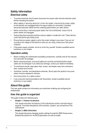
... connectors, slots, sockets and circuitry. • Avoid dust, humidity, and temperature extremes. Operation safety • Before installing the motherboard and adding components, carefully read all the manuals that came with the product, contact a qualified service technician or your area. It...features of the switches, jumpers, and connectors on a stable surface. • If you need when installing and configuring the motherboard. Detailed descriptions for the devices are unplugged before the signal cables are unplugged. • Seek professional assistance before you detect ...
... connectors, slots, sockets and circuitry. • Avoid dust, humidity, and temperature extremes. Operation safety • Before installing the motherboard and adding components, carefully read all the manuals that came with the product, contact a qualified service technician or your area. It...features of the switches, jumpers, and connectors on a stable surface. • If you need when installing and configuring the motherboard. Detailed descriptions for the devices are unplugged before the signal cables are unplugged. • Seek professional assistance before you detect ...

Users manual English
Page 6
B150 PRO GAMING specifications summary CPU Chipset Memory Graphics Multi-GPU Support Expansion slots LGA1151 socket for Intel® CPU support list. Supports HDMI 1.4b with ...your motherboard package for the Memory QVL (Qualified Vendors List). B150 PRO GAMING 4 x Serial ATA 6.0 Gb/s cables 1 x I/O Shield 1 x PRO GAMING cable labels 1 x M.2 screw package 1 x pack of cable tie Support DVD User Guide If any of the above items is subject to www.asus.com or this user manual for the following items. Motherboard Cables Accessories Application DVD Documentation ASUS Gaming Motherboard ...
B150 PRO GAMING specifications summary CPU Chipset Memory Graphics Multi-GPU Support Expansion slots LGA1151 socket for Intel® CPU support list. Supports HDMI 1.4b with ...your motherboard package for the Memory QVL (Qualified Vendors List). B150 PRO GAMING 4 x Serial ATA 6.0 Gb/s cables 1 x I/O Shield 1 x PRO GAMING cable labels 1 x M.2 screw package 1 x pack of cable tie Support DVD User Guide If any of the above items is subject to www.asus.com or this user manual for the following items. Motherboard Cables Accessories Application DVD Documentation ASUS Gaming Motherboard ...

Users manual English
Page 9
...to avoid damaging them due to the chassis. Product introduction 1 1.1 Before you proceed Take note of the following precautions before you install motherboard components or change any motherboard settings. • Unplug the power cord from the power supply. Doing so can cause you install or remove any component. •... ATX power supply is switched off or the power cord is detached from the wall socket before installing or removing the motherboard. Do not overtighten the screws! ASUS B150 PRO GAMING 1-1 Unplug the power cord before touching any component, ensure that the...
...to avoid damaging them due to the chassis. Product introduction 1 1.1 Before you proceed Take note of the following precautions before you install motherboard components or change any motherboard settings. • Unplug the power cord from the power supply. Doing so can cause you install or remove any component. •... ATX power supply is switched off or the power cord is detached from the wall socket before installing or removing the motherboard. Do not overtighten the screws! ASUS B150 PRO GAMING 1-1 Unplug the power cord before touching any component, ensure that the...
Users manual English
Page 10
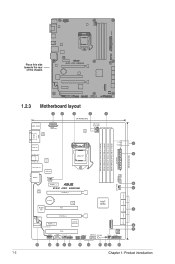
Place this side towards the rear of the chassis 1.2.3 Motherboard layout 1 2 KBMS_USB78 ASM 1442K EATX12V 3 2 4 24.4cm(9.6in) CPU_FAN W_PUMP DIGI +VRM HDMI VGA USB3_56 USB3.1_EA1 ASM USB3.1_EC1 ...) EATXPWR 30.5cm(12.0in) BOOT_DEVICE_LED VGA_LED DRAM_LED 5 CPU_LED 1 6 2 M.2(SOCKET3) CHA_FAN3 USB3_12 SATA6G_12 SATA6G_3 SATA6G_4 SATA6G_5 SATA6G_6 1-2 BATTERY TPU Intel® B150 Super PCI1 I/O 7 PCIEX16_2 ALC 1150 SupremeFX PCIEX1_2 SupremeFX LED PCI2 asmedia ASM1083 8 9 128Mb BIOS AAFP COM CHA_FAN2 TPM USB910 ROG_EXT USB1112 SB_PWR CLRTC CPU_OV PANEL...
Place this side towards the rear of the chassis 1.2.3 Motherboard layout 1 2 KBMS_USB78 ASM 1442K EATX12V 3 2 4 24.4cm(9.6in) CPU_FAN W_PUMP DIGI +VRM HDMI VGA USB3_56 USB3.1_EA1 ASM USB3.1_EC1 ...) EATXPWR 30.5cm(12.0in) BOOT_DEVICE_LED VGA_LED DRAM_LED 5 CPU_LED 1 6 2 M.2(SOCKET3) CHA_FAN3 USB3_12 SATA6G_12 SATA6G_3 SATA6G_4 SATA6G_5 SATA6G_6 1-2 BATTERY TPU Intel® B150 Super PCI1 I/O 7 PCIEX16_2 ALC 1150 SupremeFX PCIEX1_2 SupremeFX LED PCI2 asmedia ASM1083 8 9 128Mb BIOS AAFP COM CHA_FAN2 TPM USB910 ROG_EXT USB1112 SB_PWR CLRTC CPU_OV PANEL...
Users manual English
Page 11
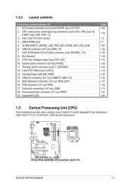
...17 1-21 1-26 1.3 Central Processing Unit (CPU) This motherboard comes with a surface mount LGA1151 socket designed for 6th Generation Intel® Core™ i7 / i5 / i3, Pentium®, and Celeron® processors. B150 PRO GAMING CPU socket LGA1151 ASUS B150 PRO GAMING 1-3 ATX power connectors (24-pin EATXPWR, 8-pin ATX12V) ... Intel® LGA1151 CPU socket 4. Front panel audio connector (10-1 pin AAFP) 19. Intel® B150 Serial ATA 6.0 Gb/s connector (7-pin SATA6G_1~6) 8. 1.2.4 Layout contents Connectors/Jumpers/Slots/LED 1. Q LEDs (BOOT_DEVICE_LED, VGA_LED, DRAM_LED, CPU_LED) 6.
...17 1-21 1-26 1.3 Central Processing Unit (CPU) This motherboard comes with a surface mount LGA1151 socket designed for 6th Generation Intel® Core™ i7 / i5 / i3, Pentium®, and Celeron® processors. B150 PRO GAMING CPU socket LGA1151 ASUS B150 PRO GAMING 1-3 ATX power connectors (24-pin EATXPWR, 8-pin ATX12V) ... Intel® LGA1151 CPU socket 4. Front panel audio connector (10-1 pin AAFP) 19. Intel® B150 Serial ATA 6.0 Gb/s connector (7-pin SATA6G_1~6) 8. 1.2.4 Layout contents Connectors/Jumpers/Slots/LED 1. Q LEDs (BOOT_DEVICE_LED, VGA_LED, DRAM_LED, CPU_LED) 6.

Users manual English
Page 12
... your retailer immediately if the PnP cap is on the socket and the socket contacts are not bent. ASUS will process Return Merchandise Authorization (RMA) requests only if the motherboard comes with the cap on the LGA1151 socket. • The product warranty does not cover damage to the... if you install the correct CPU designed for LGA1150, LGA1155 and LGA1156 sockets on the LGA1151 socket. • Upon purchase of the motherboard, ensure that you see any damage to the socket contacts resulting from incorrect CPU installation/removal, or misplacement/loss/incorrect removal of the PnP...
... your retailer immediately if the PnP cap is on the socket and the socket contacts are not bent. ASUS will process Return Merchandise Authorization (RMA) requests only if the motherboard comes with the cap on the LGA1151 socket. • The product warranty does not cover damage to the... if you install the correct CPU designed for LGA1150, LGA1155 and LGA1156 sockets on the LGA1151 socket. • Upon purchase of the motherboard, ensure that you see any damage to the socket contacts resulting from incorrect CPU installation/removal, or misplacement/loss/incorrect removal of the PnP...

Users manual English
Page 15
... 2 GB, 4 GB, 8 GB, and 16 GB unbuffered non-ECC DDR4 DIMMs into the DIMM sockets. Recommended memory configurations ASUS B150 PRO GAMING 1-7 DO NOT install a DDR, DDR2, or DDR3 memory module to the recommended memory population below. 1.4 System memory 1.4.1 Overview This motherboard comes with four Double Data Rate 4 (DDR4) Dual Inline Memory Module (DIMM) sockets.
... 2 GB, 4 GB, 8 GB, and 16 GB unbuffered non-ECC DDR4 DIMMs into the DIMM sockets. Recommended memory configurations ASUS B150 PRO GAMING 1-7 DO NOT install a DDR, DDR2, or DDR3 memory module to the recommended memory population below. 1.4 System memory 1.4.1 Overview This motherboard comes with four Double Data Rate 4 (DDR4) Dual Inline Memory Module (DIMM) sockets.

Users manual English
Page 16
... Heat-Sink Package N/A Heat-Sink Package Timing 16-18-18-36 - Use a maximum of the following: - For effective use a more on the motherboard, the actual usable memory for the OS can be about 3GB or less. Under the default state, some memory modules for the dual-channel configuration... PANRAM PUD42800C164G4NJW 4G MUSHKIN 994207F 4G KINGSTON HX428C14PBK/32 8G SS/DS SS SS SS SS SS SS SS DS Chip Brand Chip NO. B150 PRO GAMING motherboard memory Qualified Vendors Lists (QVL) DDR4 3000 MHz (O.C.) capability Vendors Part No. To operate at the vendor-marked or at a higher ...
... Heat-Sink Package N/A Heat-Sink Package Timing 16-18-18-36 - Use a maximum of the following: - For effective use a more on the motherboard, the actual usable memory for the OS can be about 3GB or less. Under the default state, some memory modules for the dual-channel configuration... PANRAM PUD42800C164G4NJW 4G MUSHKIN 994207F 4G KINGSTON HX428C14PBK/32 8G SS/DS SS SS SS SS SS SS SS DS Chip Brand Chip NO. B150 PRO GAMING motherboard memory Qualified Vendors Lists (QVL) DDR4 3000 MHz (O.C.) capability Vendors Part No. To operate at the vendor-marked or at a higher ...
Users manual English
Page 20
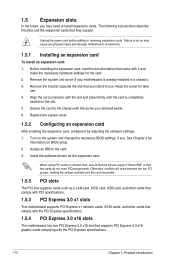
...card is already installed in a chassis). 3. Align the card connector with the PCI Express specifications. 1.5.4 PCI Express 3.0 x16 slots This motherboard has two PCI Express 3.0 x16 slot that they support. Remove the bracket opposite the slot that the cards do so may need IRQ...the card to the card. 3. Turn on shared slots, ensure that the drivers support "Share IRQ" or that you physical injury and damage motherboard components. 1.5.1 Installing an expansion card To install an expansion card: 1. See Chapter 2 for the expansion card. Install the software drivers for information...
...card is already installed in a chassis). 3. Align the card connector with the PCI Express specifications. 1.5.4 PCI Express 3.0 x16 slots This motherboard has two PCI Express 3.0 x16 slot that they support. Remove the bracket opposite the slot that the cards do so may need IRQ...the card to the card. 3. Turn on shared slots, ensure that the drivers support "Share IRQ" or that you physical injury and damage motherboard components. 1.5.1 Installing an expansion card To install an expansion card: 1. See Chapter 2 for the expansion card. Install the software drivers for information...
Users manual English
Page 21
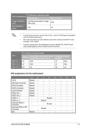
... - - - - - - - Shared - - - - PCIE x1_2 - - Asmedia USB 3.1 Controller - - - ASUS B150 PRO GAMING 1-13 Slot PCIe x1_1 PCIe x1_2 PCIe x16_2 PCI Express operating mode Default Auto (When x4 or faster device is installed on ... Controller Shared - - - - - - - See page 1-23 for details. • Connect a chassis fan to the motherboard connector labeled CHA_FAN1/2/3 when using multiple graphics cards for this motherboard A B C D E F G H I.G.D. PCI Express operating mode VGA configuration PCIe 3.0 x16_1 Single VGA/PCIe x16 (Recommended...
... - - - - - - - Shared - - - - PCIE x1_2 - - Asmedia USB 3.1 Controller - - - ASUS B150 PRO GAMING 1-13 Slot PCIe x1_1 PCIe x1_2 PCIe x16_2 PCI Express operating mode Default Auto (When x4 or faster device is installed on ... Controller Shared - - - - - - - See page 1-23 for details. • Connect a chassis fan to the motherboard connector labeled CHA_FAN1/2/3 when using multiple graphics cards for this motherboard A B C D E F G H I.G.D. PCI Express operating mode VGA configuration PCIe 3.0 x16_1 Single VGA/PCIe x16 (Recommended...
Users manual English
Page 26
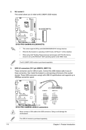
... module to install an M.2 (NGFF) SSD module. M.2(SOCKET3) B150 PRO GAMING M.2(SOCKET3) • This socket supports M Key and 2242/2260/2280/22110 storage devices. • When the M.2 Socket 3 is operating in SATA mode, SATA port 1 will damage the motherboard! Connect the USB module cable to any of the system chassis... USB+5V USB_P11USB_P11+ GND NC USB+5V USB_P9USB_P9+ GND NC USB+5V USB_P12USB_P12+ GND USB+5V USB_P10USB_P10+ GND PIN 1 PIN 1 B150 PRO GAMING USB2.0 connectors Never connect a 1394 cable to 480Mbps connection speed. The USB 2.0 module is purchased separately 3.
... module to install an M.2 (NGFF) SSD module. M.2(SOCKET3) B150 PRO GAMING M.2(SOCKET3) • This socket supports M Key and 2242/2260/2280/22110 storage devices. • When the M.2 Socket 3 is operating in SATA mode, SATA port 1 will damage the motherboard! Connect the USB module cable to any of the system chassis... USB+5V USB_P11USB_P11+ GND NC USB+5V USB_P9USB_P9+ GND NC USB+5V USB_P12USB_P12+ GND USB+5V USB_P10USB_P10+ GND PIN 1 PIN 1 B150 PRO GAMING USB2.0 connectors Never connect a 1394 cable to 480Mbps connection speed. The USB 2.0 module is purchased separately 3.
Users manual English
Page 27
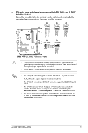
Insufficient air flow inside the system may damage the motherboard components. ASUS B150 PRO GAMING 1-19 To set these fans to DC or PWM, go to Advanced >... CPU fan of maximum 1 A (12 W) fan power. • W_PUMP function support depends on the motherboard, ensuring that the black wire of each cable matches the ground pin of CPU fan installed and automatically switches... GND CHA FAN PWR CHA FAN IN CHA FAN PWM CHA FAN PWM CHA FAN IN CHA FAN PWR GND E B150 PRO GAMING Fan connectors • Do not forget to connect the fan cables to Advanced > Monitor > Q-Fan Configuration > Chassis...
Insufficient air flow inside the system may damage the motherboard components. ASUS B150 PRO GAMING 1-19 To set these fans to DC or PWM, go to Advanced >... CPU fan of maximum 1 A (12 W) fan power. • W_PUMP function support depends on the motherboard, ensuring that the black wire of each cable matches the ground pin of CPU fan installed and automatically switches... GND CHA FAN PWR CHA FAN IN CHA FAN PWM CHA FAN PWM CHA FAN IN CHA FAN PWR GND E B150 PRO GAMING Fan connectors • Do not forget to connect the fan cables to Advanced > Monitor > Q-Fan Configuration > Chassis...
Users manual English
Page 28
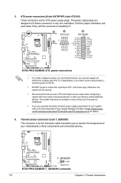
... (2-pin T_SENSOR) This connector is inadequate. • If you to the Recommended Power Supply Wattage Calculator at http://support.asus. The system may become unstable or may not boot up . • We recommend that you use a PSU with higher...motherboard's critical components and connected devices. A A EATX12V B EATXPWR GND GND GND GND PIN 1 B +12V DC +12V DC +12V DC +12V DC +3 Volts +12 Volts +12 Volts +5V Standby Power OK GND +5 Volts GND +5 Volts GND +3 Volts +3 Volts PIN 1 GND +5 Volts +5 Volts +5 Volts -5 Volts GND GND GND PSON# GND -12 Volts +3 Volts B150 PRO GAMING...
... (2-pin T_SENSOR) This connector is inadequate. • If you to the Recommended Power Supply Wattage Calculator at http://support.asus. The system may become unstable or may not boot up . • We recommend that you use a PSU with higher...motherboard's critical components and connected devices. A A EATX12V B EATXPWR GND GND GND GND PIN 1 B +12V DC +12V DC +12V DC +12V DC +3 Volts +12 Volts +12 Volts +5V Standby Power OK GND +5 Volts GND +5 Volts GND +3 Volts +3 Volts PIN 1 GND +5 Volts +5 Volts +5 Volts -5 Volts GND GND GND PSON# GND -12 Volts +3 Volts B150 PRO GAMING...

Users manual English
Page 29
...motherboard's high-definition audio capability. • If you want to connect a high-definition front panel audio module to this connector, set the Front Panel Type item in the BIOS setup to this connector is for the Front Base. See section 2.6.7 Onboard Devices Configuration for more information about the Front Base. ROG_EXT B150 PRO GAMING... ROG_EXT connectors • The Front Base is for a chassis-mounted front panel audio I /O module cable to [HD Audio]. ASUS B150 PRO GAMING 1-21 AAFP HD-audio-compliant pin definition B150 PRO GAMING Front panel ...
...motherboard's high-definition audio capability. • If you want to connect a high-definition front panel audio module to this connector, set the Front Panel Type item in the BIOS setup to this connector is for the Front Base. See section 2.6.7 Onboard Devices Configuration for more information about the Front Base. ROG_EXT B150 PRO GAMING... ROG_EXT connectors • The Front Base is for a chassis-mounted front panel audio I /O module cable to [HD Audio]. ASUS B150 PRO GAMING 1-21 AAFP HD-audio-compliant pin definition B150 PRO GAMING Front panel ...
Users manual English
Page 33
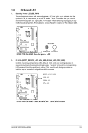
... shut down the system and unplug the power cable before removing or plugging in any motherboard component. SB_PWR ON OFF Standby Power Powered Off B150 PRO GAMING Standby power LED 2. BOOT_DEVICE_LED VGA_LED DRAM_LED CPU_LED B150 PRO GAMING CPU/DRAM/BOOT_DEVICE/VGA LED ASUS B150 PRO GAMING 1-25 Q LEDs (BOOT_DEVICE_LED, VGA_LED, DRAM_LED, CPU_LED) Q LEDs check key components (CPU, DRAM, VGA card, and...
... shut down the system and unplug the power cable before removing or plugging in any motherboard component. SB_PWR ON OFF Standby Power Powered Off B150 PRO GAMING Standby power LED 2. BOOT_DEVICE_LED VGA_LED DRAM_LED CPU_LED B150 PRO GAMING CPU/DRAM/BOOT_DEVICE/VGA LED ASUS B150 PRO GAMING 1-25 Q LEDs (BOOT_DEVICE_LED, VGA_LED, DRAM_LED, CPU_LED) Q LEDs check key components (CPU, DRAM, VGA card, and...
Users manual English
Page 34
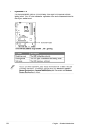
... LED Lighting item. SupremeFX LED B150 PRO GAMING SupremeFX LED Lighting Lit mode Breathing mode Flowing mode Still mode Description The LED blinks intermittently. The LED becomes solid red. See section 2.6.7 Onboard Devices Configuration for details. 1-26 Chapter 1: Product introduction This LED also outlines the separation of your motherboard. You can turn off the...
... LED Lighting item. SupremeFX LED B150 PRO GAMING SupremeFX LED Lighting Lit mode Breathing mode Flowing mode Still mode Description The LED blinks intermittently. The LED becomes solid red. See section 2.6.7 Onboard Devices Configuration for details. 1-26 Chapter 1: Product introduction This LED also outlines the separation of your motherboard. You can turn off the...
Users manual English
Page 35
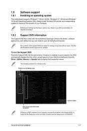
...the Setup.exe to locate the file Setup.exe in your ASUS motherboard. Always install the latest OS version and corresponding updates to display their respective menus. Visit the ASUS website at www.asus.com for detailed information. 1.9.2 Support DVD information The Support ... unique features of the Support DVD are subject to avail all motherboard features. To run the DVD. The following screen is enabled in the root folder. ASUS B150 PRO GAMING 1-27 1.9 Software support 1.9.1 Installing an operating system This motherboard supports Windows® 7 (32-bit / 64-bit), Windows...
...the Setup.exe to locate the file Setup.exe in your ASUS motherboard. Always install the latest OS version and corresponding updates to display their respective menus. Visit the ASUS website at www.asus.com for detailed information. 1.9.2 Support DVD information The Support ... unique features of the Support DVD are subject to avail all motherboard features. To run the DVD. The following screen is enabled in the root folder. ASUS B150 PRO GAMING 1-27 1.9 Software support 1.9.1 Installing an operating system This motherboard supports Windows® 7 (32-bit / 64-bit), Windows...

Users manual English
Page 37
With this utlity, you to automatically update your motherboard's softwares, drivers and the BIOS version easily. Copy the original motherboard BIOS using the ASUS Update utility. 2.1.1 EZ Update EZ Update is a utility that allows you can also manually update the saved ... 2 2.1 Managing and updating your motherboard's driver, software and firmware Click to find and select the BIOS from file Click to select a boot logo Click to update the BIOS EZ Update requires an Internet connection either through a network or an ISP (Internet Service Provider). ASUS B150 PRO GAMING 2-1
With this utlity, you to automatically update your motherboard's softwares, drivers and the BIOS version easily. Copy the original motherboard BIOS using the ASUS Update utility. 2.1.1 EZ Update EZ Update is a utility that allows you can also manually update the saved ... 2 2.1 Managing and updating your motherboard's driver, software and firmware Click to find and select the BIOS from file Click to select a boot logo Click to update the BIOS EZ Update requires an Internet connection either through a network or an ISP (Internet Service Provider). ASUS B150 PRO GAMING 2-1


