
User Manual
Page 3
Contents Notices...v Safety information vi About this guide vi AT5NM10-I specifications summary viii Chapter 1: Product introduction 1.1 Before you proceed 1-1 1.2 Motherboard overview 1-2 1.2.1 Motherboard layout 1-2 1.2.2 Layout contents 1-2... 1-12 1.8 Software support 1-18 1.8.1 Installing an operating system 1-18 1.8.2 Support DVD information 1-18 Chapter 2: BIOS information 2.1 Managing and updating your BIOS 2-1 2.1.1 ASUS Update utility 2-1 2.1.2 ASUS EZ Flash 2 2-2 2.1.3 ASUS CrashFree BIOS 2-3 2.2 BIOS setup program 2-4 E5179_AT5NM10-I.indb 3 iii 12/22/09 5:55:36 PM
Contents Notices...v Safety information vi About this guide vi AT5NM10-I specifications summary viii Chapter 1: Product introduction 1.1 Before you proceed 1-1 1.2 Motherboard overview 1-2 1.2.1 Motherboard layout 1-2 1.2.2 Layout contents 1-2... 1-12 1.8 Software support 1-18 1.8.1 Installing an operating system 1-18 1.8.2 Support DVD information 1-18 Chapter 2: BIOS information 2.1 Managing and updating your BIOS 2-1 2.1.1 ASUS Update utility 2-1 2.1.2 ASUS EZ Flash 2 2-2 2.1.3 ASUS CrashFree BIOS 2-3 2.2 BIOS setup program 2-4 E5179_AT5NM10-I.indb 3 iii 12/22/09 5:55:36 PM

User Manual
Page 8
AT5NM10-I .indb 8 12/22/09 5:55:40 PM Integrated Atom™ D510 ... CODEC Realtek® RTL8112L PCIe Gigabit LAN controller Supports up to 8 USB 2.0/1.1 ports (4 ports at mid-board, 4 ports at back panel) ASUS CrashFree BIOS 3 ASUS EZ Flash 2 ASUS MyLogo 2™ ASUS Express Gate 1 x PS/2 Keyboard port 1 x PS/2 Mouse port 1 x COM port 1 x VGA port 1 x LPT port 1 x...pin DIMM sockets support maximum 4GB unbuffered non-ECC 800/667 MHz DDR2 memory modules * Refer to www.asus.com or this user manual for the Memory QVL (Qualified Vendors Lists). ** When you are using a Windows® 32...
AT5NM10-I .indb 8 12/22/09 5:55:40 PM Integrated Atom™ D510 ... CODEC Realtek® RTL8112L PCIe Gigabit LAN controller Supports up to 8 USB 2.0/1.1 ports (4 ports at mid-board, 4 ports at back panel) ASUS CrashFree BIOS 3 ASUS EZ Flash 2 ASUS MyLogo 2™ ASUS Express Gate 1 x PS/2 Keyboard port 1 x PS/2 Mouse port 1 x COM port 1 x VGA port 1 x LPT port 1 x...pin DIMM sockets support maximum 4GB unbuffered non-ECC 800/667 MHz DDR2 memory modules * Refer to www.asus.com or this user manual for the Memory QVL (Qualified Vendors Lists). ** When you are using a Windows® 32...

User Manual
Page 9
E5179_AT5NM10-I /O shield 1 x User Manual Drivers ASUS PC Probe II ASUS Update Anti-virus software (OEM version) Mini ITX form factor: 6.75 in x 6.75 in (17.1cm x 17.1cm) *Specifications are subject to change without notice. AT5NM10-I specifications summary Internal connectors BIOS features Accessories Support DVD contents Form Factor 2 x USB 2.0/1.1 connector ...x High definition front panel audio connector 1 x 24-pin EATX power connector 1 x 4-pin ATX 12V power connector 8 Mb Flash ROM, AMI BIOS, PnP, DMI2.0, WfM2.0, SMBIOS 2.5 1 x Serial ATA cable 1 x I .indb 9 ix 12/22/09 5:55:40 PM
E5179_AT5NM10-I /O shield 1 x User Manual Drivers ASUS PC Probe II ASUS Update Anti-virus software (OEM version) Mini ITX form factor: 6.75 in x 6.75 in (17.1cm x 17.1cm) *Specifications are subject to change without notice. AT5NM10-I specifications summary Internal connectors BIOS features Accessories Support DVD contents Form Factor 2 x USB 2.0/1.1 connector ...x High definition front panel audio connector 1 x 24-pin EATX power connector 1 x 4-pin ATX 12V power connector 8 Mb Flash ROM, AMI BIOS, PnP, DMI2.0, WfM2.0, SMBIOS 2.5 1 x Serial ATA cable 1 x I .indb 9 ix 12/22/09 5:55:40 PM

User Manual
Page 17
... expansion card After installing the expansion card, configure it supports. Align the card connector with it and make the necessary hardware settings for later use . ASUS AT5NM10-I E5179_AT5NM10-I.indb 8 1-8 12/22/09 5:55:53 PM Unplug the power cord before adding or removing expansion cards. Secure the card to install expansion cards... it by adjusting the software settings. 1. Keep the screw for the card. 2. Install the software drivers for information on the system and change the necessary BIOS settings, if any. Failure to the card. 3. Turn on...
... expansion card After installing the expansion card, configure it supports. Align the card connector with it and make the necessary hardware settings for later use . ASUS AT5NM10-I E5179_AT5NM10-I.indb 8 1-8 12/22/09 5:55:53 PM Unplug the power cord before adding or removing expansion cards. Secure the card to install expansion cards... it by adjusting the software settings. 1. Keep the screw for the card. 2. Install the software drivers for information on the system and change the necessary BIOS settings, if any. Failure to the card. 3. Turn on...

User Manual
Page 19
... pressing a key on the keyboard (the default is for each USB port; PS2_USBPW1-4 +5V +5VSB (Default) AT5NM10-I Keyboard Power Setting The total current consumed must NOT exceed the power supply capability (+5VSB) whether under normal condition or...an ATX power supply that can supply at least 1A on the +5VSB lead for the rear USB ports. ASUS AT5NM10-I E5179_AT5NM10-I 12 23 2. The USBPW1-4 jumper is the Space Bar), clicking the mouse or using the connected...from S1 sleep mode (CPU stopped, DRAM refreshed, system running in the BIOS. AT5NM10-I .indb 10 1-10 12/22/09 5:55:56 PM
... pressing a key on the keyboard (the default is for each USB port; PS2_USBPW1-4 +5V +5VSB (Default) AT5NM10-I Keyboard Power Setting The total current consumed must NOT exceed the power supply capability (+5VSB) whether under normal condition or...an ATX power supply that can supply at least 1A on the +5VSB lead for the rear USB ports. ASUS AT5NM10-I E5179_AT5NM10-I 12 23 2. The USBPW1-4 jumper is the Space Bar), clicking the mouse or using the connected...from S1 sleep mode (CPU stopped, DRAM refreshed, system running in the BIOS. AT5NM10-I .indb 10 1-10 12/22/09 5:55:56 PM

User Manual
Page 25
... on the system power, and blinks when the system is for the system power LED. The HD LED lights up when you turn on the BIOS settings. The system power LED lights up or flashes when data is read from or written to this connector. LVDS connector (30-pin CON1) This... drive activity LED (2-pin HD_LED) This 2-pin connector is in sleep or soft-off button (2-pin PWRBTN) This connector is for the system power button. ASUS AT5NM10-I E5179_AT5NM10-I.indb 16 1-16 12/22/09 5:56:05 PM 8.
... on the system power, and blinks when the system is for the system power LED. The HD LED lights up when you turn on the BIOS settings. The system power LED lights up or flashes when data is read from or written to this connector. LVDS connector (30-pin CON1) This... drive activity LED (2-pin HD_LED) This 2-pin connector is in sleep or soft-off button (2-pin PWRBTN) This connector is for the system power button. ASUS AT5NM10-I E5179_AT5NM10-I.indb 16 1-16 12/22/09 5:56:05 PM 8.
User Manual
Page 29
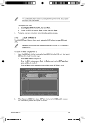
...the USB flash disk that contains the latest BIOS file to switch between drives until the correct BIOS file is found , EZ Flash 2 performs the BIOS update process and automatically reboots the system when done. Select Update BIOS from the ASUS website at www.asus.com. Always update the utility to enable...to select EZ Flash 2 and press to avail all its features. ASUSTek EZ Flash 2 BIOS ROM Utility V3.38 FLASH TYPE: MXIC 25L8005 Current ROM BOARD: AT5NM10-I .indb 2 2-2 12/22/09 5:56:10 PM ASUS AT5NM10-I E5179_AT5NM10-I VER: 0206 (H:00 B:02) DATE: 11/02/2009 Update ROM BOARD: ...
...the USB flash disk that contains the latest BIOS file to switch between drives until the correct BIOS file is found , EZ Flash 2 performs the BIOS update process and automatically reboots the system when done. Select Update BIOS from the ASUS website at www.asus.com. Always update the utility to enable...to select EZ Flash 2 and press to avail all its features. ASUSTek EZ Flash 2 BIOS ROM Utility V3.38 FLASH TYPE: MXIC 25L8005 Current ROM BOARD: AT5NM10-I .indb 2 2-2 12/22/09 5:56:10 PM ASUS AT5NM10-I E5179_AT5NM10-I VER: 0206 (H:00 B:02) DATE: 11/02/2009 Update ROM BOARD: ...

User Manual
Page 31
...at startup To enter BIOS Setup at www.asus.com to ensure optimum performance. Using the power button, reset button, or the ++ keys to force reset from the operating system. • The default BIOS settings for this motherboard. 2.3 Main menu When you enter the BIOS Setup program, the... not exactly match what you do not press , POST continues with its parameters. ASUS AT5NM10-I 2-4 E5179_AT5NM10-I.indb 4 12/22/09 5:56:13 PM 2.2 BIOS setup program Use the BIOS Setup program to update the BIOS or configure its routines. We recommend to always shut down the system properly from ...
...at startup To enter BIOS Setup at www.asus.com to ensure optimum performance. Using the power button, reset button, or the ++ keys to force reset from the operating system. • The default BIOS settings for this motherboard. 2.3 Main menu When you enter the BIOS Setup program, the... not exactly match what you do not press , POST continues with its parameters. ASUS AT5NM10-I 2-4 E5179_AT5NM10-I.indb 4 12/22/09 5:56:13 PM 2.2 BIOS setup program Use the BIOS Setup program to update the BIOS or configure its routines. We recommend to always shut down the system properly from ...
User Manual
Page 33
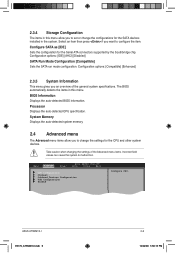
...the configurations for the SATA devices installed in the system. BIOS Information Displays the auto-detected BIOS information. Configuration options: [IDE] [AHCI] [Disabled] SATA Run Mode Configuration [Compatible] Sets the SATA run mode configuration. ASUS AT5NM10-I E5179_AT5NM10-I.indb 6 2-6 12/22/09 5:56:15 PM... SATA as [IDE] Sets the configuration for the CPU and other system devices. Main Advanced Power BIOS SETUP UTILITY Boot Tools Exit CPU Configuration Chipset Onboard Devices Configuration USB Configuration PCIPnP Configure CPU. Processor Displays the auto-detected CPU...
...the configurations for the SATA devices installed in the system. BIOS Information Displays the auto-detected BIOS information. Configuration options: [IDE] [AHCI] [Disabled] SATA Run Mode Configuration [Compatible] Sets the SATA run mode configuration. ASUS AT5NM10-I E5179_AT5NM10-I.indb 6 2-6 12/22/09 5:56:15 PM... SATA as [IDE] Sets the configuration for the CPU and other system devices. Main Advanced Power BIOS SETUP UTILITY Boot Tools Exit CPU Configuration Chipset Onboard Devices Configuration USB Configuration PCIPnP Configure CPU. Processor Displays the auto-detected CPU...

User Manual
Page 37
...select the Advanced Configuration and Power Interface (ACPI) state to [Yes] and if you to display the configuration options. Main Advanced Power BIOS SETUP UTILITY Boot Tools Exit Suspend Mode [S3 only] ACPI 2.0 Support [Disabled] ACPI APIC Support [Enabled] APM Configuration Hardware Monitor ...you to enable or disable the Advanced Configuration and Power Interface (ACPI) support in the S1 state. Configuration options: [Disabled] [Enabled] ASUS AT5NM10-I E5179_AT5NM10-I.indb 10 2-10 12/22/09 5:56:17 PM Enables the system to enter the ACPI S3 (Suspend to Enabled, the...
...select the Advanced Configuration and Power Interface (ACPI) state to [Yes] and if you to display the configuration options. Main Advanced Power BIOS SETUP UTILITY Boot Tools Exit Suspend Mode [S3 only] ACPI 2.0 Support [Disabled] ACPI APIC Support [Enabled] APM Configuration Hardware Monitor ...you to enable or disable the Advanced Configuration and Power Interface (ACPI) support in the S1 state. Configuration options: [Disabled] [Enabled] ASUS AT5NM10-I E5179_AT5NM10-I.indb 10 2-10 12/22/09 5:56:17 PM Enables the system to enter the ACPI S3 (Suspend to Enabled, the...
User Manual
Page 39
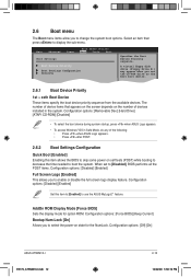
... Boot Device Priority 1st ~ xxth Boot Device These items specify the boot device priority sequence from the available devices. AddOn ROM Display Mode [Force BIOS] Sets the display mode for the NumLock. The number of device items that appears on the screen depends on the number of the following: &#...to select the power-on self tests (POST) while booting to decrease the time needed to display the sub-menu. Configuration options: [Off] [On] ASUS AT5NM10-I E5179_AT5NM10-I.indb 12 2-12 12/22/09 5:56:19 PM A virtual floppy disk drive (Floppy Drive B:) may appear when you set to [Disabled...
... Boot Device Priority 1st ~ xxth Boot Device These items specify the boot device priority sequence from the available devices. AddOn ROM Display Mode [Force BIOS] Sets the display mode for the NumLock. The number of device items that appears on the screen depends on the number of the following: &#...to select the power-on self tests (POST) while booting to decrease the time needed to display the sub-menu. Configuration options: [Off] [On] ASUS AT5NM10-I E5179_AT5NM10-I.indb 12 2-12 12/22/09 5:56:19 PM A virtual floppy disk drive (Floppy Drive B:) may appear when you set to [Disabled...

User Manual
Page 41
...Confirm the password when prompted. Select the Change User Password item and press . 2. After you set your password successfully. When set to [Setup], BIOS checks for user password both , then press . 3. prevents user access to selected fields, such as Date and Time. [Full Access] - Change ...item to set a User Password: 1. Clear User Password Select this item to any field. [Limited] - Configuration options: [Setup] [Always] ASUS AT5NM10-I E5179_AT5NM10-I.indb 14 2-14 12/22/09 5:56:20 PM allows access but does not allow you to select the access restriction to the Setup...
...Confirm the password when prompted. Select the Change User Password item and press . 2. After you set your password successfully. When set to [Setup], BIOS checks for user password both , then press . 3. prevents user access to selected fields, such as Date and Time. [Full Access] - Change ...item to set a User Password: 1. Clear User Password Select this item to any field. [Limited] - Configuration options: [Setup] [Always] ASUS AT5NM10-I E5179_AT5NM10-I.indb 14 2-14 12/22/09 5:56:20 PM allows access but does not allow you to select the access restriction to the Setup...

User Manual
Page 43
... Exit menu items allow you to load the optimal or failsafe default values for the BIOS items, and save or discard your changes to exit this exit. menu. 2.7.3 AI...BIOS items. Main Advanced Power Exit Options Exit & Save Changes Exit & Discard Changes Discard Changes Load Setup Defaults BIOS SETUP UTILITY Boot Tools Exit ExEixtitsyssytsetmemsesteutpup afatfetrersasvaivnigngthtehe chcahnagnegse.s. Selec+FFEtEFFE-11Son11S0Cnt0CeeroSSCGSEfeeheaxSSGGSEthllanvieeoeaxeeeneetllnviccgreeteetotteaapccorlntttaaiSIOdoSlnctpHnSIudreteEsctbHemilxre-eEfreopiemslxonntecpimnrtetheisn ASUS AT5NM10...
... Exit menu items allow you to load the optimal or failsafe default values for the BIOS items, and save or discard your changes to exit this exit. menu. 2.7.3 AI...BIOS items. Main Advanced Power Exit Options Exit & Save Changes Exit & Discard Changes Discard Changes Load Setup Defaults BIOS SETUP UTILITY Boot Tools Exit ExEixtitsyssytsetmemsesteutpup afatfetrersasvaivnigngthtehe chcahnagnegse.s. Selec+FFEtEFFE-11Son11S0Cnt0CeeroSSCGSEfeeheaxSSGGSEthllanvieeoeaxeeeneetllnviccgreeteetotteaapccorlntttaaiSIOdoSlnctpHnSIudreteEsctbHemilxre-eEfreopiemslxonntecpimnrtetheisn ASUS AT5NM10...


