
User Guide
Page 3
Contents Notices ...vi Safety information vii A8N-SLI specifications summary viii Chapter 1: Hardware information 1 . 1 Before you proceed 1 - 2 1 . 2 Motherboard overview 1 - 3 1.2.1 Placement direction 1 - 3 1.2.2 Screw holes 1 - 3 1.2.3 Motherboard layout 1 - 4 1.2.4 Layout contents 1 - 5 1 . 3 Central Processing Unit (CPU 1 - 7 1.3.1 Installing the CPU 1 - 7 1.3.2 Installing the heatsink and fan 1 - 9 1 . 4 System memory 1 - 1 2 1.4.1 Overview 1 - 1 2 1.4.2 Memory configurations 1 - 1 2 1.4.3 Installing a DIMM 1 - 1 3 1.4.4 Removing a DIMM 1 - 1 3 1 . 5 Expansion slots 1 -...
Contents Notices ...vi Safety information vii A8N-SLI specifications summary viii Chapter 1: Hardware information 1 . 1 Before you proceed 1 - 2 1 . 2 Motherboard overview 1 - 3 1.2.1 Placement direction 1 - 3 1.2.2 Screw holes 1 - 3 1.2.3 Motherboard layout 1 - 4 1.2.4 Layout contents 1 - 5 1 . 3 Central Processing Unit (CPU 1 - 7 1.3.1 Installing the CPU 1 - 7 1.3.2 Installing the heatsink and fan 1 - 9 1 . 4 System memory 1 - 1 2 1.4.1 Overview 1 - 1 2 1.4.2 Memory configurations 1 - 1 2 1.4.3 Installing a DIMM 1 - 1 3 1.4.4 Removing a DIMM 1 - 1 3 1 . 5 Expansion slots 1 -...

User Guide
Page 4
... program 2 - 8 2.2.1 BIOS menu bar 2 - 9 2.2.2 Legend bar 2 - 9 2 . 3 Main Menu 2 - 1 1 2.3.1 System Time 2 - 1 1 2.3.2 System Date 2 - 1 1 2.3.3 Legacy Diskette A 2 - 1 1 2.3.4 Installed Memory 2 - 1 1 2.3.5 Primary and Secondary IDE Master/Slave 2 - 1 2 2.3.6 First, Second, Third, and Fourth SATA Master ..... 2 - 1 4 2.3.7 Installed Memory 2 - 1 5 2 . 4 Advanced Menu 2 - 1 6 2.4.1 CPU configuration 2 - 1 7 2.4.2 Chipset configuration 2 - 1 8 2.4.3 PCIPnP 2 - 2 0 2.4.4 Onboard device configuration 2 - 2 2 2 . 5 Power Menu 2 - 2 8 2.5.1 APM configuration 2 - 2 9 2.5.2 Hardware...
... program 2 - 8 2.2.1 BIOS menu bar 2 - 9 2.2.2 Legend bar 2 - 9 2 . 3 Main Menu 2 - 1 1 2.3.1 System Time 2 - 1 1 2.3.2 System Date 2 - 1 1 2.3.3 Legacy Diskette A 2 - 1 1 2.3.4 Installed Memory 2 - 1 1 2.3.5 Primary and Secondary IDE Master/Slave 2 - 1 2 2.3.6 First, Second, Third, and Fourth SATA Master ..... 2 - 1 4 2.3.7 Installed Memory 2 - 1 5 2 . 4 Advanced Menu 2 - 1 6 2.4.1 CPU configuration 2 - 1 7 2.4.2 Chipset configuration 2 - 1 8 2.4.3 PCIPnP 2 - 2 0 2.4.4 Onboard device configuration 2 - 2 2 2 . 5 Power Menu 2 - 2 8 2.5.1 APM configuration 2 - 2 9 2.5.2 Hardware...

User Guide
Page 8
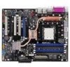
... 1394 USB BIOS features Special features Socket 939 for AMD Athlon™ 64FX/AMD Athlon™ 64 processor Supports AMD 64 architecture that enables simultaneous 32-bit and 64-bit architecture NVIDIA® nForce™4 SLI 1 GHz (K8) / 800 MHz Dual-channel memory architecture 4 x 184-pin DIMM sockets support non-ECC unbufferred 400 MHz DDR memory modules Supports up to 2 GB...
... 1394 USB BIOS features Special features Socket 939 for AMD Athlon™ 64FX/AMD Athlon™ 64 processor Supports AMD 64 architecture that enables simultaneous 32-bit and 64-bit architecture NVIDIA® nForce™4 SLI 1 GHz (K8) / 800 MHz Dual-channel memory architecture 4 x 184-pin DIMM sockets support non-ECC unbufferred 400 MHz DDR memory modules Supports up to 2 GB...

User Guide
Page 22
...) Dual Inline Memory Modules (DIMM) sockets. The following figure illustrates the location of the sockets: DIMM_A1 DIMM_A2 DIMM_B1 DIMM_B2 A8N-SLI ® A8N-SLI 184-pin DDR DIMM sockets Channel Channel A Channel B Sockets DIMM_A1 and DIMM_A2 DIMM_B1 and DIMM_B2 1 . 4 . 2 Memory configurations You may... DDR DIMMs into the DIMM sockets using the memory configurations in this motherboard does not support DIMM modules with 128 Mb memory chips or double-sided x16 memory chips. 1-12 Chapter 1: Hardware information 1.4 System memory 1.4.1 Overview The motherboard comes with the same CAS ...
...) Dual Inline Memory Modules (DIMM) sockets. The following figure illustrates the location of the sockets: DIMM_A1 DIMM_A2 DIMM_B1 DIMM_B2 A8N-SLI ® A8N-SLI 184-pin DDR DIMM sockets Channel Channel A Channel B Sockets DIMM_A1 and DIMM_A2 DIMM_B1 and DIMM_B2 1 . 4 . 2 Memory configurations You may... DDR DIMMs into the DIMM sockets using the memory configurations in this motherboard does not support DIMM modules with 128 Mb memory chips or double-sided x16 memory chips. 1-12 Chapter 1: Hardware information 1.4 System memory 1.4.1 Overview The motherboard comes with the same CAS ...
User Guide
Page 27
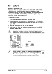
... to default values. The onboard button cell battery powers the RAM data in CMOS. Move the jumper cap from pins 1-2 (default) to re-enter data. ASUS A8N-SLI 1-17 Turn OFF the computer and unplug the power cord. 2 . Plug the power cord and turn ON the computer. 4 . Except when clearing the ... RAM in CMOS, which include system setup information such as system passwords. Hold down and reboot the system so the BIOS can clear the CMOS memory of date, time, and system setup parameters by erasing the CMOS RTC RAM data. For system failure due to overclocking. Removing the cap will cause...
... to default values. The onboard button cell battery powers the RAM data in CMOS. Move the jumper cap from pins 1-2 (default) to re-enter data. ASUS A8N-SLI 1-17 Turn OFF the computer and unplug the power cord. 2 . Plug the power cord and turn ON the computer. 4 . Except when clearing the ... RAM in CMOS, which include system setup information such as system passwords. Hold down and reboot the system so the BIOS can clear the CMOS memory of date, time, and system setup parameters by erasing the CMOS RTC RAM data. For system failure due to overclocking. Removing the cap will cause...

User Guide
Page 41
... Copy the original or the latest motherboard BIOS file to the bootable floppy disk. 2 . 1 . 2 AwardBIOS Flash Utility The Basic Input/Output System (BIOS) can be updated using this utility. Follow these instructions to the floppy disk with the executable Flash Memory Writer Utility (AWDFLASH.EXE). Copy the...Insert the Windows® 2000 CD to continue. 2 . c. Click Start, then select Run. Save only the updated BIOS file in Flash Memory Writer utility or using the bootable floppy disk you created earlier. Updating the BIOS file 1 . Rename the file to (BIOS file name on...
... Copy the original or the latest motherboard BIOS file to the bootable floppy disk. 2 . 1 . 2 AwardBIOS Flash Utility The Basic Input/Output System (BIOS) can be updated using this utility. Follow these instructions to the floppy disk with the executable Flash Memory Writer Utility (AWDFLASH.EXE). Copy the...Insert the Windows® 2000 CD to continue. 2 . c. Click Start, then select Run. Save only the updated BIOS file in Flash Memory Writer utility or using the bootable floppy disk you created earlier. Updating the BIOS file 1 . Rename the file to (BIOS file name on...

User Guide
Page 49
... 5.25 in.] [720K , 3.5 in.] [1.44M, 3.5 in.] [2.88M, 3.5 in.] 2 . 3 . 4 Installed Memory [xxxMB] This field automatically displays the amount of floppy drive installed. The format is hour, minute, second. 2.3 Main Menu ...between the month, day, and year fields. 2 . 3 . 3 Legacy Diskette A [1.44M, 3.5 in .] [ST320410A] [ASUS CD--S520/] [None] [None] [None] [None] [None] [None] 256MB Select Menu Item Specific Help Change the internal ... Master Fourth SATA Master Installed Memory 17:8:12 Thu, Mar 17 2005 [1.44M, 3.5 in .] Sets the type of conventional memory detected by the system during ...
... 5.25 in.] [720K , 3.5 in.] [1.44M, 3.5 in.] [2.88M, 3.5 in.] 2 . 3 . 4 Installed Memory [xxxMB] This field automatically displays the amount of floppy drive installed. The format is hour, minute, second. 2.3 Main Menu ...between the month, day, and year fields. 2 . 3 . 3 Legacy Diskette A [1.44M, 3.5 in .] [ST320410A] [ASUS CD--S520/] [None] [None] [None] [None] [None] [None] 256MB Select Menu Item Specific Help Change the internal ... Master Fourth SATA Master Installed Memory 17:8:12 Thu, Mar 17 2005 [1.44M, 3.5 in .] Sets the type of conventional memory detected by the system during ...

User Guide
Page 53
... the partition of the Primary IDE hard disk drives to partition and format new IDE hard disk drives. Sector Shows the number of installed memory. ASUS A8N-SLI 2-15 Head Shows the number of landing zone per track. This item is not configurable. This is not configurable. This item is necessary... item is not configurable. After entering the IDE hard disk drive information into BIOS, use a disk utility, such as FDISK, to active. 2 . 3 . 7 Installed Memory Shows the size of sectors per track. Landing Zone Shows the number of the hard disk read data from the hard disk.
... the partition of the Primary IDE hard disk drives to partition and format new IDE hard disk drives. Sector Shows the number of installed memory. ASUS A8N-SLI 2-15 Head Shows the number of landing zone per track. This item is not configurable. This is not configurable. This item is necessary... item is not configurable. After entering the IDE hard disk drive information into BIOS, use a disk utility, such as FDISK, to active. 2 . 3 . 7 Installed Memory Shows the size of sectors per track. Landing Zone Shows the number of the hard disk read data from the hard disk.
User Guide
Page 56
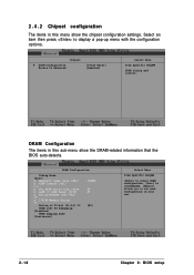
... Mode [Auto] x Memclock index value (Mhz) x CAS# Latency (Tcl) 2.5 x Min RAS# active time (Tras) x RAS# to CAS# delay (Trcd) x Row precharge time (Trp) 2T x 1/T/2T Memory Timing 2T Bottom of 32-bit [31:24] IO DRAM Over 4G Remapping [Disabled] MTRR mapping mode [Continuous] 200Mhz 8T 4T [E0] Select Menu Item...
... Mode [Auto] x Memclock index value (Mhz) x CAS# Latency (Tcl) 2.5 x Min RAS# active time (Tras) x RAS# to CAS# delay (Trcd) x Row precharge time (Trp) 2T x 1/T/2T Memory Timing 2T Bottom of 32-bit [31:24] IO DRAM Over 4G Remapping [Disabled] MTRR mapping mode [Continuous] 200Mhz 8T 4T [E0] Select Menu Item...

User Guide
Page 57
... [133Mhz] [166Mhz] [200Mhz] CAS# latency (Tcl) [2.5] Sets the CAS# latency. Configuration options: [2T] ~ [7T] 1T/2T Memory Timing [2T] Sets the memory timing. Timing Mode [Auto] Sets the timing mode. Configuration options: [5T] ~ [15T] RAS# to CAS# delay (Trcd) [4T]...the 32-bit memory-mapped IO location. Configuration options: [2] [2.5] [3] Min RAS# active time (Tras) [8T] Sets the minimum RAS# active time. Configuration options: [2T] ~ [7T] Row precharge Time (Trp) [2T] Sets the Row precharge time. Configuration options: [Disabled] [Enabled] ASUS A8N-SLI 2-19 Configuration ...
... [133Mhz] [166Mhz] [200Mhz] CAS# latency (Tcl) [2.5] Sets the CAS# latency. Configuration options: [2T] ~ [7T] 1T/2T Memory Timing [2T] Sets the memory timing. Timing Mode [Auto] Sets the timing mode. Configuration options: [5T] ~ [15T] RAS# to CAS# delay (Trcd) [4T]...the 32-bit memory-mapped IO location. Configuration options: [2] [2.5] [3] Min RAS# active time (Tras) [8T] Sets the minimum RAS# active time. Configuration options: [2T] ~ [7T] Row precharge Time (Trp) [2T] Sets the Row precharge time. Configuration options: [Disabled] [Enabled] ASUS A8N-SLI 2-19 Configuration ...


