
User Manual
Page 50
A ribbon cable attaches to the CD-ROM adapter board and plugs into place. To open the tray, press the button in the middle and carefully pull open the tray until it lightly clicks. To close the drive, push the tray until it is completely closed and locked into connector J14 on the front of the CD-ROM module and should not be removed or replaced. Basics CD-ROM Drive - 34 CD-ROM Drive The CD-ROM drive is located beneath the screen on the logic board. The CD adapter board is part of the iMac. CD Adapter Board The CD adapter board screws onto the back of the CD-ROM drive.
A ribbon cable attaches to the CD-ROM adapter board and plugs into place. To open the tray, press the button in the middle and carefully pull open the tray until it lightly clicks. To close the drive, push the tray until it is completely closed and locked into connector J14 on the front of the CD-ROM module and should not be removed or replaced. Basics CD-ROM Drive - 34 CD-ROM Drive The CD-ROM drive is located beneath the screen on the logic board. The CD adapter board is part of the iMac. CD Adapter Board The CD adapter board screws onto the back of the CD-ROM drive.

User Manual
Page 95
...originate at the internal microphone, they travel along the long internal audio cable to the microphone (sound in signals travel through the iMac. If the sound signals originate at an external microphone, they are transmitted to see an animation of how the sound in )... interconnect board, travels via the internal RGB cable to connector J2 on the A/V interconnect board. From there, the signals are displayed on the screen. The video signals then travel out from the external microphone to connector J6 on the A/V interconnect board. Troubleshooting General/ Video Flow - 1 ...
...originate at the internal microphone, they travel along the long internal audio cable to the microphone (sound in signals travel through the iMac. If the sound signals originate at an external microphone, they are transmitted to see an animation of how the sound in )... interconnect board, travels via the internal RGB cable to connector J2 on the A/V interconnect board. From there, the signals are displayed on the screen. The video signals then travel out from the external microphone to connector J6 on the A/V interconnect board. Troubleshooting General/ Video Flow - 1 ...

User Manual
Page 99
Because cures are listed on the charts in the order of the computer. No LED, no fan, no hard drive power, and the screen is connected properly to the computer.Disconnect the keyboard and power on the system via the button on the logic board. No Power 1 Refer ... whether or not the product continues to determine if the existing power cord could be the problem. 3 Possible bad USB keyboard. For additional assistance, contact Apple Technical Support. Is there +5V power? - Troubleshooting Symptom Charts/ How to Use the Symptom Charts - 1 7 Symptom Charts How to Use the Symptom Charts ...
Because cures are listed on the charts in the order of the computer. No LED, no fan, no hard drive power, and the screen is connected properly to the computer.Disconnect the keyboard and power on the system via the button on the logic board. No Power 1 Refer ... whether or not the product continues to determine if the existing power cord could be the problem. 3 Possible bad USB keyboard. For additional assistance, contact Apple Technical Support. Is there +5V power? - Troubleshooting Symptom Charts/ How to Use the Symptom Charts - 1 7 Symptom Charts How to Use the Symptom Charts ...

User Manual
Page 100
Video Problems No video, the screen is evidenced by an illuminated amber LED, and a running fan. 1. No: Follow these steps to next step. Replace the logic board. 4 Verify that the following ...
Video Problems No video, the screen is evidenced by an illuminated amber LED, and a running fan. 1. No: Follow these steps to next step. Replace the logic board. 4 Verify that the following ...

User Manual
Page 101
...cable that attaches to the logic board at J16 and the A/V interconnect board at J2. • Internal RGB cable that came with the appropriate iMac enablers.) No: Go to next step. 4 Reseat the internal RGB cable that attaches to the logic board at J16 and the A/V interconnect board...internal video cable that the following cables are two versions of Mac OS with the unit. Do you see a normal screen display now? Troubleshooting Symptom Charts/ Video Problems - 1 9 Solid gray screen, however, normal startup boot chime, power LED on, and the fan is running. 1 Reset parameter RAM. If the...
...cable that attaches to the logic board at J16 and the A/V interconnect board at J2. • Internal RGB cable that came with the appropriate iMac enablers.) No: Go to next step. 4 Reseat the internal RGB cable that attaches to the logic board at J16 and the A/V interconnect board...internal video cable that the following cables are two versions of Mac OS with the unit. Do you see a normal screen display now? Troubleshooting Symptom Charts/ Video Problems - 1 9 Solid gray screen, however, normal startup boot chime, power LED on, and the fan is running. 1 Reset parameter RAM. If the...

User Manual
Page 102
... using the Display Adjustment Utility on the MacTest Pro CD. (See "Focus" in the iMac Adjustments chapter for instructions.) 2 Adjust the screen geometry using the Display Adjustment Utility on the MacTest Pro CD. (See "Geometry" in the iMac Adjustments chapter for instructions.) 3 Adjust the cutoff or white balance using the Display Adjustment and...
... using the Display Adjustment Utility on the MacTest Pro CD. (See "Focus" in the iMac Adjustments chapter for instructions.) 2 Adjust the screen geometry using the Display Adjustment Utility on the MacTest Pro CD. (See "Geometry" in the iMac Adjustments chapter for instructions.) 3 Adjust the cutoff or white balance using the Display Adjustment and...

User Manual
Page 103
.... Troubleshooting Symptom Charts/ Video Problems - 2 1 A predominant color tint or color covering the screen. 1 Verify that the iMac unit is not firmly seated, pushing on the CD-ROM drive can move the iMac computer to another area and restart the unit. 2 Reseat the video cable connecting from the interconnect...that runs between J5 on the A/V interconnect board and at P301 on the screen 1 Boot off the system CD that could affect the video display. Yes: Replace the existing VRAM DIMMs with the appropriate iMac enablers.) No: Go to logic board video cable routes behind the CD-ROM...
.... Troubleshooting Symptom Charts/ Video Problems - 2 1 A predominant color tint or color covering the screen. 1 Verify that the iMac unit is not firmly seated, pushing on the CD-ROM drive can move the iMac computer to another area and restart the unit. 2 Reseat the video cable connecting from the interconnect...that runs between J5 on the A/V interconnect board and at P301 on the screen 1 Boot off the system CD that could affect the video display. Yes: Replace the existing VRAM DIMMs with the appropriate iMac enablers.) No: Go to logic board video cable routes behind the CD-ROM...

User Manual
Page 105
...are most likely the problem. Check all data on the hard drive when you have a successful startup sequence A flashing question mark appears on the desktop? Replace the hard drive. - Troubleshooting Symptom Charts/ Memory Error Dialog Box - 23 Memory Error Dialog Box An error dialog message appears pertaining ... hard drive power cable. 3 Replace the logic board. Yes: Use Drive Setup 1.5.1 to next step. 2 If you see the hard drive on the screen during startup. Backup the data first if possible. - Replace the SDRAM with a known-good SO-DIMM. Replace the hard drive/CD data cable. - ...
...are most likely the problem. Check all data on the hard drive when you have a successful startup sequence A flashing question mark appears on the desktop? Replace the hard drive. - Troubleshooting Symptom Charts/ Memory Error Dialog Box - 23 Memory Error Dialog Box An error dialog message appears pertaining ... hard drive power cable. 3 Replace the logic board. Yes: Use Drive Setup 1.5.1 to next step. 2 If you see the hard drive on the screen during startup. Backup the data first if possible. - Replace the SDRAM with a known-good SO-DIMM. Replace the hard drive/CD data cable. - ...

User Manual
Page 106
... keyboard. Troubleshooting Symptom Charts/ Can't Wake From Sleep - 2 4 Can't Wake From Sleep Computer cannot be brought out of Mac OS. 3 Reset the PRAM by a black screen and a Green or Amber LED. 1 Is the front LED green? P-and R keys.
... keyboard. Troubleshooting Symptom Charts/ Can't Wake From Sleep - 2 4 Can't Wake From Sleep Computer cannot be brought out of Mac OS. 3 Reset the PRAM by a black screen and a Green or Amber LED. 1 Is the front LED green? P-and R keys.

User Manual
Page 115
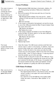
In the Device screen, the USB version number in the upper left corner should be greater than 1.0 - Under the name, it should be "iMac Update 1.0" or greater. The iMac Update 1.0 software is connected to. Run Apple System Profiler. Refer to TIL #44005 for additional information. 2 Not enough power... source, or not enough power available from the hub the device is available at all due to a lack of power. Apple recommends every iMac customer install this error message indicates a device may occur with many USB peripherals. Similar to the first error message, this update...
In the Device screen, the USB version number in the upper left corner should be greater than 1.0 - Under the name, it should be "iMac Update 1.0" or greater. The iMac Update 1.0 software is connected to. Run Apple System Profiler. Refer to TIL #44005 for additional information. 2 Not enough power... source, or not enough power available from the hub the device is available at all due to a lack of power. Apple recommends every iMac customer install this error message indicates a device may occur with many USB peripherals. Similar to the first error message, this update...
User Manual
Page 117
... loses its ability to track in one of the mouse, it to the other USB port. Yes: Replace the keyboard. Refer to an attached, knowngood USB printer. 1 Does the unit have the iMac Update 1.0? Run Apple System Profiler. Yes: Reinstall system software.... (You must remain clean in the upper left corner should be greater than 1.0 - No: Replace the mouse. 4 If the mouse is already connected to one direction. 1 Clean the mouse. In addition, there are dirty the USB mouse may need to be replaced. In the Device screen...
... loses its ability to track in one of the mouse, it to the other USB port. Yes: Replace the keyboard. Refer to an attached, knowngood USB printer. 1 Does the unit have the iMac Update 1.0? Run Apple System Profiler. Yes: Reinstall system software.... (You must remain clean in the upper left corner should be greater than 1.0 - No: Replace the mouse. 4 If the mouse is already connected to one direction. 1 Clean the mouse. In addition, there are dirty the USB mouse may need to be replaced. In the Device screen...

User Manual
Page 121
... Earthlink setup screen) the sound is On, and the dialing is set to Tone. If the problem persists, reinstall the system software. Troubleshooting Symptom Charts/ Modem Dialing Problems - 39 Modem Cannot Dial Out 1 Open the modem control panel and make sure the modem type selected is iMac Internal 56K, (or Apple iMac internal modem...
... Earthlink setup screen) the sound is On, and the dialing is set to Tone. If the problem persists, reinstall the system software. Troubleshooting Symptom Charts/ Modem Dialing Problems - 39 Modem Cannot Dial Out 1 Open the modem control panel and make sure the modem type selected is iMac Internal 56K, (or Apple iMac internal modem...

User Manual
Page 271
Note: When the light meter is not in its protective case. Place the lens against the middle of the screen and read the bottom scale. Set the scale switch to the bottom position (to its top position, and store the meter in use, slide the scale switch to set up the 10-50 fc scale). 2. Adjustments Adjustment Tools - 4 To measure a display screen's luminance, 1.
Note: When the light meter is not in its protective case. Place the lens against the middle of the screen and read the bottom scale. Set the scale switch to the bottom position (to its top position, and store the meter in use, slide the scale switch to set up the 10-50 fc scale). 2. Adjustments Adjustment Tools - 4 To measure a display screen's luminance, 1.

User Manual
Page 273
Move the side switch to read the scale. If the reading is out of the screen and press the read button to its upper position so that the scale reads 10 through 18. 3. Place the lens against the middle of the red area, replace the battery. 2. Uncover the lens of the light meter. Adjustments Lens Side Switch Scale Read Button Red Area Adjustment Tools - 6 Model L-248 1. Press the red button on the back of the meter. 4.
Move the side switch to read the scale. If the reading is out of the screen and press the read button to its upper position so that the scale reads 10 through 18. 3. Place the lens against the middle of the red area, replace the battery. 2. Uncover the lens of the light meter. Adjustments Lens Side Switch Scale Read Button Red Area Adjustment Tools - 6 Model L-248 1. Press the red button on the back of the meter. 4.

User Manual
Page 274
Remove the metal slide, if installed, from the top of the meter faces the monitor. 4. Swivel the head so the lens of the light meter. 2. Adjustments Lens Swivel Head Scale Adjustment Tools - 7 Model 246 This topic covers setup for light meter Model 246. 1. Place the lens against the middle of the screen and read the scale. Install the white lens with the red dot. 3.
Remove the metal slide, if installed, from the top of the meter faces the monitor. 4. Swivel the head so the lens of the light meter. 2. Adjustments Lens Swivel Head Scale Adjustment Tools - 7 Model 246 This topic covers setup for light meter Model 246. 1. Place the lens against the middle of the screen and read the scale. Install the white lens with the red dot. 3.

User Manual
Page 282
Important: If any color adjustments are turned down too far, and the screen goes completely dark, press the Command-R keystroke combination to revert the color adjustment to the last saved setting. Adjustments Cutoff - 15 5. Select the Gray Bars test pattern from the Pattern menu. Note: This procedure should be performed in a dimly lit room.
Important: If any color adjustments are turned down too far, and the screen goes completely dark, press the Command-R keystroke combination to revert the color adjustment to the last saved setting. Adjustments Cutoff - 15 5. Select the Gray Bars test pattern from the Pattern menu. Note: This procedure should be performed in a dimly lit room.

User Manual
Page 283
Look at the Gray Bar Test pattern. • The bars should have no predominant color. • The leftmost bar should be as black as the screen border. • The second bar (from the left) should be barely visible. • The third bar should be dark gray. Adjustments Cutoff - 16 6.
Look at the Gray Bar Test pattern. • The bars should have no predominant color. • The leftmost bar should be as black as the screen border. • The second bar (from the left) should be barely visible. • The third bar should be dark gray. Adjustments Cutoff - 16 6.

User Manual
Page 290
Hold a light meter or photometer against the center of light meter Model 246. The screen luminance reading should be one of the following: • 21 (foot candles) on light meter Model R77 • Upper end of 10 on the 10 through 18 scale of light meter Model L248. • 21 (foot candles) on the red scale of the screen. Select White from the Pattern menu. 4. Adjustments Cutoff - 23 3.
Hold a light meter or photometer against the center of light meter Model 246. The screen luminance reading should be one of the following: • 21 (foot candles) on light meter Model R77 • Upper end of 10 on the 10 through 18 scale of light meter Model L248. • 21 (foot candles) on the red scale of the screen. Select White from the Pattern menu. 4. Adjustments Cutoff - 23 3.

User Manual
Page 291
Adjustments Cutoff - 24 5. Adjust the Sub Contrast slider to save your settings. Click the Save button in order for Color, Sub Contrast, or Sub Brightness changes to take effect. 6. Important: The Display Adjustment Utility requires that your system be restarted in the Color window to increase the screen brightness until the luminance measures correctly.
Adjustments Cutoff - 24 5. Adjust the Sub Contrast slider to save your settings. Click the Save button in order for Color, Sub Contrast, or Sub Brightness changes to take effect. 6. Important: The Display Adjustment Utility requires that your system be restarted in the Color window to increase the screen brightness until the luminance measures correctly.

User Manual
Page 294
Using a flat-head plastic adjustment tool, adjust the focus control on the flyback transformer until the focus test pattern reaches the best center-of-screen performance. 4. Replace the covers and panels and return the computer to the customer. Adjustments Focus Cutoff - 27 3.
Using a flat-head plastic adjustment tool, adjust the focus control on the flyback transformer until the focus test pattern reaches the best center-of-screen performance. 4. Replace the covers and panels and return the computer to the customer. Adjustments Focus Cutoff - 27 3.

