
User Manual
Page 13
Refer to the Service Parts database for -like, they are the Ver. 2 iMac service parts. Identify the part correctly before replacing a module or replacement part. Hot Issues Version 2 Service Parts - 11 Version 2 Service Parts Listed below are not ... Frame, Ver. 2 • 922-3838 CRT, Northern Hemisphere, Ver. 2 • 922-3839 CRT, Southern Hemisphere, Ver. 2 • 922-3840 CRT, Equatorial, Ver. 2 • 922-3841 Fan, 92mm, Ver. 2
Refer to the Service Parts database for -like, they are the Ver. 2 iMac service parts. Identify the part correctly before replacing a module or replacement part. Hot Issues Version 2 Service Parts - 11 Version 2 Service Parts Listed below are not ... Frame, Ver. 2 • 922-3838 CRT, Northern Hemisphere, Ver. 2 • 922-3839 CRT, Southern Hemisphere, Ver. 2 • 922-3840 CRT, Equatorial, Ver. 2 • 922-3841 Fan, 92mm, Ver. 2

User Manual
Page 20
... mb/s networks • Two internal ATA connectors: one supports the hard disk drive and one supports the CD-ROM drive • Two 3.5 millimeter (mm) headphone jacks • One 3.5 mm sound output port for stereo sound output • One 3.5 mm sound input port for connecting stereo equipment to... -RCA) cable adapter for stereo sound input. The sound input port supports the Apple PlainTalk Microphone that comes with long-life battery • Fan speed thermally controlled • Energy Saver...
... mb/s networks • Two internal ATA connectors: one supports the hard disk drive and one supports the CD-ROM drive • Two 3.5 millimeter (mm) headphone jacks • One 3.5 mm sound output port for stereo sound output • One 3.5 mm sound input port for connecting stereo equipment to... -RCA) cable adapter for stereo sound input. The sound input port supports the Apple PlainTalk Microphone that comes with long-life battery • Fan speed thermally controlled • Energy Saver...

User Manual
Page 84
RGB Cable P301 Video Board CRT Power Cable P304 P305 P306 P302 P303 P701 P702 P502 Fan P508 Analog P506 P514 Board P505 CRT Power Cable AC P908 P913 Power Supply Board Power Filter Board Processor Board Modem Ethernet Logic Board P1 ... IrDA Bd CD-ROM Interconnect Board CD-ROM Drive Hard Drive Troubleshooting General/ Block Diagram - 2 Block Diagram The following illustration provides an overview of the iMac internal components and shows how they are connected.
RGB Cable P301 Video Board CRT Power Cable P304 P305 P306 P302 P303 P701 P702 P502 Fan P508 Analog P506 P514 Board P505 CRT Power Cable AC P908 P913 Power Supply Board Power Filter Board Processor Board Modem Ethernet Logic Board P1 ... IrDA Bd CD-ROM Interconnect Board CD-ROM Drive Hard Drive Troubleshooting General/ Block Diagram - 2 Block Diagram The following illustration provides an overview of the iMac internal components and shows how they are connected.

User Manual
Page 99
.... Verify whether or not the product continues to the system now? If problem persists, replace the power filter board. - For additional assistance, contact Apple Technical Support. Replace the keyboard. If the problem persists, reset the logic board. (See "The CUDA Chip" and "Restarting the Logic Board" ...to next step. 5 Possible bad logic board or power/headphone board. Check for trickle power at the power supply board. No LED, no fan, no hard drive power, and the screen is connected properly to power filter cable. No: Go to the Power Macintosh G3/ ...
.... Verify whether or not the product continues to the system now? If problem persists, replace the power filter board. - For additional assistance, contact Apple Technical Support. Replace the keyboard. If the problem persists, reset the logic board. (See "The CUDA Chip" and "Restarting the Logic Board" ...to next step. 5 Possible bad logic board or power/headphone board. Check for trickle power at the power supply board. No LED, no fan, no hard drive power, and the screen is connected properly to power filter cable. No: Go to the Power Macintosh G3/ ...

User Manual
Page 100
... power filter cable. Yes: Go to resolve the problem: 1. Video Problems No video, the screen is evidenced by an illuminated amber LED, and a running fan. 1. Hold down during startup but before "Welcome to next step. 7 Possible bad power supply board. Replace the power supply board. There will be power to...
... power filter cable. Yes: Go to resolve the problem: 1. Video Problems No video, the screen is evidenced by an illuminated amber LED, and a running fan. 1. Hold down during startup but before "Welcome to next step. 7 Possible bad power supply board. Replace the power supply board. There will be power to...

User Manual
Page 101
...12 Replace the CRT. Troubleshooting Symptom Charts/ Video Problems - 1 9 Solid gray screen, however, normal startup boot chime, power LED on, and the fan is running. 1 Reset parameter RAM. Hold down during startup. 2 Check that video/USB cable connections are attached securely: • Internal video cable that ... P301. 7 Replace the analog/video board. Yes: Reinstall system software. (You must use the system software CD that came with the appropriate iMac enablers.) No: Go to next step. 4 Reseat the internal RGB cable that connects at the A/V interconnect board at J5 and the video ...
...12 Replace the CRT. Troubleshooting Symptom Charts/ Video Problems - 1 9 Solid gray screen, however, normal startup boot chime, power LED on, and the fan is running. 1 Reset parameter RAM. Hold down during startup. 2 Check that video/USB cable connections are attached securely: • Internal video cable that ... P301. 7 Replace the analog/video board. Yes: Reinstall system software. (You must use the system software CD that came with the appropriate iMac enablers.) No: Go to next step. 4 Reseat the internal RGB cable that connects at the A/V interconnect board at J5 and the video ...

User Manual
Page 174
To prevent serious injury, discharge the CRT and review CRT safety in Bulletins/Safety. Take Apart Fan - 4 9 Fan Before you begin, remove the following: • Lower access cover • Logic board/mass storage chassis ±Warning: This product contains high voltage and a high-vacuum picture tube.
To prevent serious injury, discharge the CRT and review CRT safety in Bulletins/Safety. Take Apart Fan - 4 9 Fan Before you begin, remove the following: • Lower access cover • Logic board/mass storage chassis ±Warning: This product contains high voltage and a high-vacuum picture tube.

User Manual
Page 176
Replacement Note: Due to space constraints, the analog board will have to be tie-wrapped to reconnect the fan at P508 (on the chassis. Remove the fan from the analog board. Disconnect the fan cable from unit. Note: The fan cable may be removed to the chassis. 3. Also, install the fan so that the cable rests in the cut-out notch on the analog board). Take Apart Fan - 5 1 2.
Replacement Note: Due to space constraints, the analog board will have to be tie-wrapped to reconnect the fan at P508 (on the chassis. Remove the fan from the analog board. Disconnect the fan cable from unit. Note: The fan cable may be removed to the chassis. 3. Also, install the fan so that the cable rests in the cut-out notch on the analog board). Take Apart Fan - 5 1 2.

User Manual
Page 296
Exploded View 1 iMac Exploded View Top Rear Housing 922-3561 RGB/Video Cable 922-3622 Outer Front 922-3842, Rev 2 Bezel Microphone Power 922-3563 922-3579 Supply .../Video Board 661-2080 661-2166 Rev 2 Power Supply Board 661-2081 661-2167, Rev 2 Cable Analog to PS,P505 to P908 922-3882 Fan/Bracket 922-3566 Fan 922-3841, Rev 2 w/o Bracket Bottom CRT Frame 922-3837, Rev 2 922-3627 LED Cable 922-3623 Audio Cable 922-3624 922-3836, Rev...
Exploded View 1 iMac Exploded View Top Rear Housing 922-3561 RGB/Video Cable 922-3622 Outer Front 922-3842, Rev 2 Bezel Microphone Power 922-3563 922-3579 Supply .../Video Board 661-2080 661-2166 Rev 2 Power Supply Board 661-2081 661-2167, Rev 2 Cable Analog to PS,P505 to P908 922-3882 Fan/Bracket 922-3566 Fan 922-3841, Rev 2 w/o Bracket Bottom CRT Frame 922-3837, Rev 2 922-3627 LED Cable 922-3623 Audio Cable 922-3624 922-3836, Rev...

User Manual
Page 299
... Matrix Lower Access Cover (1) Imac Screw Matrix Can Assy to CRT Chassis w/lock washer (2) Logic Board w/washer (5) I/O Panel (2) HDA/ CD-ROM Carrier w/lock washer (2) 0 1 8 13 48 1 ... 2 5 8 3 4 1 0 1 8 13 48 1 2 5 8 3 4 1 0 1 8 13 48 1 2 5 8 3 4 1 Scale Scale Scale Scale Scale Bottom Housing (Brass colored) (4) Bottom Housing (4) Speaker (1)ea ,Fan (2) CRT to CRT Chassis (4) Front outer Bezel (2) Headphone Board (2) Top Rear Housing (2) Power Supply Board (3) Bottom Housing (4) Analog Board (3) CRT Chassis (4) 0 1 8 13 48 1 2 5 8 3 4 1 Scale 0 1 8 13...
... Matrix Lower Access Cover (1) Imac Screw Matrix Can Assy to CRT Chassis w/lock washer (2) Logic Board w/washer (5) I/O Panel (2) HDA/ CD-ROM Carrier w/lock washer (2) 0 1 8 13 48 1 ... 2 5 8 3 4 1 0 1 8 13 48 1 2 5 8 3 4 1 0 1 8 13 48 1 2 5 8 3 4 1 Scale Scale Scale Scale Scale Bottom Housing (Brass colored) (4) Bottom Housing (4) Speaker (1)ea ,Fan (2) CRT to CRT Chassis (4) Front outer Bezel (2) Headphone Board (2) Top Rear Housing (2) Power Supply Board (3) Bottom Housing (4) Analog Board (3) CRT Chassis (4) 0 1 8 13 48 1 2 5 8 3 4 1 Scale 0 1 8 13...

User Manual
Page 300
The Ver. 2 wiring diagram is shown on the next page.˙ R-Speaker P1 P2 P920 P918 P919 P917 Mic P908 P502 P514 P508 L-Speaker P505 P506 P702 Flyback Transformer P902 Power Supply Board (661-2081) Fan (661-0322) AC Socket P303 P302 P301 P302 P305 P701 Analog Board (661-2080) Signal Cable Video Board (661-2080) Exploded View 6 Wiring Diagram, Analog/Video 661-2080 and Power Supply 661-2081 Use this wiring diagram to verify cable connections and to identify visible differences from the Ver. 2 analog/video and power supply boards.
The Ver. 2 wiring diagram is shown on the next page.˙ R-Speaker P1 P2 P920 P918 P919 P917 Mic P908 P502 P514 P508 L-Speaker P505 P506 P702 Flyback Transformer P902 Power Supply Board (661-2081) Fan (661-0322) AC Socket P303 P302 P301 P302 P305 P701 Analog Board (661-2080) Signal Cable Video Board (661-2080) Exploded View 6 Wiring Diagram, Analog/Video 661-2080 and Power Supply 661-2081 Use this wiring diagram to verify cable connections and to identify visible differences from the Ver. 2 analog/video and power supply boards.

User Manual
Page 301
... To MLB Mic P904 P907 P906 P504 P514 P703 L-Speaker Flyback P702 Transformer CN1 P915 P506 P902 AC Socket Power Supply Board Ver.2 (661-2167) Fan Ver.2 (661-3841) P303 P302 P301 P305 P701 Analog Board Ver.2 (661-2166) Signal Cable To MLB Video Board Ver.2 (661-2166)
... To MLB Mic P904 P907 P906 P504 P514 P703 L-Speaker Flyback P702 Transformer CN1 P915 P506 P902 AC Socket Power Supply Board Ver.2 (661-2167) Fan Ver.2 (661-3841) P303 P302 P301 P305 P701 Analog Board Ver.2 (661-2166) Signal Cable To MLB Video Board Ver.2 (661-2166)

Service Source
Page 5
...8226; SDRAM, 512 MB, DDR333, 184-pin, 661-3146 2 - What's New New Features, November 2003 The new 20-inch iMac (USB 2.0) has: • a built-in 20-inch widescreen flat-panel • a PowerPC G4 with a clock speed of ...1.25 GHz • NVidia GeForce FX5200 Ultra graphics acceleration • SuperDrive New Service Parts for the 20-inch iMac (USB 2.0) • Rear Housing, 922-6138 • Rear Housing screws, 922-6219 • Inverter 922-6129 •...; Logic Board, 1.25 GHz, 661-2989 • Bottom Housing, 922-6288 • Fan, 922-6215 • Insulators: Rear: 922-6217;
...8226; SDRAM, 512 MB, DDR333, 184-pin, 661-3146 2 - What's New New Features, November 2003 The new 20-inch iMac (USB 2.0) has: • a built-in 20-inch widescreen flat-panel • a PowerPC G4 with a clock speed of ...1.25 GHz • NVidia GeForce FX5200 Ultra graphics acceleration • SuperDrive New Service Parts for the 20-inch iMac (USB 2.0) • Rear Housing, 922-6138 • Rear Housing screws, 922-6219 • Inverter 922-6129 •...; Logic Board, 1.25 GHz, 661-2989 • Bottom Housing, 922-6288 • Fan, 922-6215 • Insulators: Rear: 922-6217;
Service Source
Page 22
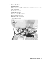
4. Disconnect the following: A Grounding screw B Bluetooth connector (if Bluetooth board is present, this will be connected) C AirPort connector D AC line filter connector E TMDS video connector F Inverter, speaker, fan connector G Optical cable and connector H Hard drive cable and connector I Power Supply connector iMac (USB 2.0) Take Apart - 13
4. Disconnect the following: A Grounding screw B Bluetooth connector (if Bluetooth board is present, this will be connected) C AirPort connector D AC line filter connector E TMDS video connector F Inverter, speaker, fan connector G Optical cable and connector H Hard drive cable and connector I Power Supply connector iMac (USB 2.0) Take Apart - 13

Service Source
Page 68
Fan iMac (USB 2.0) Take Apart - 59 Fan Tools This procedure requires the following tools: • Torx-15 screwdriver Part Location Preliminary Steps Before you begin, do the following: • Position the computer in the service stand. • Remove the user access plate. • Remove the bottom housing. • Remove the drive carrier assembly.
Fan iMac (USB 2.0) Take Apart - 59 Fan Tools This procedure requires the following tools: • Torx-15 screwdriver Part Location Preliminary Steps Before you begin, do the following: • Position the computer in the service stand. • Remove the user access plate. • Remove the bottom housing. • Remove the drive carrier assembly.

Service Source
Page 69
Procedure 1. The 20-inch iMac (USB 2.0) fan is different (identify by the amps highlighted below . 60 - Note: The replacement fan includes the mounting bracket. 3. Pull the fan out of the chassis (Faraday cage). Note: The fan on the 20-inch iMac (USB 2.0), 922-6215, is shown below ) from the fan used on the 15-inch and the 17-inch iMac (USB 2.0) computers. Remove the two fan screws and disconnect the fan connector. 2. iMac (USB 2.0) Take Apart Fan
Procedure 1. The 20-inch iMac (USB 2.0) fan is different (identify by the amps highlighted below . 60 - Note: The replacement fan includes the mounting bracket. 3. Pull the fan out of the chassis (Faraday cage). Note: The fan on the 20-inch iMac (USB 2.0), 922-6215, is shown below ) from the fan used on the 15-inch and the 17-inch iMac (USB 2.0) computers. Remove the two fan screws and disconnect the fan connector. 2. iMac (USB 2.0) Take Apart Fan

Service Source
Page 70
... mating surfaces, and reapply thermal paste to the topic "Thermal Paste Application" for service, you must tighten the four torx screws on the thermal pipe. 2. Fan iMac (USB 2.0) Take Apart - 61
... mating surfaces, and reapply thermal paste to the topic "Thermal Paste Application" for service, you must tighten the four torx screws on the thermal pipe. 2. Fan iMac (USB 2.0) Take Apart - 61

Service Source
Page 73
iMac (USB 2.0) Take Apart Fan Retainer Bracket (under fan) Tools This procedure requires the following tools: • Torx-10 screwdriver Part Location Preliminary Steps Before you begin, do the following: • Position the computer in the service stand. • Remove the user access plate. • Remove the bottom housing. • Remove the drive carrier assembly. • Remove the power supply. • Remove the fan. 64 - Fan Retainer Bracket (under fan)
iMac (USB 2.0) Take Apart Fan Retainer Bracket (under fan) Tools This procedure requires the following tools: • Torx-10 screwdriver Part Location Preliminary Steps Before you begin, do the following: • Position the computer in the service stand. • Remove the user access plate. • Remove the bottom housing. • Remove the drive carrier assembly. • Remove the power supply. • Remove the fan. 64 - Fan Retainer Bracket (under fan)

Service Source
Page 74
Procedure 1. Remove the four screws connecting the fan bracket to the chassis (Faraday cage). 2. For orientation purposes, the drive door would be on the right. Note the orientation of the chassis. Fan Retainer Bracket (under fan) iMac (USB 2.0) Take Apart - 65 Lift the fan bracket out of the neck cables (see below) in the fan bracket before removing the cables.
Procedure 1. Remove the four screws connecting the fan bracket to the chassis (Faraday cage). 2. For orientation purposes, the drive door would be on the right. Note the orientation of the chassis. Fan Retainer Bracket (under fan) iMac (USB 2.0) Take Apart - 65 Lift the fan bracket out of the neck cables (see below) in the fan bracket before removing the cables.

Service Source
Page 75
... components. Failure to follow these steps could cause the computer to ensure that the thermal pipe is opened for detailed information. 66 - iMac (USB 2.0) Take Apart Fan Retainer Bracket (under fan) If you do not have a torque driver, you must do two things: 1.You must tighten the four torx screws on the thermal...
... components. Failure to follow these steps could cause the computer to ensure that the thermal pipe is opened for detailed information. 66 - iMac (USB 2.0) Take Apart Fan Retainer Bracket (under fan) If you do not have a torque driver, you must do two things: 1.You must tighten the four torx screws on the thermal...

