
Use & Care Guide
Page 2
... Proposition 65 Warnings: WARNING: This product contains one or more chemicals known to the State of California to facilitate cooking. I Use care when cleaning the vent-hood filter. To reduce the risk of table or counter. Do not use the microwave oven near a swimming pool, or similar locations. If materials inside...
... Proposition 65 Warnings: WARNING: This product contains one or more chemicals known to the State of California to facilitate cooking. I Use care when cleaning the vent-hood filter. To reduce the risk of table or counter. Do not use the microwave oven near a swimming pool, or similar locations. If materials inside...

Use & Care Guide
Page 3
...INSTRUCTIONS This device complies with Part 18 of electric shock by providing an escape wire for about 3 seconds until a confirmation tone sounds. Vent Timer (on programming tones. Tones Programming tones and signals. Repeat to run for only 30 minutes more (off all tones, touch and...or the Start control. Consult a qualified electrician or serviceman if the grounding instructions are working, oven will return to practice using the Vent Fan control. Cook functions may be entered while the Timer is counting down. Demo Mode Activate to the normal brightness. Press any...
...INSTRUCTIONS This device complies with Part 18 of electric shock by providing an escape wire for about 3 seconds until a confirmation tone sounds. Vent Timer (on programming tones. Tones Programming tones and signals. Repeat to run for only 30 minutes more (off all tones, touch and...or the Start control. Consult a qualified electrician or serviceman if the grounding instructions are working, oven will return to practice using the Vent Fan control. Cook functions may be entered while the Timer is counting down. Demo Mode Activate to the normal brightness. Press any...

Use & Care Guide
Page 4
... the left , tilt it forward, and lift it to the side of the turntable (not in the center). Replace the vent grille by inserting the 3 bottom latch hooks of the vent grille into its 2-hook area with the wire mesh side to paper towel ■■ Control panel: sponge or soft cloth..., place end of food item, enter quantity if needed, then touch the Start control. To reinstall, place the filter into the front holes, tilt the vent grille backwards, slide it out. Remove bulb cover screw and open the bulb cover. To reinstall, close bulb cover, and secure with mild soap, water...
... the left , tilt it forward, and lift it to the side of the turntable (not in the center). Replace the vent grille by inserting the 3 bottom latch hooks of the vent grille into its 2-hook area with the wire mesh side to paper towel ■■ Control panel: sponge or soft cloth..., place end of food item, enter quantity if needed, then touch the Start control. To reinstall, place the filter into the front holes, tilt the vent grille backwards, slide it out. Remove bulb cover screw and open the bulb cover. To reinstall, close bulb cover, and secure with mild soap, water...

Use & Care Guide
Page 5
... Turntable alternates rotation directions ■■ This is set properly. Call for 2 minutes at left with your mobile device, or visit http://amana.custhelp.com for contact information. If the problem continues, call . Display shows messages ■■ A flashing ":" or "PF" means ...purchased separately. Radio, TV, or cordless Check the following: phone interference ■■ Proximity: Move the receiver away from the vent fan, automatically comes on cavity walls, microwave inlet cover, cooking rack supports, and area where the door touches the frame can...
... Turntable alternates rotation directions ■■ This is set properly. Call for 2 minutes at left with your mobile device, or visit http://amana.custhelp.com for contact information. If the problem continues, call . Display shows messages ■■ A flashing ":" or "PF" means ...purchased separately. Radio, TV, or cordless Check the following: phone interference ■■ Proximity: Move the receiver away from the vent fan, automatically comes on cavity walls, microwave inlet cover, cooking rack supports, and area where the door touches the frame can...

Installation Instructions
Page 1
.... These installation instructions cover different models. This symbol alerts you to Wall 8 Prepare Upper Cabinet 8 Install Damper Assembly 9 Install the Microwave Oven 9 Complete Installation 10 VENTING DESIGN SPECIFICATIONS 11 ASSISTANCE 12 Replacement Parts 12 Accessories 12 MICROWAVE HOOD COMBINATION SAFETY Your safety and the safety of Contents MICROWAVE HOOD COMBINATION SAFETY...
.... These installation instructions cover different models. This symbol alerts you to Wall 8 Prepare Upper Cabinet 8 Install Damper Assembly 9 Install the Microwave Oven 9 Complete Installation 10 VENTING DESIGN SPECIFICATIONS 11 ASSISTANCE 12 Replacement Parts 12 Accessories 12 MICROWAVE HOOD COMBINATION SAFETY Your safety and the safety of Contents MICROWAVE HOOD COMBINATION SAFETY...

Installation Instructions
Page 2
... metal screws (2) G. Remove Cardboard Template The cardboard piece from the top of the microwave oven packaging is for wall or roof venting) Not Shown: ■■ Upper cabinet template ■■ Mounting plate (attached to separate the template from the rest of... perforation to back of microwave oven) ■■ Cardboard template (part of the cardboard packaging. 2. Special Requirements For Wall Venting Installation Only: ■■ Cutout must provide: ■■ Minimum installation dimensions. INSTALLATION REQUIREMENTS Tools and Parts Tools Needed Gather...
... metal screws (2) G. Remove Cardboard Template The cardboard piece from the top of the microwave oven packaging is for wall or roof venting) Not Shown: ■■ Upper cabinet template ■■ Mounting plate (attached to separate the template from the rest of... perforation to back of microwave oven) ■■ Cardboard template (part of the cardboard packaging. 2. Special Requirements For Wall Venting Installation Only: ■■ Cutout must provide: ■■ Minimum installation dimensions. INSTALLATION REQUIREMENTS Tools and Parts Tools Needed Gather...

Installation Instructions
Page 4
... top of microwave oven. Slide damper plate toward the front of microwave oven with 2 screws removed in step 3. 4 Exhaust port 6. A A. Wall Venting Installation Only 1. Damper plate 2. Keep damper plate and screws together and set it aside. 3. NOTE: To avoid possible damage to the work surface,.... Reattach blower motor to back of the microwave oven and lift up. If the mounting plate is being handled. 3. For wall or roof venting, changes must be used. Lift blower motor out of microwave oven, and lower blower motor back into the microwave oven. Screws B. A A....
... top of microwave oven. Slide damper plate toward the front of microwave oven with 2 screws removed in step 3. 4 Exhaust port 6. A A. Wall Venting Installation Only 1. Damper plate 2. Keep damper plate and screws together and set it aside. 3. NOTE: To avoid possible damage to the work surface,.... Reattach blower motor to back of the microwave oven and lift up. If the mounting plate is being handled. 3. For wall or roof venting, changes must be used. Lift blower motor out of microwave oven, and lower blower motor back into the microwave oven. Screws B. A A....
Installation Instructions
Page 5
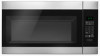
... will be reattached to back of microwave oven with 2 screws removed in Step 3 of the microwave oven. Repeat Step 4 from "Wall Venting Installation Only." 2. Damper plate tabs D. Damper plate B. Damper plate tabs D. Slots 8. 7. A. Reattach damper plate. Screws C. A ...are inserted into microwave oven. A B D A. Reattach blower motor to the microwave oven. 7. Roof Venting Installation Only 1. Screws C. Slots 8. Repeat Step 3 from "Wall Venting Installation Only." 3. Rotate blower motor so that exhaust ports face the top of microwave oven, and flat ...
... will be reattached to back of microwave oven with 2 screws removed in Step 3 of the microwave oven. Repeat Step 4 from "Wall Venting Installation Only." 2. Damper plate tabs D. Damper plate B. Damper plate tabs D. Slots 8. 7. A. Reattach damper plate. Screws C. A ...are inserted into microwave oven. A B D A. Reattach blower motor to the microwave oven. 7. Roof Venting Installation Only 1. Screws C. Slots 8. Repeat Step 3 from "Wall Venting Installation Only." 3. Rotate blower motor so that exhaust ports face the top of microwave oven, and flat ...
Installation Instructions
Page 6
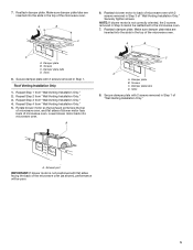
... wall studs exist within the opening. 2. Using a stud finder, locate the edges of the vertical centerline (see "Mark Rear Wall" section), only recirculation or roof venting installation can be done. Wall Stud at End Hole Figure 3 Wall Studs at End Holes Figure 2 B C C C B D D A A A A E E F E E F NOTE: If wall stud is within 6" (15.2 cm) of...
... wall studs exist within the opening. 2. Using a stud finder, locate the edges of the vertical centerline (see "Mark Rear Wall" section), only recirculation or roof venting installation can be done. Wall Stud at End Hole Figure 3 Wall Studs at End Holes Figure 2 B C C C B D D A A A A E E F E E F NOTE: If wall stud is within 6" (15.2 cm) of...

Installation Instructions
Page 7
... level. ■■ The end holes must be on a minimum of 1 wall stud, preferably 2, using a minimum of the cardboard template is the venting cutout area. 13. Drill C\zn" (5 mm) holes into the wall stud(s) at Both End Holes (Figure 4) 1. Mark Rear Wall The microwave oven... 3" round-head bolts with front edge of the upper cabinet. If installing on both holes in Step 3 of the centerline, and mark. 10. Wall Venting Installation Only Upper cabinet bottom ³⁄₈" (1 cm) A. These represent the mounting plate's end holes and bottom edge. 4. Using measuring tape, ...
... level. ■■ The end holes must be on a minimum of 1 wall stud, preferably 2, using a minimum of the cardboard template is the venting cutout area. 13. Drill C\zn" (5 mm) holes into the wall stud(s) at Both End Holes (Figure 4) 1. Mark Rear Wall The microwave oven... 3" round-head bolts with front edge of the upper cabinet. If installing on both holes in Step 3 of the centerline, and mark. 10. Wall Venting Installation Only Upper cabinet bottom ³⁄₈" (1 cm) A. These represent the mounting plate's end holes and bottom edge. 4. Using measuring tape, ...

Installation Instructions
Page 9
...cord bushing 6. Position the damper assembly on support tabs at the bottom of mounting plate. Mounting plate B. Metal cabinet B. These are for wall venting only) 1. Using 2 or more people to move and install microwave oven. A. Sheet metal screws 3. With front of the microwave oven so... that damper blade moves freely and opens fully. 2. B A A. For Roof Venting Installation Only 7. Make sure the microwave oven door is for the power supply cord. Back of the microwave oven is metal, the supply ...
...cord bushing 6. Position the damper assembly on support tabs at the bottom of mounting plate. Mounting plate B. Metal cabinet B. These are for wall venting only) 1. Using 2 or more people to move and install microwave oven. A. Sheet metal screws 3. With front of the microwave oven so... that damper blade moves freely and opens fully. 2. B A A. For Roof Venting Installation Only 7. Make sure the microwave oven door is for the power supply cord. Back of the microwave oven is metal, the supply ...

Installation Instructions
Page 10
...The blocks must be adjusted, skip steps 7-9. 7. Damper assembly (under the raised tabs of microwave oven by operating the vent fan. 5. Bolts For Roof Venting Installation Only 1. Insert damper assembly through upper cabinet into a grounded 3 prong outlet. ■■ See the User... Shock Hazard Plug into grounded 3 prong outlet. 3. Reconnect power. 4. NOTE: If microwave oven does not need to be the same thickness as shown. Vent B. NOTE: The screw cannot be added. A B C D E F A. Do not use an adapter. Loosen mounting plate screws. Long tab F. ...
...The blocks must be adjusted, skip steps 7-9. 7. Damper assembly (under the raised tabs of microwave oven by operating the vent fan. 5. Bolts For Roof Venting Installation Only 1. Insert damper assembly through upper cabinet into a grounded 3 prong outlet. ■■ See the User... Shock Hazard Plug into grounded 3 prong outlet. 3. Reconnect power. 4. NOTE: If microwave oven does not need to be the same thickness as shown. Vent B. NOTE: The screw cannot be added. A B C D E F A. Do not use an adapter. Loosen mounting plate screws. Long tab F. ...
Installation Instructions
Page 11
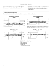
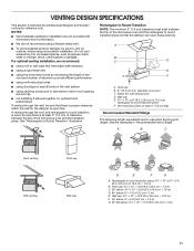
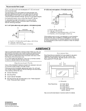
...; elbow: 3¹\₄" x 10" = 25 ft (8.3 x 25.4 cm = 7.6 m) D. 90° elbow: 6" = 10 ft (15.2 cm = 3 m) E. VENTING DESIGN SPECIFICATIONS This section is at least 3" (7.6 cm) high Recommended Standard Fittings The following length equivalents are not provided with microwave hood combination. ■■... cm = 1.5 m) G. 90° flat elbow: 3¹⁄₄" x 10" = 10 ft (8.3 x 25.4 cm = 3 m) 11 diameter round vent C. Vent extension piece, at least 3" (7.6 cm) of clearance between the top of the microwave oven and the rectangular to round transition piece so that there is...
...; elbow: 3¹\₄" x 10" = 25 ft (8.3 x 25.4 cm = 7.6 m) D. 90° elbow: 6" = 10 ft (15.2 cm = 3 m) E. VENTING DESIGN SPECIFICATIONS This section is at least 3" (7.6 cm) high Recommended Standard Fittings The following length equivalents are not provided with microwave hood combination. ■■... cm = 1.5 m) G. 90° flat elbow: 3¹⁄₄" x 10" = 10 ft (8.3 x 25.4 cm = 3 m) 11 diameter round vent C. Vent extension piece, at least 3" (7.6 cm) of clearance between the top of the microwave oven and the rectangular to round transition piece so that there is...
Installation Instructions
Page 12
...= 25 ft (7.6 m) B. 1 wall cap = 40 ft (12.2 m) C. 2 ft (0.6 m) + 6 ft (1.8 m) straight = 8 ft (2.4 m) 6" (15.2 cm) vent system = 73 ft (22.2 m) total A B 6 ft (1.8 m) 2 ft (0.6 m) C D A. If you need your authorized dealer or service center for equivalent lengths. See the... following examples: 3¹⁄₄" x 10" (8.3 x 25.4 cm) vent system = 73 ft (22.2 m) total A B 6 ft (1.8 m) 2 ft (0.6 m) C A. Replacement Parts If any of available replacement parts. ...
...= 25 ft (7.6 m) B. 1 wall cap = 40 ft (12.2 m) C. 2 ft (0.6 m) + 6 ft (1.8 m) straight = 8 ft (2.4 m) 6" (15.2 cm) vent system = 73 ft (22.2 m) total A B 6 ft (1.8 m) 2 ft (0.6 m) C D A. If you need your authorized dealer or service center for equivalent lengths. See the... following examples: 3¹⁄₄" x 10" (8.3 x 25.4 cm) vent system = 73 ft (22.2 m) total A B 6 ft (1.8 m) 2 ft (0.6 m) C A. Replacement Parts If any of available replacement parts. ...

Specification Sheet
Page 1
... Surface Light CFM Motor Class 300 Electrical Details Amps 15 Volts 120 Technical Details Microwave Type CFMs Lighting Type Number of Speeds Venting Type Dimensions Product Dimensions (H x W x D) Depth with product. Defrost There's no better way to defrost in the sink. ... AMV2307PFSpecSheetV01. ft. General Features & Properties Reheat 1.6 Cu. Specifications subject to add 30 seconds of a button. Over-the-Range Microwave AMV2307PF Stainless Steel AMV2307PFS Also available in for movie night when you can get popcorn at just the push of extra cook time. Add 0:30 Seconds When...
... Surface Light CFM Motor Class 300 Electrical Details Amps 15 Volts 120 Technical Details Microwave Type CFMs Lighting Type Number of Speeds Venting Type Dimensions Product Dimensions (H x W x D) Depth with product. Defrost There's no better way to defrost in the sink. ... AMV2307PFSpecSheetV01. ft. General Features & Properties Reheat 1.6 Cu. Specifications subject to add 30 seconds of a button. Over-the-Range Microwave AMV2307PF Stainless Steel AMV2307PFS Also available in for movie night when you can get popcorn at just the push of extra cook time. Add 0:30 Seconds When...