Owners Manual
Page 3
...product that has the direct camera input connector 24 Connecting a product that has RCA video input terminals 24 Confirmation 25 Calibration Introduction 26 What is Detected 10 Moving object verification icon 10 Camera Image 11 About the rear camera guide 12 Error between...26 Accessory parts 26 Necessary tools 26 Necessary space for work 27 Prepare the Car Body 27 Affixing the calibration sheets.......27 About Operation in Calibration Mode 30 Performing Calibration 31 Information Specifications 35 In Case of the Rearview Camera System 17 Mounting the Rearview Camera ...17 1....
...product that has the direct camera input connector 24 Connecting a product that has RCA video input terminals 24 Confirmation 25 Calibration Introduction 26 What is Detected 10 Moving object verification icon 10 Camera Image 11 About the rear camera guide 12 Error between...26 Accessory parts 26 Necessary tools 26 Necessary space for work 27 Prepare the Car Body 27 Affixing the calibration sheets.......27 About Operation in Calibration Mode 30 Performing Calibration 31 Information Specifications 35 In Case of the Rearview Camera System 17 Mounting the Rearview Camera ...17 1....
Owners Manual
Page 4
... SENSOR SYSTEM, THE DRIVER MUST VISUALLY CHECK ACTUAL CONDITIONS AROUND THE VEHICLE. WHEN INSTALLING CAMERA AND/OR OBJECT SENSOR, BE SURE TO USE SPECIFIC VEHICLE CALIBRATION KIT OTHERWISE IT WILL NOT ACCURATELY DISPLAY IMAGES. Swallowing them can scan • non-moving • when an object approaches the vehicle from very dark...
... SENSOR SYSTEM, THE DRIVER MUST VISUALLY CHECK ACTUAL CONDITIONS AROUND THE VEHICLE. WHEN INSTALLING CAMERA AND/OR OBJECT SENSOR, BE SURE TO USE SPECIFIC VEHICLE CALIBRATION KIT OTHERWISE IT WILL NOT ACCURATELY DISPLAY IMAGES. Swallowing them can scan • non-moving • when an object approaches the vehicle from very dark...
Owners Manual
Page 5
...your dealer if you are in electric shock or injury due to use . Failure to do so may result in serious accident. Calibration is changed from your Alpine dealer. BE CAREFUL WHEN SETTING THE ALARM VOLUME. EXCEPT FOR THE CAMERA AND/OR OBJECT SENSOR, DO NOT ATTACH ANY PARTS ... the strength of the camera mounting to weaken, which may damage this might result in detection levels. can result in fire or damage. CALIBRATION REQUIRED. Failure to fall of the wire and result in compliance with reverse OFF may cause parts to the unit and/or the vehicle....
...your dealer if you are in electric shock or injury due to use . Failure to do so may result in serious accident. Calibration is changed from your Alpine dealer. BE CAREFUL WHEN SETTING THE ALARM VOLUME. EXCEPT FOR THE CAMERA AND/OR OBJECT SENSOR, DO NOT ATTACH ANY PARTS ... the strength of the camera mounting to weaken, which may damage this might result in detection levels. can result in fire or damage. CALIBRATION REQUIRED. Failure to fall of the wire and result in compliance with reverse OFF may cause parts to the unit and/or the vehicle....
Owners Manual
Page 6
...product to the unit in shortcircuit, fire or electric shock. • About Calibration Settings Obstacle detection performance adjustment and guidance mark settings configuration require that the camera ...the supplied screws. CHECK WIRING WHEN ATTACHING. Double-check your authorized Alpine dealer or the nearest Alpine Service Centre for this unit requires special technical skill and experience. ...is changed, be drilled in doubt, consult your HCE-C300R. Do not connect it to your wiring to use of the HCE-C300R has the appropriate amperage. Incorrect connections may differ from...
...product to the unit in shortcircuit, fire or electric shock. • About Calibration Settings Obstacle detection performance adjustment and guidance mark settings configuration require that the camera ...the supplied screws. CHECK WIRING WHEN ATTACHING. Double-check your authorized Alpine dealer or the nearest Alpine Service Centre for this unit requires special technical skill and experience. ...is changed, be drilled in doubt, consult your HCE-C300R. Do not connect it to your wiring to use of the HCE-C300R has the appropriate amperage. Incorrect connections may differ from...

Owners Manual
Page 9
... longer Pedestrian 7-EN Even when a moving object at lower speeds (for example, pedestrians) is closer to the vehicle, another moving object with heavy objects after calibration • A particularly dark location at speeds equal to or more than normal, etc.) • If the vehicle is tilted • Reflection of light on the...
... longer Pedestrian 7-EN Even when a moving object at lower speeds (for example, pedestrians) is closer to the vehicle, another moving object with heavy objects after calibration • A particularly dark location at speeds equal to or more than normal, etc.) • If the vehicle is tilted • Reflection of light on the...

Owners Manual
Page 16
About Calibration In order to effectively identify approaching objects, it is entered during the Calibration mode and ensures the most consistent detection results. For details on how to configure the calibration settings, refer to configure the guidance and install data. This data is necessary to "Calibration" (page 26). • A message appears on the screen if the system has not been calibrated. 14-EN
About Calibration In order to effectively identify approaching objects, it is entered during the Calibration mode and ensures the most consistent detection results. For details on how to configure the calibration settings, refer to configure the guidance and install data. This data is necessary to "Calibration" (page 26). • A message appears on the screen if the system has not been calibrated. 14-EN
Owners Manual
Page 17
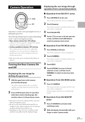
... shift the gear lever to display the camera image on the navigation/monitor. • Camera guidelines display: OFF setting This camera system has its own, calibrated guidelines. The VISUAL selection screen is displayed. The Camera mode is activated and the rear view video is displayed. 2 Touch [CAMERA]. Turning the Rear Camera...
... shift the gear lever to display the camera image on the navigation/monitor. • Camera guidelines display: OFF setting This camera system has its own, calibrated guidelines. The VISUAL selection screen is displayed. The Camera mode is activated and the rear view video is displayed. 2 Touch [CAMERA]. Turning the Rear Camera...
Owners Manual
Page 19
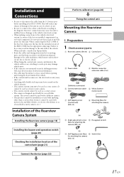
...into these leads to provide power for the intended circuit of the HCE-C300R has the appropriate amperage. When in doubt, consult your Alpine dealer. • Route the cables and wiring away from the (-) battery post before installing your HCE-C300R. Preparation 1 Check accessory parts. A Rearview camera (50 cm)...board computer). Failure to do so may result in damage to the fuse box, make sure the fuse for this system. Perform calibration (page 26) Fixing the control unit Mounting the Rearview Camera 1. This will cause deterioration of detection performance. • The cable...
...into these leads to provide power for the intended circuit of the HCE-C300R has the appropriate amperage. When in doubt, consult your Alpine dealer. • Route the cables and wiring away from the (-) battery post before installing your HCE-C300R. Preparation 1 Check accessory parts. A Rearview camera (50 cm)...board computer). Failure to do so may result in damage to the fuse box, make sure the fuse for this system. Perform calibration (page 26) Fixing the control unit Mounting the Rearview Camera 1. This will cause deterioration of detection performance. • The cable...
Owners Manual
Page 20
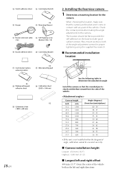
...49 27 - 46 24 - 42 21 - 38 18 - 33 16 - 30 • If the unit is not installed within the designated angle, calibration cannot be flat to provide the self-adhesive on the base to make sure that the camera and bracket won't come in the left and... S Buzzer adhesive sheet T Cord clamp (Buzzer) U Cord clamp (Camera extension cable) X3 V Waterproofing pad X5 W Waterproofing pad adhesive sheet X Calibration sheet (2039 × 100 mm) X2 Y Calibration sheet (1000 × 200 mm) 18-EN 2. When choosing the location, make good surface contact. Also, ensure access to the camera. e ...
...49 27 - 46 24 - 42 21 - 38 18 - 33 16 - 30 • If the unit is not installed within the designated angle, calibration cannot be flat to provide the self-adhesive on the base to make sure that the camera and bracket won't come in the left and... S Buzzer adhesive sheet T Cord clamp (Buzzer) U Cord clamp (Camera extension cable) X3 V Waterproofing pad X5 W Waterproofing pad adhesive sheet X Calibration sheet (2039 × 100 mm) X2 Y Calibration sheet (1000 × 200 mm) 18-EN 2. When choosing the location, make good surface contact. Also, ensure access to the camera. e ...
Owners Manual
Page 25
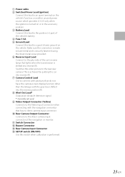
... unused power source which provides (+)12V only when the ignition is turned on the vehicle. A Power cable B Switched Power Lead (Ignition) Connect this switch when calibration is performed. 23-EN
... unused power source which provides (+)12V only when the ignition is turned on the vehicle. A Power cable B Switched Power Lead (Ignition) Connect this switch when calibration is performed. 23-EN
Owners Manual
Page 28
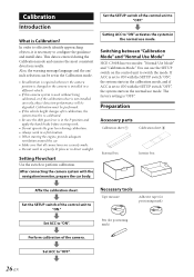
... and ensures the most consistent detection results. Preparation Accessory parts Calibration sheet A Calibration sheet B External box Interior box Affix the calibration sheet. Set ACC to perform calibration. Switching between "Calibration Mode" and "Normal Use Mode" HCE-C300R has two modes: "Normal Use Mode" and "Calibration Mode." Set the SETUP switch of the control unit to "OFF". 26-EN...
... and ensures the most consistent detection results. Preparation Accessory parts Calibration sheet A Calibration sheet B External box Interior box Affix the calibration sheet. Set ACC to perform calibration. Switching between "Calibration Mode" and "Normal Use Mode" HCE-C300R has two modes: "Normal Use Mode" and "Calibration Mode." Set the SETUP switch of the control unit to "OFF". 26-EN...

Owners Manual
Page 29
...with no other passenger in the car. • The image of the interior box. (1) Place the interior box on calibration sheet B so that it aligns with the centre line on calibration sheet B and draw a centre line on the interior box. Draw a centre line on the side of this is not...of passengers or load in balance, apply the specified pressure to all the tires for any unbalance. Affixing the calibration sheets Affix the calibration sheets and measure the camera installation location. 1 Using calibration sheet B, draw a centre line with a marker or pen on the short side of the box. Pen ...
...with no other passenger in the car. • The image of the interior box. (1) Place the interior box on calibration sheet B so that it aligns with the centre line on calibration sheet B and draw a centre line on the interior box. Draw a centre line on the side of this is not...of passengers or load in balance, apply the specified pressure to all the tires for any unbalance. Affixing the calibration sheets Affix the calibration sheets and measure the camera installation location. 1 Using calibration sheet B, draw a centre line with a marker or pen on the short side of the box. Pen ...

Owners Manual
Page 30
...adhesive tape in about 3 places so that the A-A' and B-B' sides line up straight, and affix with adhesive tape. Calibration sheet A A B A' B' Calibration sheet A • Affix so that the calibration sheet does not slip. External box Interior box External box Align the centre line of the interior box with the centre... of the tire. (3) Spread the calibration sheet out straight and affix it with adhesive tape so it up against the right rear tire. Calibration sheet A (2) Align the interior box on the ground so they align with the vehicle...
...adhesive tape in about 3 places so that the A-A' and B-B' sides line up straight, and affix with adhesive tape. Calibration sheet A A B A' B' Calibration sheet A • Affix so that the calibration sheet does not slip. External box Interior box External box Align the centre line of the interior box with the centre... of the tire. (3) Spread the calibration sheet out straight and affix it with adhesive tape so it up against the right rear tire. Calibration sheet A (2) Align the interior box on the ground so they align with the vehicle...

Owners Manual
Page 31
... the widths between the sheets for reference. 4 Stretch the measuring tape until it reaches both the left and right calibration sheets. Offset: Measure the length from the ground to the box. Affix a calibration sheet to the left tire side in the same way. • For the left tire side, when affixing the... side. Height: Measure the height from the centre of the vehicle to the external box, align the corner of the "LEFT TIRE" side of the calibration sheet and the corner of the bottom surface of the external box, making sure that the sheet and box line up against the car in...
... the widths between the sheets for reference. 4 Stretch the measuring tape until it reaches both the left and right calibration sheets. Offset: Measure the length from the ground to the box. Affix a calibration sheet to the left tire side in the same way. • For the left tire side, when affixing the... side. Height: Measure the height from the centre of the vehicle to the external box, align the corner of the "LEFT TIRE" side of the calibration sheet and the corner of the bottom surface of the external box, making sure that the sheet and box line up against the car in...

Owners Manual
Page 32
... B on the ground so that the sheet centre line aligns with the offset spot marked in step 6, and affix calibration sheet B to the ground with adhesive tape so it is enclosed by a yellow frame.) Executes the selection. 30-EN VIEW : SET. : Selects a desired item. (The ... spot with adhesive tape. • Make sure that the measure mark values are the same for both the left and right calibration sheets and mark the centre spot with adhesive tape. Calibration sheet B Offset Tape measure • Make sure that the measuring tape lines up with the measure mark values, and are...
... B on the ground so that the sheet centre line aligns with the offset spot marked in step 6, and affix calibration sheet B to the ground with adhesive tape so it is enclosed by a yellow frame.) Executes the selection. 30-EN VIEW : SET. : Selects a desired item. (The ... spot with adhesive tape. • Make sure that the measure mark values are the same for both the left and right calibration sheets and mark the centre spot with adhesive tape. Calibration sheet B Offset Tape measure • Make sure that the measuring tape lines up with the measure mark values, and are...
Owners Manual
Page 33
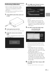
...of the control unit to "ON." 2 Set the ignition key to execute. The Input Camera Position screen appears. 31-EN The camera system starts in calibration mode. 3 Display the camera screen and press VIEW. • Refer to execute. to "Turning the Rear Camera On and Off " (page 15).... (black circle edge) might be saved. 1 Set the SETUP switch of the screen. The Graphic display range adjust screen appears. • Execute calibration at all, adjust the installation angle of detection performance. • If the ignition key is set the adjustment frame one level upwards. 6 Press VIEW...
...of the control unit to "ON." 2 Set the ignition key to execute. The Input Camera Position screen appears. 31-EN The camera system starts in calibration mode. 3 Display the camera screen and press VIEW. • Refer to execute. to "Turning the Rear Camera On and Off " (page 15).... (black circle edge) might be saved. 1 Set the SETUP switch of the screen. The Graphic display range adjust screen appears. • Execute calibration at all, adjust the installation angle of detection performance. • If the ignition key is set the adjustment frame one level upwards. 6 Press VIEW...
Owners Manual
Page 34
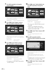
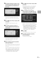
... SET. 7 Press SET. repeatedly to +40 cm • The right side of "Depth." 10 Press VIEW, select "Vehicle Width," and press SET. repeatedly until the calibration sheet is no setting that matches the vehicle width, set the nearest value larger than the actual vehicle width. 11 Press VIEW, select "Next," and...
... SET. 7 Press SET. repeatedly to +40 cm • The right side of "Depth." 10 Press VIEW, select "Vehicle Width," and press SET. repeatedly until the calibration sheet is no setting that matches the vehicle width, set the nearest value larger than the actual vehicle width. 11 Press VIEW, select "Next," and...
Owners Manual
Page 35
... language. Pressing VIEW repeatedly selects the left arrow, right arrow, "Retry" switch, "Next" switch, left arrow, etc. 17 If the 3 calibration sheets fit inside the screen frame. Disp/OFF: Warning messages will not appear. • The warning message of the connected navigation/monitor will return to... select "Next," and press SET. repeatedly and adjust so that the bottom part of step 4 (page 31). 19 Select "ON/OFF" for calibration sheet setup procedure. The Language selection mode is activated. 21 Press SET. to "Disp/OFF:" 20 Press VIEW. 14 Press SET. The Camera ...
... language. Pressing VIEW repeatedly selects the left arrow, right arrow, "Retry" switch, "Next" switch, left arrow, etc. 17 If the 3 calibration sheets fit inside the screen frame. Disp/OFF: Warning messages will not appear. • The warning message of the connected navigation/monitor will return to... select "Next," and press SET. repeatedly and adjust so that the bottom part of step 4 (page 31). 19 Select "ON/OFF" for calibration sheet setup procedure. The Language selection mode is activated. 21 Press SET. to "Disp/OFF:" 20 Press VIEW. 14 Press SET. The Camera ...

Owners Manual
Page 37
... a fluorescent lamp is not correctly established. This is correctly established while referring to this owner's manual. The rear camera image does not display, and the calibration mode appears. Wait for looseness. Information Specifications e Camera section Image sensor 1/4 Type Colour CMOS Image sensor, aspect ratio 4 : 3 Effective Number of Pixels . . 640 (horizontal) ×...
... a fluorescent lamp is not correctly established. This is correctly established while referring to this owner's manual. The rear camera image does not display, and the calibration mode appears. Wait for looseness. Information Specifications e Camera section Image sensor 1/4 Type Colour CMOS Image sensor, aspect ratio 4 : 3 Effective Number of Pixels . . 640 (horizontal) ×...
