

Operating Instructions
Page 2
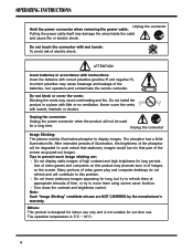
... Warning To assure continued FCC compliance, the user must the provided grounded power supply cord and the provided shielded video interface cables to connect to part 15 of the FCC Rules. 1. Connect the equipment into an outlet on , the user is properly grounded. Also, any unauthorized changes or modifications...
... Warning To assure continued FCC compliance, the user must the provided grounded power supply cord and the provided shielded video interface cables to connect to part 15 of the FCC Rules. 1. Connect the equipment into an outlet on , the user is properly grounded. Also, any unauthorized changes or modifications...
Operating Instructions
Page 5
... monitor illuminates phosphor to this product may cause breakage and leakage of high contrast and high brightness for long, but try to such extent that part of video game play and computer desktops do not refresh and will be used for out door use. Use of video games and computers on...
... monitor illuminates phosphor to this product may cause breakage and leakage of high contrast and high brightness for long, but try to such extent that part of video game play and computer desktops do not refresh and will be used for out door use. Use of video games and computers on...
Operating Instructions
Page 7
...fication 32 8. Product Features 8 3. Accessories 8 4. Cleaning and Simple Troubleshooting 34 6 Connection to External Equipment 15 6. Basic Operation 18 6.1 Power ON/OFF 18 6.2 Selection of Parts 9 4.1 Side View ...9 4.2 Front View ...10 4.3 Rear View ...11 4.4 Remote Control 12 5. Contents 1. Names and Functions of Input Mode 18 6.3 Other Function 19 6.4 OSD Option Adjustment...
...fication 32 8. Product Features 8 3. Accessories 8 4. Cleaning and Simple Troubleshooting 34 6 Connection to External Equipment 15 6. Basic Operation 18 6.1 Power ON/OFF 18 6.2 Selection of Parts 9 4.1 Side View ...9 4.2 Front View ...10 4.3 Rear View ...11 4.4 Remote Control 12 5. Contents 1. Names and Functions of Input Mode 18 6.3 Other Function 19 6.4 OSD Option Adjustment...

Operating Instructions
Page 10
Push the power switch (O: Off, I: On). Note: Shut down the power switch, turn on the front of Parts 4.1 Side View - 4. Names and Functions of the panel should now display red, indicating that the plasma is extinguished entirely. Power Switch Power Inlet 9 The power indicator on it again after the power indicator is in standby mode. Connect the power cable to the product then connect the main plug to the wall outlet. -
Push the power switch (O: Off, I: On). Note: Shut down the power switch, turn on the front of Parts 4.1 Side View - 4. Names and Functions of the panel should now display red, indicating that the plasma is extinguished entirely. Power Switch Power Inlet 9 The power indicator on it again after the power indicator is in standby mode. Connect the power cable to the product then connect the main plug to the wall outlet. -