
Service Manual
Page 1
SERVICE MANUAL Customer Model: PD P4206EM Safety Precaution Technical Specifications Block Diagram Circuit Diagram Basic Operations & Circuit Description Main IC Specifications Product Specification of PDP Module Trouble Shooting Manual of PDP Module Spare Part List Exploded View If you forget your V-Chip Password Software Upgrade This manual is the latest at the time of printing, and does not include the modification which may be made after the printing, by the constant improvement of product.
SERVICE MANUAL Customer Model: PD P4206EM Safety Precaution Technical Specifications Block Diagram Circuit Diagram Basic Operations & Circuit Description Main IC Specifications Product Specification of PDP Module Trouble Shooting Manual of PDP Module Spare Part List Exploded View If you forget your V-Chip Password Software Upgrade This manual is the latest at the time of printing, and does not include the modification which may be made after the printing, by the constant improvement of product.
Service Manual
Page 2
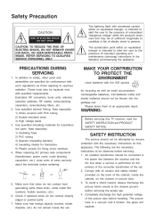
...Note especially: 1) Insulating Tape 2) PVC tubing 3) Spacers (insulating barriers) 4) Insulating sheets for transistors 5) Plastic screws for hazardous live parts. SAFETY INSTRUCTION The service should be of sufficient magnitude to constitute a risk of electric shock to persons. Safety Precaution CAUTION RISK OF ... alert the user to the presence of the picture tube before soldering. NO USER-SERVICEABLE PARTS INSIDE. PRECAUTIONS DURING SERVICING 1. In addition to safety, other parts and assemblies are the necessary instructions to be thrown into the garbage can. Use specified ...
...Note especially: 1) Insulating Tape 2) PVC tubing 3) Spacers (insulating barriers) 4) Insulating sheets for transistors 5) Plastic screws for hazardous live parts. SAFETY INSTRUCTION The service should be of sufficient magnitude to constitute a risk of electric shock to persons. Safety Precaution CAUTION RISK OF ... alert the user to the presence of the picture tube before soldering. NO USER-SERVICEABLE PARTS INSIDE. PRECAUTIONS DURING SERVICING 1. In addition to safety, other parts and assemblies are the necessary instructions to be thrown into the garbage can. Use specified ...

Service Manual
Page 3
... voltmeter having 5K ohms volt sensitivity or more than 6M ohms. AC VOLTMETER PRODUCT SAFETY NOTICE Many electrical and mechanical parts in the parts list may create shock, fire, or other hazards. 9. Before replacing any of these special safety characteristics are identified .... 7. Any value exceeding this apparatus have special safety-related characteristics. Measure the AC voltage across the combination of substitute replacement parts which have the same safety characteristics as the water pipe, conductor, etc. These characteristics are installed properly such as antennas, ...
... voltmeter having 5K ohms volt sensitivity or more than 6M ohms. AC VOLTMETER PRODUCT SAFETY NOTICE Many electrical and mechanical parts in the parts list may create shock, fire, or other hazards. 9. Before replacing any of these special safety characteristics are identified .... 7. Any value exceeding this apparatus have special safety-related characteristics. Measure the AC voltage across the combination of substitute replacement parts which have the same safety characteristics as the water pipe, conductor, etc. These characteristics are installed properly such as antennas, ...

Service Manual
Page 4
SIGNATURE : DATE : NOTE : Only documents stamped "Controlled Document" to be used for manufacture of production parts. Q/A DEPARTMENT ... ... MODEL : PDP4206EM 42" Plasma Monitor Technical DATE FIRST ISSUED Specifications ISSUE RAISED BY CHECKED BY NUMBER OF PAGES 1 REVISIONS ISSUED DATE DESCRIPTION 9 RAISED BY : SPECIFICATION AGREED : SIGNATURE DATE R & D DEPARTMENT ...COMMERCIAL DEPARTMENT ...PRODUCTION DEPARTMENT ... CUSTOMER ... ... ... ... SPECIFICATION APPROVED : .
SIGNATURE : DATE : NOTE : Only documents stamped "Controlled Document" to be used for manufacture of production parts. Q/A DEPARTMENT ... ... MODEL : PDP4206EM 42" Plasma Monitor Technical DATE FIRST ISSUED Specifications ISSUE RAISED BY CHECKED BY NUMBER OF PAGES 1 REVISIONS ISSUED DATE DESCRIPTION 9 RAISED BY : SPECIFICATION AGREED : SIGNATURE DATE R & D DEPARTMENT ...COMMERCIAL DEPARTMENT ...PRODUCTION DEPARTMENT ... CUSTOMER ... ... ... ... SPECIFICATION APPROVED : .
Service Manual
Page 37
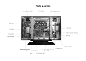
Parts position Internal Speaker (Right) Power Supply Internal Speaker (Left) Y-Drive Top Z-Sustainer Y-Sustainer External Speaker Terminals Y-Drive Bottom X left Extension Power SW EMI filter + AC Inlet only for the Model with Turner Main (Video) Stand Tuner/Audio X right Extension Remote control Receiver Local key Control (Signal Input)
Parts position Internal Speaker (Right) Power Supply Internal Speaker (Left) Y-Drive Top Z-Sustainer Y-Sustainer External Speaker Terminals Y-Drive Bottom X left Extension Power SW EMI filter + AC Inlet only for the Model with Turner Main (Video) Stand Tuner/Audio X right Extension Remote control Receiver Local key Control (Signal Input)
Service Manual
Page 45
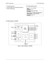
... SDRAM/SGRAM Interface Figure 1. nD S P C o r po r a t io n NV 3 2 0 D a ta S he et • Internet televisions • Home theater and multimedia televisions • Video conferencing 2.0 Ordering Information Part Number Package Description Version NV320 PQFP 208 Plastic quad flat package, 208 leads 1.0 3.0 Block Diagram of NV320
... SDRAM/SGRAM Interface Figure 1. nD S P C o r po r a t io n NV 3 2 0 D a ta S he et • Internet televisions • Home theater and multimedia televisions • Video conferencing 2.0 Ordering Information Part Number Package Description Version NV320 PQFP 208 Plastic quad flat package, 208 leads 1.0 3.0 Block Diagram of NV320
Service Manual
Page 66
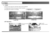
Basic 1. X RIGHT B/D Pull COF as shown in narrow. X B/D : receiving LOGIC signal from CONTROL B/D and make ADDRESS PULSE(generates Address discharge)by ON/OFF operation, and supplies this waveform to COF(data) Signal part Power part X LEFT B/D Lift up lock as shown in narrow. 3.
Basic 1. X RIGHT B/D Pull COF as shown in narrow. X B/D : receiving LOGIC signal from CONTROL B/D and make ADDRESS PULSE(generates Address discharge)by ON/OFF operation, and supplies this waveform to COF(data) Signal part Power part X LEFT B/D Lift up lock as shown in narrow. 3.
Service Manual
Page 67
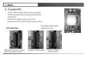
Basic 2. Condition in arrow. this waveform is pulled Pull FPC Connector as shown in Lock part is supplied to panel through FPC(Z). *composed with IPM,FET,DIODE, electrolytic capacitor ,E/R coil. * IPM (Intelligent Power Module) E/R(Energy recovery) Separate the fixed Screw of Z-Board. 3. Z sustain B/D : make SUSTAIN PULSE and ERASE PULSE that generates SUSTAIN discharge in arrow. 12 Pull out Lock as shown in panel by receiving LOGIC signal from CONTROL B/D.
Basic 2. Condition in arrow. this waveform is pulled Pull FPC Connector as shown in Lock part is supplied to panel through FPC(Z). *composed with IPM,FET,DIODE, electrolytic capacitor ,E/R coil. * IPM (Intelligent Power Module) E/R(Energy recovery) Separate the fixed Screw of Z-Board. 3. Z sustain B/D : make SUSTAIN PULSE and ERASE PULSE that generates SUSTAIN discharge in arrow. 12 Pull out Lock as shown in panel by receiving LOGIC signal from CONTROL B/D.
Service Manual
Page 70
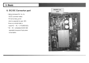
There is essential for each B/D. DC/DC con. part 15 DC/DC Converter part : Being impressed 5V, Va ,Vs, DC/DC converter makes 5V,Va,Vs,Vset_up,Vsc which is no DC/DC B/D in model 40 ¨• /42 ¨• (1 POWER B/D). * 50 ¨• 60 ¨• embedded DC/DC B/D separately because of high power consumption. Basic 6. 3.
There is essential for each B/D. DC/DC con. part 15 DC/DC Converter part : Being impressed 5V, Va ,Vs, DC/DC converter makes 5V,Va,Vs,Vset_up,Vsc which is no DC/DC B/D in model 40 ¨• /42 ¨• (1 POWER B/D). * 50 ¨• 60 ¨• embedded DC/DC B/D separately because of high power consumption. Basic 6. 3.
Service Manual
Page 78
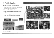
... between Y-SUS, Z-SUS B/D . Check Output voltage which is converted from AC V to DC V. 4. voltage Check (5V, Va, Vs) When PSU Protection occurred. Check each unit part of IC, resistor) 2. PSU(Power Supply Unit) 1. Trouble shooting. 3.
... between Y-SUS, Z-SUS B/D . Check Output voltage which is converted from AC V to DC V. 4. voltage Check (5V, Va, Vs) When PSU Protection occurred. Check each unit part of IC, resistor) 2. PSU(Power Supply Unit) 1. Trouble shooting. 3.

Service Manual
Page 85
Connector Check COF connector. COF 6 is torn partly Tearing 30 And then check input of COF resistor and IC. Trouble shooting. Check here Off 2. Vertical defect (bar) 1. Check here Bar If not connected well,it will Make a bar defect . Checking COF Confirm whether COF was torn. 4.
Connector Check COF connector. COF 6 is torn partly Tearing 30 And then check input of COF resistor and IC. Trouble shooting. Check here Off 2. Vertical defect (bar) 1. Check here Bar If not connected well,it will Make a bar defect . Checking COF Confirm whether COF was torn. 4.
Service Manual
Page 88
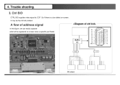
4. A flow of address signal In this figure, we can easily suppose what will be the ctrl b/d problem. Trouble shooting. 3. Ctrl B/D CTRL B/D supplies video signal to COF. Buffer IC 96 output So if there is a bar defect on screen, It may be appeared on screen when a specific part failed.
4. A flow of address signal In this figure, we can easily suppose what will be the ctrl b/d problem. Trouble shooting. 3. Ctrl B/D CTRL B/D supplies video signal to COF. Buffer IC 96 output So if there is a bar defect on screen, It may be appeared on screen when a specific part failed.

Service Manual
Page 89
MCM (Multi Chip Module) 4. Trouble shooting. MCM can not be replaced separately. So replace the ctrl b/d. Vertical defect (line) 1 line open or short with same distance. In this case, replace the panel. 1 electrode open 1 line open Line open or short This phenomenon is MCM of the Film and rear panel electrode problem. This is due to COF IC inside short or adherence part of Ctrl b/d defect.
MCM (Multi Chip Module) 4. Trouble shooting. MCM can not be replaced separately. So replace the ctrl b/d. Vertical defect (line) 1 line open or short with same distance. In this case, replace the panel. 1 electrode open 1 line open Line open or short This phenomenon is MCM of the Film and rear panel electrode problem. This is due to COF IC inside short or adherence part of Ctrl b/d defect.
Service Manual
Page 90
line defect from each parts • Case 1: Buffer IC fail COF IC 1,2 COF IC 3,4 192 line(96+96) open. 64 line open (with fixed interval there is on,off ...Repetition) 16 line open • case 2 : Array resistor fail COF IC1 16 line , COF IC2 16 line open • case3 : COF IC fail 96 line open. 96 line open Trouble shooting. 4.
line defect from each parts • Case 1: Buffer IC fail COF IC 1,2 COF IC 3,4 192 line(96+96) open. 64 line open (with fixed interval there is on,off ...Repetition) 16 line open • case 2 : Array resistor fail COF IC1 16 line , COF IC2 16 line open • case3 : COF IC fail 96 line open. 96 line open Trouble shooting. 4.

Service Manual
Page 91
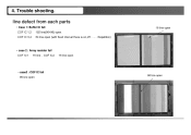
So check connectors (FPC, Y drv -Y drv) first. Trouble shooting. Connector It can be supplied to panel. In case of adherence part of the Film and rear panel electrode defect or panel electrode open,short , replace the panel. 1. Disconnected Horizontal bar Disconnected Screen off 4. Horizontal (bar) Most horizontal defects can make a horizontal bar that connector on Y b/d and Z b/d did not plugged well. Because sustain voltage can not be repaired.
So check connectors (FPC, Y drv -Y drv) first. Trouble shooting. Connector It can be supplied to panel. In case of adherence part of the Film and rear panel electrode defect or panel electrode open,short , replace the panel. 1. Disconnected Horizontal bar Disconnected Screen off 4. Horizontal (bar) Most horizontal defects can make a horizontal bar that connector on Y b/d and Z b/d did not plugged well. Because sustain voltage can not be repaired.
Service Manual
Page 92
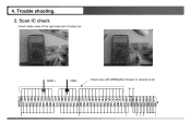
Check here with DMM(either forward or reverse is ok) 37 DMM + DMM - Trouble shooting. 2. Scan IC check Check diode value of the right side part of output pin. 4.
Check here with DMM(either forward or reverse is ok) 37 DMM + DMM - Trouble shooting. 2. Scan IC check Check diode value of the right side part of output pin. 4.
Service Manual
Page 95
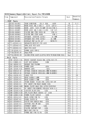
...-42D101-01 13 774P42D101-01 14 771E42D101-01 15 771L42D101-05 二. Mech Parts 1 200-42D121-21A 2 244-34B801-01 3 248-46D201-01 4 263-... 423-42D108-01 21 423-42D10C-01 22 423-42D10F-01 23 423-42D113-01 24 423-42D114-01 25 423-42D115-01 Report For PDP4206EM Unit Quantity Summary 0.3 1 1 1 3 1 1 1 1 1 1 1 1 1 1 1 2 2 1 1 2 2 28 4 2 1 1 1 1 1 ...BLACK ENG 42TD1 W/O TV GIFT BOX HANDLE 34B8 HANDLE FOR PLASMA POWER LENS 42D1 REMOTE LENS 42D1 SPONGE CUSHION 500X10X4.0MM W/ADHESI... PLATE AKAI ENG 42TD1(JIAYING) PC SHEET FOR REMOTE PCB42D1 94V0 0.3 CAUTION PLATE ENG 42D1 H SPK PLATE MAIN SANSUI 42" 42SB...
...-42D101-01 13 774P42D101-01 14 771E42D101-01 15 771L42D101-05 二. Mech Parts 1 200-42D121-21A 2 244-34B801-01 3 248-46D201-01 4 263-... 423-42D108-01 21 423-42D10C-01 22 423-42D10F-01 23 423-42D113-01 24 423-42D114-01 25 423-42D115-01 Report For PDP4206EM Unit Quantity Summary 0.3 1 1 1 3 1 1 1 1 1 1 1 1 1 1 1 2 2 1 1 2 2 28 4 2 1 1 1 1 1 ...BLACK ENG 42TD1 W/O TV GIFT BOX HANDLE 34B8 HANDLE FOR PLASMA POWER LENS 42D1 REMOTE LENS 42D1 SPONGE CUSHION 500X10X4.0MM W/ADHESI... PLATE AKAI ENG 42TD1(JIAYING) PC SHEET FOR REMOTE PCB42D1 94V0 0.3 CAUTION PLATE ENG 42D1 H SPK PLATE MAIN SANSUI 42" 42SB...
Service Manual
Page 99
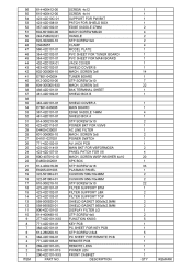
... PCB MAIN BKT FOR V6/FORMOSA PANEL PATCH FOR V6 MACH. 56 55 54 53 52 51 50 49 48 47 46 45 44 43 42 41 40 39 38 37 36 35 34 33 32 31 30 29 28 27 26 25 24 23 22 21 20 19 18 17...-42D101-01 614-260208-10 388-42D102-01 771-42D103-01 269-42D101-01L 263-42D101-01S 200-42D101-XXS PART NO. SCREW W/SP WASHER 4x10 SPK BOX STP SCREW 4x16 PLASMAS PANEL CUSHION 500x10x4MM CUSHION 950x10x4MM STP SCREW 3x10 FILTER SUPPORT BTM FILTER SUPPORT L&R FILTER SUPPORT TOP SHIELD GASKET 500x9x2.5MM...
... PCB MAIN BKT FOR V6/FORMOSA PANEL PATCH FOR V6 MACH. 56 55 54 53 52 51 50 49 48 47 46 45 44 43 42 41 40 39 38 37 36 35 34 33 32 31 30 29 28 27 26 25 24 23 22 21 20 19 18 17...-42D101-01 614-260208-10 388-42D102-01 771-42D103-01 269-42D101-01L 263-42D101-01S 200-42D101-XXS PART NO. SCREW W/SP WASHER 4x10 SPK BOX STP SCREW 4x16 PLASMAS PANEL CUSHION 500x10x4MM CUSHION 950x10x4MM STP SCREW 3x10 FILTER SUPPORT BTM FILTER SUPPORT L&R FILTER SUPPORT TOP SHIELD GASKET 500x9x2.5MM...