Aspire X1200 / X3200 Service Guide
Page 7
... External Modules Disassembly Flowchart 33 Removing the Side Panel 34 Removing the Font Bezel 35 Removing the Heat Sink Fan Assembly 36 Removing the Processor 38 Removing the Optical Drive 40 Removing the Hard Disk Drive 42 Removing the Power Supply 46 Removing the Memory Modules 49 Removing the ... Diagram and Board Layout 69 System Block Diagram 69 Board Layout 70 Mainboard 70 System Jumpers 71 FRU (Field Replaceable Unit) List 73 Aspire ASX1200/ ASX3200 Exploded Diagram 74 Aspire ASX1200/ ASX3200 FRU List (81.3V001.010G) 75 Technical Specifications 83 vii
... External Modules Disassembly Flowchart 33 Removing the Side Panel 34 Removing the Font Bezel 35 Removing the Heat Sink Fan Assembly 36 Removing the Processor 38 Removing the Optical Drive 40 Removing the Hard Disk Drive 42 Removing the Power Supply 46 Removing the Memory Modules 49 Removing the ... Diagram and Board Layout 69 System Block Diagram 69 Board Layout 70 Mainboard 70 System Jumpers 71 FRU (Field Replaceable Unit) List 73 Aspire ASX1200/ ASX3200 Exploded Diagram 74 Aspire ASX1200/ ASX3200 FRU List (81.3V001.010G) 75 Technical Specifications 83 vii
Aspire X1200 / X3200 Service Guide
Page 9
...-2300/2350/2400 or 4200+/4400+/4800+/5000+/5200+/5600+ processor T AMD Phenom X3 Triple-Core 8400/8450/8600/8650 processor T AMD Phenom X4 Quad-Core 9100e/9150e/9500/9550/9600/9650 processor T AMD Sempron LE-1250/1300 or 2100 processor Chipset T NVIDIA nForce MCP78 Memory subsystem T Supports up to... two DDR2-667 registered ECC modules Media storage T DVD-ROM SATA drive T Super-Multi SATA DVD drive T 160 GB SATA hard disk drive Serial ATA ...
...-2300/2350/2400 or 4200+/4400+/4800+/5000+/5200+/5600+ processor T AMD Phenom X3 Triple-Core 8400/8450/8600/8650 processor T AMD Phenom X4 Quad-Core 9100e/9150e/9500/9550/9600/9650 processor T AMD Sempron LE-1250/1300 or 2100 processor Chipset T NVIDIA nForce MCP78 Memory subsystem T Supports up to... two DDR2-667 registered ECC modules Media storage T DVD-ROM SATA drive T Super-Multi SATA DVD drive T 160 GB SATA hard disk drive Serial ATA ...
Aspire X1200 / X3200 Service Guide
Page 23
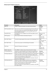
... SATA bus' baseline signal downwards by a small amount. When set the frame buffer size. When set to Manual. 256 MB Sets processor minimum and maximum frequency. 200 Minimum 100 Maximum 500 Controls the physical speed of system memory allocated solely for the onboard graphics controller. ...chipset modulates the PCI Express bus' baseline signal downwards by a small amount. Auto 200, 400, 600, 800 MHz, 1 GHz Controls the processor to configure memory timing and operation settings. When set to disabled, the chipset disables any modulation of the SATA bus' baseline signal. When set...
... SATA bus' baseline signal downwards by a small amount. When set the frame buffer size. When set to Manual. 256 MB Sets processor minimum and maximum frequency. 200 Minimum 100 Maximum 500 Controls the physical speed of system memory allocated solely for the onboard graphics controller. ...chipset modulates the PCI Express bus' baseline signal downwards by a small amount. Auto 200, 400, 600, 800 MHz, 1 GHz Controls the processor to configure memory timing and operation settings. When set to disabled, the chipset disables any modulation of the SATA bus' baseline signal. When set...
Aspire X1200 / X3200 Service Guide
Page 24
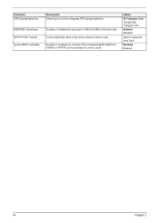
Enables or disables the processor's SSE and SSE2 instruction sets. Parameter iGPU Spread Spectrum SSE/SSE2 Instructions MCP78 PCIE Training System BIOS cacheable Description Allows you to FFFFFh by the processor's Level 2 cache. Option 50 Triangular Cntr 100/200/300 Triangular Cntr Enabled Disabled Gen2 if supported Only Gen1 Disabled Enabled 16 Chapter 2 Cards supporting Gen2 mode will be trained in Gen2 mode. Enables or disables the caching of the mainboard BIOS ROM from F0000h to set the integrated GPU spread spectrum.
Enables or disables the processor's SSE and SSE2 instruction sets. Parameter iGPU Spread Spectrum SSE/SSE2 Instructions MCP78 PCIE Training System BIOS cacheable Description Allows you to FFFFFh by the processor's Level 2 cache. Option 50 Triangular Cntr 100/200/300 Triangular Cntr Enabled Disabled Gen2 if supported Only Gen1 Disabled Enabled 16 Chapter 2 Cards supporting Gen2 mode will be trained in Gen2 mode. Enables or disables the caching of the mainboard BIOS ROM from F0000h to set the integrated GPU spread spectrum.
Aspire X1200 / X3200 Service Guide
Page 45
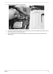
Do not let the thermal patch touch the work surface. 7. Disconnect the fan cable from both the heat sink and the processor socket retention plate. Chapter 3 37 Lay down the heat sink fan assembly in an upright position-with the thermal patch facing upward. Use an alcohol pad to wipe off the thermal grease from the mainboard. 6. 5.
Do not let the thermal patch touch the work surface. 7. Disconnect the fan cable from both the heat sink and the processor socket retention plate. Chapter 3 37 Lay down the heat sink fan assembly in an upright position-with the thermal patch facing upward. Use an alcohol pad to wipe off the thermal grease from the mainboard. 6. 5.
Aspire X1200 / X3200 Service Guide
Page 46
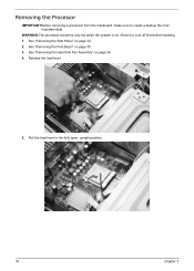
Pull the load lever to create a backup file of all important data. See "Removing the Font Bezel" on page 36. 4. See "Removing the Heat Sink Fan Assembly" on page 35. 3. Release the load lever. 5. WARNING:The processor becomes very hot when the system is on page 34. 2. See "Removing the Side Panel" on . Removing the Processor IMPORTANT:Before removing a processor from the mainboard, make sure to the fully open, upright position. 38 Chapter 3 Allow it to cool off first before handling. 1.
Pull the load lever to create a backup file of all important data. See "Removing the Font Bezel" on page 36. 4. See "Removing the Heat Sink Fan Assembly" on page 35. 3. Release the load lever. 5. WARNING:The processor becomes very hot when the system is on page 34. 2. See "Removing the Side Panel" on . Removing the Processor IMPORTANT:Before removing a processor from the mainboard, make sure to the fully open, upright position. 38 Chapter 3 Allow it to cool off first before handling. 1.
Aspire X1200 / X3200 Service Guide
Page 47
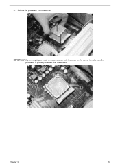
IMPORTANT:If you are going to install a new processor, note the arrow on the corner to make sure the processor is properly oriented over the socket. 6. Chapter 3 39 Pull out the processor from the socket.
IMPORTANT:If you are going to install a new processor, note the arrow on the corner to make sure the processor is properly oriented over the socket. 6. Chapter 3 39 Pull out the processor from the socket.
Aspire X1200 / X3200 Service Guide
Page 48
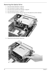
Release the drive bay retention release lever. 40 Chapter 3 See "Removing the Processor" on page 36. 4. See "Removing the Heat Sink Fan Assembly" on page 38. 5. Removing the Optical Drive 1. Disconnect the data and power cables from the rear of the optical drive and the mainboard. 6. See "Removing the Font Bezel" on page 34. 2. See "Removing the Side Panel" on page 35. 3.
Release the drive bay retention release lever. 40 Chapter 3 See "Removing the Processor" on page 36. 4. See "Removing the Heat Sink Fan Assembly" on page 38. 5. Removing the Optical Drive 1. Disconnect the data and power cables from the rear of the optical drive and the mainboard. 6. See "Removing the Font Bezel" on page 34. 2. See "Removing the Side Panel" on page 35. 3.
Aspire X1200 / X3200 Service Guide
Page 50
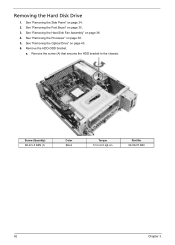
Removing the Hard Disk Drive 1. See "Removing the Heat Sink Fan Assembly" on page 35. 3. a. See "Removing the Font Bezel" on page 36. 4. Remove the screw (A) that secures the HDD bracket to 6.5 kgf-cm Part No. 86.00J07.B60 42 Chapter 3 See "Removing the Optical Drive" on page 38. 5. Remove the HDD-ODD bracket. Screw (Quantity) #6-32 L5 BZN (1) Color Black Torque 5.5 to the chassis. See "Removing the Processor" on page 40. 6. See "Removing the Side Panel" on page 34. 2.
Removing the Hard Disk Drive 1. See "Removing the Heat Sink Fan Assembly" on page 35. 3. a. See "Removing the Font Bezel" on page 36. 4. Remove the screw (A) that secures the HDD bracket to 6.5 kgf-cm Part No. 86.00J07.B60 42 Chapter 3 See "Removing the Optical Drive" on page 38. 5. Remove the HDD-ODD bracket. Screw (Quantity) #6-32 L5 BZN (1) Color Black Torque 5.5 to the chassis. See "Removing the Processor" on page 40. 6. See "Removing the Side Panel" on page 34. 2.
Aspire X1200 / X3200 Service Guide
Page 54
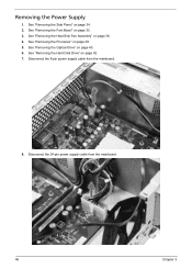
See "Removing the Heat Sink Fan Assembly" on page 40. 6. See "Removing the Optical Drive" on page 36. 4. Disconnect the 24-pin power supply cable from the mainboard. 8. See "Removing the Hard Disk Drive" on page 34. 2. See "Removing the Side Panel" on page 42. 7. Disconnect the 8-pin power supply cable from the mainboard. 46 Chapter 3 Removing the Power Supply 1. See "Removing the Processor" on page 35. 3. See "Removing the Font Bezel" on page 38. 5.
See "Removing the Heat Sink Fan Assembly" on page 40. 6. See "Removing the Optical Drive" on page 36. 4. Disconnect the 24-pin power supply cable from the mainboard. 8. See "Removing the Hard Disk Drive" on page 34. 2. See "Removing the Side Panel" on page 42. 7. Disconnect the 8-pin power supply cable from the mainboard. 46 Chapter 3 Removing the Power Supply 1. See "Removing the Processor" on page 35. 3. See "Removing the Font Bezel" on page 38. 5.
Aspire X1200 / X3200 Service Guide
Page 57
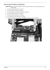
See "Removing the Font Bezel" on page 36. 4. See "Removing the Heat Sink Fan Assembly" on page 35. 3. See "Removing the Hard Disk Drive" on page 38. 5. Press the holding clips on both sides of the DIMM slot outward to create a backup file of all important data. 1. Chapter 3 49 See "Removing the Processor" on page 42. 7. See "Removing the Side Panel" on page 40. 6. Removing the Memory Modules IMPORTANT:Before removing any DIMM from the memory board, make sure to release the DIMM. See "Removing the Optical Drive" on page 34. 2.
See "Removing the Font Bezel" on page 36. 4. See "Removing the Heat Sink Fan Assembly" on page 35. 3. See "Removing the Hard Disk Drive" on page 38. 5. Press the holding clips on both sides of the DIMM slot outward to create a backup file of all important data. 1. Chapter 3 49 See "Removing the Processor" on page 42. 7. See "Removing the Side Panel" on page 40. 6. Removing the Memory Modules IMPORTANT:Before removing any DIMM from the memory board, make sure to release the DIMM. See "Removing the Optical Drive" on page 34. 2.
Aspire X1200 / X3200 Service Guide
Page 59
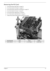
Remove the screw (A) that secures the card to 6.5 kgf-cm Part No. 86.00J07.B60 Chapter 3 51 Screw (Quantity) #6-32 L5 BZN (1) Color Black Torque 5.5 to the chassis. See "Removing the Processor" on page 36. 4. See "Removing the Heat Sink Fan Assembly" on page 38. 5. See "Removing the Side Panel" on page 42. 7. See "Removing the Hard Disk Drive" on page 34. 2. See "Removing the Font Bezel" on page 40. 6. See "Removing the Optical Drive" on page 35. 3. Removing the PCI Card 1.
Remove the screw (A) that secures the card to 6.5 kgf-cm Part No. 86.00J07.B60 Chapter 3 51 Screw (Quantity) #6-32 L5 BZN (1) Color Black Torque 5.5 to the chassis. See "Removing the Processor" on page 36. 4. See "Removing the Heat Sink Fan Assembly" on page 38. 5. See "Removing the Side Panel" on page 42. 7. See "Removing the Hard Disk Drive" on page 34. 2. See "Removing the Font Bezel" on page 40. 6. See "Removing the Optical Drive" on page 35. 3. Removing the PCI Card 1.
Aspire X1200 / X3200 Service Guide
Page 61
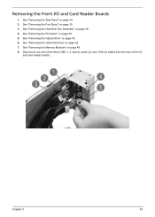
Removing the Front I /O and card reader boards. See "Removing the Optical Drive" on page 49. 8. See "Removing the Memory Modules" on page 40. 6. See "Removing the Heat Sink Fan Assembly" on page 38. 5. See "Removing the Processor" on page 36. 4. See "Removing the Font Bezel" on page 42. 7. Disconnect one end of the three USB (1, 2, and 4), audio (2), and 1394 (5) cables from the rear of the I /O and Card Reader Boards 1. See "Removing the Hard Disk Drive" on page 35. 3. See "Removing the Side Panel" on page 34. 2. Chapter 3 53
Removing the Front I /O and card reader boards. See "Removing the Optical Drive" on page 49. 8. See "Removing the Memory Modules" on page 40. 6. See "Removing the Heat Sink Fan Assembly" on page 38. 5. See "Removing the Processor" on page 36. 4. See "Removing the Font Bezel" on page 42. 7. Disconnect one end of the three USB (1, 2, and 4), audio (2), and 1394 (5) cables from the rear of the I /O and Card Reader Boards 1. See "Removing the Hard Disk Drive" on page 35. 3. See "Removing the Side Panel" on page 34. 2. Chapter 3 53
Aspire X1200 / X3200 Service Guide
Page 65
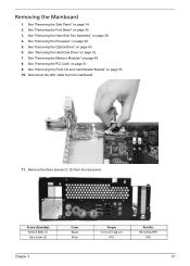
... from the rear panel. See "Removing the Heat Sink Fan Assembly" on page 34. 2. See "Removing the Font Bezel" on page 38. 5. See "Removing the Processor" on page 35. 3. See "Removing the PCI Card" on page 40. 6. See "Removing the Optical Drive" on page 51. 9. See "Removing the Front I/O and Card...
... from the rear panel. See "Removing the Heat Sink Fan Assembly" on page 34. 2. See "Removing the Font Bezel" on page 38. 5. See "Removing the Processor" on page 35. 3. See "Removing the PCI Card" on page 40. 6. See "Removing the Optical Drive" on page 51. 9. See "Removing the Front I/O and Card...
Aspire X1200 / X3200 Service Guide
Page 72
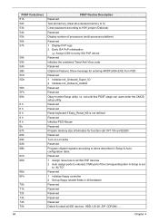
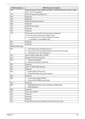
... 73h 74h 75h POST Routine Description Reserved Test all memory (clear all extended memory to 0) Clear password according to H/W jumper (Optional) Reserved Display number of processors (multi-processor platform) Reserved 1 Display PnP logo 2 Early ISA PnP initialization T Assign CSN to every ISA PnP device Reserved Initialize the combined Trend Anti-Virus code...
... 73h 74h 75h POST Routine Description Reserved Test all memory (clear all extended memory to 0) Clear password according to H/W jumper (Optional) Reserved Display number of processors (multi-processor platform) Reserved 1 Display PnP logo 2 Early ISA PnP initialization T Assign CSN to every ISA PnP device Reserved Initialize the combined Trend Anti-Virus code...
Aspire X1200 / X3200 Service Guide
Page 73
Detect serial ports & parallel ports Reserved Reserved Detect & install co-processor Reserved Init HDD write protect Reserved Reserved Switch back to CMOS setup 2 APM Initialization Reserved Clear noise of the memory Reserved 1 Invoke all ISA adapter ...
Detect serial ports & parallel ports Reserved Reserved Detect & install co-processor Reserved Init HDD write protect Reserved Reserved Switch back to CMOS setup 2 APM Initialization Reserved Clear noise of the memory Reserved 1 Invoke all ISA adapter ...
Aspire X1200 / X3200 Service Guide
Page 78
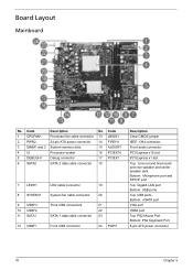
... cable connector 13 JBIOS1 2 PWR2 24-pin ATX power connector 14 FIREH1 3 DIMM1 and 2 System memory slots 15 AUDIOF1 4 UI Processor socket 16 PCIEX16 5 DEBUGH1 Debug connector 17 PCIEX1 6 SATA2 SATA 2 data cable connector 18 7 LEDH1 8 SYSFAN1 9 USBF3 10 USBF2 11 SATA1 12 USBF1 LED cable ...
... cable connector 13 JBIOS1 2 PWR2 24-pin ATX power connector 14 FIREH1 3 DIMM1 and 2 System memory slots 15 AUDIOF1 4 UI Processor socket 16 PCIEX16 5 DEBUGH1 Debug connector 17 PCIEX1 6 SATA2 SATA 2 data cable connector 18 7 LEDH1 8 SYSFAN1 9 USBF3 10 USBF2 11 SATA1 12 USBF1 LED cable ...
Aspire X1200 / X3200 Service Guide
Page 91
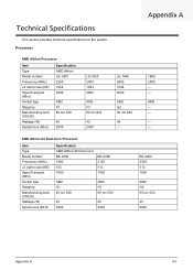
Technical Specifications This section provides technical specifications for the system. Processor AMD Athlon Processor Item Type Model number Frequency (MHz) L2 cache size (KB) HyperTransport (MHz) Socket type Stepping Manufacturing tech (CMOS) Wattage (W) System bus (MHz) Specification AMD ... 2000 AM2 F3 90 nm SOl 45 2000 LE-1640 2600 1024 2000 AM2 G2 90 nm SOI 45 - AM2 - - - - AMD Athlon X2 Dual-Core Processor Item Type Model number Frequency (MHz) L2 cache size (KB) HyperTransport (MHz) Socket type Stepping Manufacturing tech (CMOS) Wattage (W) System bus (MHz) Specification AMD ...
Technical Specifications This section provides technical specifications for the system. Processor AMD Athlon Processor Item Type Model number Frequency (MHz) L2 cache size (KB) HyperTransport (MHz) Socket type Stepping Manufacturing tech (CMOS) Wattage (W) System bus (MHz) Specification AMD ... 2000 AM2 F3 90 nm SOl 45 2000 LE-1640 2600 1024 2000 AM2 G2 90 nm SOI 45 - AM2 - - - - AMD Athlon X2 Dual-Core Processor Item Type Model number Frequency (MHz) L2 cache size (KB) HyperTransport (MHz) Socket type Stepping Manufacturing tech (CMOS) Wattage (W) System bus (MHz) Specification AMD ...
Aspire X1200 / X3200 Service Guide
Page 92
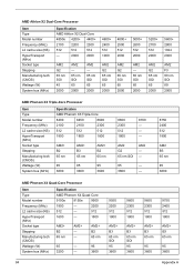
... 512 2000 AM2 G2 65 nm SOl 65 2000 5600+ 2800 1024 2000 AM2 F3 90 nm SOI 89 2000 AMD Phenom X3 Triple-Core Processor Item Type Model number Frequency (MHz) L2 cache size (KB) HyperTransport (MHz) Socket type Stepping Manufacturing tech (CMOS) Wattage (W) System bus (MHz) Specification ...84 Appendix A AM2 G2 65 nm SOl AM2 - - 95 - 3600 - 8750 2400 512 1800 AM2 B3 65 nm 95 3600 AMD Phenom X4 Quad-Core Processor Item Type Model number Frequency (MHz) L2 cache size (KB) HyperTransport (MHz) Socket type Stepping Manufacturing tech (CMOS) Wattage (W) System bus (MHz) Specification AMD...
... 512 2000 AM2 G2 65 nm SOl 65 2000 5600+ 2800 1024 2000 AM2 F3 90 nm SOI 89 2000 AMD Phenom X3 Triple-Core Processor Item Type Model number Frequency (MHz) L2 cache size (KB) HyperTransport (MHz) Socket type Stepping Manufacturing tech (CMOS) Wattage (W) System bus (MHz) Specification ...84 Appendix A AM2 G2 65 nm SOl AM2 - - 95 - 3600 - 8750 2400 512 1800 AM2 B3 65 nm 95 3600 AMD Phenom X4 Quad-Core Processor Item Type Model number Frequency (MHz) L2 cache size (KB) HyperTransport (MHz) Socket type Stepping Manufacturing tech (CMOS) Wattage (W) System bus (MHz) Specification AMD...


