
X203W LCD Monitor User's Guide
Page 1
...qualified technician should not be sure to unplug the monitor first. Connecting Your Monitor to the computer. c. (only Dual-Input Model) Connect one end of the 24-pin DVI cable to hold the plug, not the cable, when disconnecting the monitor from an electrical outlet. · Openings in ...the computer. Turn off . Connect power cord Connect the power cord to the monitor, then to diagnose the problem. Ensure that the computer is electrically rated to perform this monitor LCD Monitor Quick Setup Guide Operationg Detail Please refer to rest on the power cable, and...
...qualified technician should not be sure to unplug the monitor first. Connecting Your Monitor to the computer. c. (only Dual-Input Model) Connect one end of the 24-pin DVI cable to hold the plug, not the cable, when disconnecting the monitor from an electrical outlet. · Openings in ...the computer. Turn off . Connect power cord Connect the power cord to the monitor, then to diagnose the problem. Ensure that the computer is electrically rated to perform this monitor LCD Monitor Quick Setup Guide Operationg Detail Please refer to rest on the power cable, and...

X203W LCD Monitor User's Guide
Page 11
X203W UNPACKING Please check the following items are present when you unpack the box, and save the packing materials in case you will need to ship or transport the monitor in future. · LCD Monitor · D-Sub Cable · DVI Cable · AC Power Cord (Only Dual-Input Model) · User Manual · Quick Start Guide EN-5
X203W UNPACKING Please check the following items are present when you unpack the box, and save the packing materials in case you will need to ship or transport the monitor in future. · LCD Monitor · D-Sub Cable · DVI Cable · AC Power Cord (Only Dual-Input Model) · User Manual · Quick Start Guide EN-5

X203W LCD Monitor User's Guide
Page 18
...the power cord to the monitor, then to the computer. 1-2 Digital Cable (Only Dual-Input Model) a. This sequence is very important. 4. b. Connect the VGA video cable to a properly grounded AC outlet. 3. Connect one end of the 24-pin DVI cable to the back of the monitor and connect the other ...end to diagnose the problem. If the monitor still does not function properly, please refer to the troubleshooting section to the computer's port. 2. ...
...the power cord to the monitor, then to the computer. 1-2 Digital Cable (Only Dual-Input Model) a. This sequence is very important. 4. b. Connect the VGA video cable to a properly grounded AC outlet. 3. Connect one end of the 24-pin DVI cable to the back of the monitor and connect the other ...end to diagnose the problem. If the monitor still does not function properly, please refer to the troubleshooting section to the computer's port. 2. ...

X203W LCD Monitor User's Guide
Page 23
.... Position Description Adjust the horizontal position of current input timing. N/A Analog Select input signal from analog (D-Sub) N/A Digital (only DualInputModel) Select input signal from digital(DVI) (only Dual-Input Model) N/A DDC/CI Turn ON/OFF DDC/CI support N/A Information Show the resolution, H/V frequency andinput port of the OSD. Main Menu Icon...
.... Position Description Adjust the horizontal position of current input timing. N/A Analog Select input signal from analog (D-Sub) N/A Digital (only DualInputModel) Select input signal from digital(DVI) (only Dual-Input Model) N/A DDC/CI Turn ON/OFF DDC/CI support N/A Information Show the resolution, H/V frequency andinput port of the OSD. Main Menu Icon...
X203W LCD Monitor User's Guide
Page 26
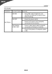
(DVI Mode) X203W Problems No Picture Current Status Remedy LED ON · Using OSD, adjust brightness and contrast to maximum or reset to the monitor. EN-20 LED OFF · Check the power switch. · Check if AC power cord is ON. LED displays amber color · Check if video signal cable is properly connected at the back of monitor. · Check if the power of computer system is properly connected to their default settings.
(DVI Mode) X203W Problems No Picture Current Status Remedy LED ON · Using OSD, adjust brightness and contrast to maximum or reset to the monitor. EN-20 LED OFF · Check the power switch. · Check if AC power cord is ON. LED displays amber color · Check if video signal cable is properly connected at the back of monitor. · Check if the power of computer system is properly connected to their default settings.

Acer X203H Service Guide
Page 5
... X203H is defined as our new 20'W model in ACER V series which will be "User preset" mode. * 1. X203H adopts SEC LTM200KT03 and LGD LM200WD1-TLC1. of monitor need to warm up at 50. * 2. ACM 2. There are double input types, D-sub, and DVI. in Qisda. X203H is shown as 20'W LCD Monitor supports 1600(H) x 900(V) resolution with Scaling...
... X203H is defined as our new 20'W model in ACER V series which will be "User preset" mode. * 1. X203H adopts SEC LTM200KT03 and LGD LM200WD1-TLC1. of monitor need to warm up at 50. * 2. ACM 2. There are double input types, D-sub, and DVI. in Qisda. X203H is shown as 20'W LCD Monitor supports 1600(H) x 900(V) resolution with Scaling...

Acer X203H Service Guide
Page 7
... 30 mm Color: Black Length: 1800 +/- 50 mm See Note-1 OK N.A Remark √ √ √ For 15-pin D-sub See Note-2 √ For 24-pin DVI-D See Note-3 √ Separate analog R/G/B √ 700 mV (peak to peak) √ 75 Ohms +/- 1.5 Ohms √ Separate H/V-sync Composite H/V-sync √ (Positive/... 2.2KΩ(pull down) √ 0.7µs < H-SPW 1H < V-SPW √ 600mV for each differential line √ 50 Ohm TDR Scan needed for DVI cable √ and interface board For 19-pin HDMI For 15-pin D-sub For 15-pin D-sub Refer to VESA VSIS Standard V1R1 10KΩ...
... 30 mm Color: Black Length: 1800 +/- 50 mm See Note-1 OK N.A Remark √ √ √ For 15-pin D-sub See Note-2 √ For 24-pin DVI-D See Note-3 √ Separate analog R/G/B √ 700 mV (peak to peak) √ 75 Ohms +/- 1.5 Ohms √ Separate H/V-sync Composite H/V-sync √ (Positive/... 2.2KΩ(pull down) √ 0.7µs < H-SPW 1H < V-SPW √ 600mV for each differential line √ 50 Ohm TDR Scan needed for DVI cable √ and interface board For 19-pin HDMI For 15-pin D-sub For 15-pin D-sub Refer to VESA VSIS Standard V1R1 10KΩ...
Acer X203H Service Guide
Page 8
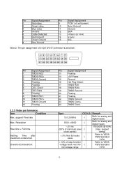
... Pin Signal Assignment 13 Floating 14 +5V Power 15 Ground 16 Hot Plug Detect 17 TMDS RX0- 18 TMDS RX0+ 19 TMDS Ground 20 Floating 21 Floating 22 TMDS Ground 23 TMDS Clock+ 24 TMDS Clock- support Pixel rate Max. Spec 151.25 MHz OK N.A √...; 1600 x 9000 √ < 5 ms (50% of minimum pixel √ clock period) < 5% final full-scale value √ < 12% of 24-pin DVI-D connector is as below, Pin Signal Assignment 1 TMDS RX2- 2 TMDS RX2+ 3 TMDS Ground 4 Floating 5 Floating 6 DDC Clock 7 DDC Data 8 Floating 9 TMDS RX1- 10...
... Pin Signal Assignment 13 Floating 14 +5V Power 15 Ground 16 Hot Plug Detect 17 TMDS RX0- 18 TMDS RX0+ 19 TMDS Ground 20 Floating 21 Floating 22 TMDS Ground 23 TMDS Clock+ 24 TMDS Clock- support Pixel rate Max. Spec 151.25 MHz OK N.A √...; 1600 x 9000 √ < 5 ms (50% of minimum pixel √ clock period) < 5% final full-scale value √ < 12% of 24-pin DVI-D connector is as below, Pin Signal Assignment 1 TMDS RX2- 2 TMDS RX2+ 3 TMDS Ground 4 Floating 5 Floating 6 DDC Clock 7 DDC Data 8 Floating 9 TMDS RX1- 10...

Acer X203H Service Guide
Page 16
... position OSD Vertical position √ From 10 sec to 120 sec √ EMEA/Non-EMEA languages for Asia/Europe √ Version Recall All √ D-sub DVI √ For input timing √ √ √ √ Full/Aspect √ ON/OFF √ ON/OFF √ N.A Remark √ √ √ √ Right/left key...
... position OSD Vertical position √ From 10 sec to 120 sec √ EMEA/Non-EMEA languages for Asia/Europe √ Version Recall All √ D-sub DVI √ For input timing √ √ √ √ Full/Aspect √ ON/OFF √ ON/OFF √ N.A Remark √ √ √ √ Right/left key...

Acer X203H Service Guide
Page 25
Fasten the LVDS to 10 panel and fix the Main- BKT to CLM-F Stick one to four. 2/4,based on the under between panel and Main-BTK only for fooling PC Card go with Screw-driver by one Al foil on the 11 right between pane land Main-BTK only for SEC panel 12 1 2 Stick two pieces of Al foil on DVI. - 25 - 9 Scan for SEC panel The position refer to the picture Lock screws of side on Attention the order 13 Main-Chassis with panel.
Fasten the LVDS to 10 panel and fix the Main- BKT to CLM-F Stick one to four. 2/4,based on the under between panel and Main-BTK only for fooling PC Card go with Screw-driver by one Al foil on the 11 right between pane land Main-BTK only for SEC panel 12 1 2 Stick two pieces of Al foil on DVI. - 25 - 9 Scan for SEC panel The position refer to the picture Lock screws of side on Attention the order 13 Main-Chassis with panel.
Acer X203H Service Guide
Page 36
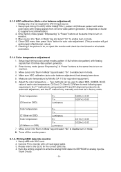
...optimal gain/offset(clamp) values) 5. Setup a PC with Analog signals from Chroma video pattern generator. (it is ok, or reject this monitor and check its circuit board or wire/cable connection. 5.1.4 Color temperature adjustment 1. Make sure ADC calibration (auto color balance adjustment) had ...Color temperature X+- 0.313+(-) 0.03 Y+- 0.329+(-) 0.03 (C3/Warm on OSD) Luminance 7. Close OSD menu then press "Auto" button for DVI-D input source 1. Move cursor into "Burn-in Mode" tag and select "No" to any preset modes, pattern 41(full white color pattern) with...
...optimal gain/offset(clamp) values) 5. Setup a PC with Analog signals from Chroma video pattern generator. (it is ok, or reject this monitor and check its circuit board or wire/cable connection. 5.1.4 Color temperature adjustment 1. Make sure ADC calibration (auto color balance adjustment) had ...Color temperature X+- 0.313+(-) 0.03 Y+- 0.329+(-) 0.03 (C3/Warm on OSD) Luminance 7. Close OSD menu then press "Auto" button for DVI-D input source 1. Move cursor into "Burn-in Mode" tag and select "No" to any preset modes, pattern 41(full white color pattern) with...

Acer X203H Service Guide
Page 37
Read both EEPROM data and confirm it to match with the Q212 definition. (Note : The DVI-D input may not operation correctly if the digital EDID data do not exist.) - 37 - 5. Repeat step 4 and write the digital EDID data into EEPROM for DVI-D input(ie. 24-pin DVID). 6.
Read both EEPROM data and confirm it to match with the Q212 definition. (Note : The DVI-D input may not operation correctly if the digital EDID data do not exist.) - 37 - 5. Repeat step 4 and write the digital EDID data into EEPROM for DVI-D input(ie. 24-pin DVID). 6.

Acer X203H Service Guide
Page 43
Note: If "VGA" choose 128bytes, and "DVI" choose 128bytes Step 2: Click "Open File" and select "VGA" or "DVI" EDID file - 43 -
Note: If "VGA" choose 128bytes, and "DVI" choose 128bytes Step 2: Click "Open File" and select "VGA" or "DVI" EDID file - 43 -
Acer X203H Service Guide
Page 57
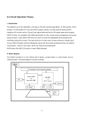
...users to offer a smart power management and power saving function. HEAD LCD module with 2 lamps(backlight) Power BD and SPK Inverter BD I . It's have dual (D-SUB and DVI) interface LCD monitor with HDCP support monitor. The block diagram is TN+Film and Normally White, 16.7M ... with VESA specification to control the adjustable items and get some information about this monitor. Introduction The X203H is a 20" W (1600x900), LCD type is shown as below. 6.2 Circuit Operation Theory I /F BD w ith HDCP support CTRL BD AC Input DVI VGA St a n d (B ase) - 57 - It's compliant with ...
...users to offer a smart power management and power saving function. HEAD LCD module with 2 lamps(backlight) Power BD and SPK Inverter BD I . It's have dual (D-SUB and DVI) interface LCD monitor with HDCP support monitor. The block diagram is TN+Film and Normally White, 16.7M ... with VESA specification to control the adjustable items and get some information about this monitor. Introduction The X203H is a 20" W (1600x900), LCD type is shown as below. 6.2 Circuit Operation Theory I /F BD w ith HDCP support CTRL BD AC Input DVI VGA St a n d (B ase) - 57 - It's compliant with ...
Acer X203H Service Guide
Page 58
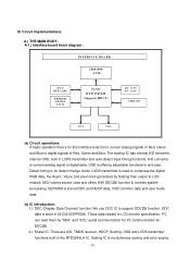
... built-in the RTD2545LH IC. PC can read them by Scaling then output to digital data. LVDS transmitter is convert analog signal to LCD module. MCU stores source code and offers H/W DDC2Bi function & controls system processing. A/D converter is used to digital signals of Red,... r RTD 2545LH (Support HDCP) D C +3.3V D C +1.8V CTRL BD DVI VGA (a) Circuit operations: A basic operation theory for this interface board is stored DDC and HDCP data, OSD common data and user mode data. (b) IC introduction: 1.) DDC (Display Data Channel) function: We use DDC IC to LCD monitor specification.
... built-in the RTD2545LH IC. PC can read them by Scaling then output to digital data. LVDS transmitter is convert analog signal to LCD module. MCU stores source code and offers H/W DDC2Bi function & controls system processing. A/D converter is used to digital signals of Red,... r RTD 2545LH (Support HDCP) D C +3.3V D C +1.8V CTRL BD DVI VGA (a) Circuit operations: A basic operation theory for this interface board is stored DDC and HDCP data, OSD common data and user mode data. (b) IC introduction: 1.) DDC (Display Data Channel) function: We use DDC IC to LCD monitor specification.

Acer X203H Service Guide
Page 59
...the introduction of 24C02 to store DVI and D-SUB EDID data. The following descriptions are 6 keys for user's control which includes "Menu", "Right", "Left", "Auto", "Empowering", and "Power". green light means DPMS on (Normal operating condition). capable of this LCD monitor; A-3.) Power board diagram: ...key: to select next and to decrease adjustment (4) "Auto" key: to perform auto adjustment and Exit key (5) "Empowering": to Open the Acer eColor Management OSD and access the scenario modes (6) "Power" key: to a highly uniform and sharp image or down scaling from 1980x1020, ...
...the introduction of 24C02 to store DVI and D-SUB EDID data. The following descriptions are 6 keys for user's control which includes "Menu", "Right", "Left", "Auto", "Empowering", and "Power". green light means DPMS on (Normal operating condition). capable of this LCD monitor; A-3.) Power board diagram: ...key: to select next and to decrease adjustment (4) "Auto" key: to perform auto adjustment and Exit key (5) "Empowering": to Open the Acer eColor Management OSD and access the scenario modes (6) "Power" key: to a highly uniform and sharp image or down scaling from 1980x1020, ...

Acer X203H Service Guide
Page 64
... MACH HEX #440*0.3" N SCRW TAP W/FL M3*10L(S3.8) ZN Color Mounting Material TORQUE (KG-CM) HOLE SIZE (MM) Screw Head Metal; Appendix 1 - Ni D-SUB;DVI 5.0±0.6 #4-40 X Connector None treadΚ 8Д10 NI Metal Have tread: ∅2.68±0.0 3Д4 3 #2 Aluminum: 4~5 3 8F.1A556.8R0 SCRW MACH PH M4*8L...
... MACH HEX #440*0.3" N SCRW TAP W/FL M3*10L(S3.8) ZN Color Mounting Material TORQUE (KG-CM) HOLE SIZE (MM) Screw Head Metal; Appendix 1 - Ni D-SUB;DVI 5.0±0.6 #4-40 X Connector None treadΚ 8Д10 NI Metal Have tread: ∅2.68±0.0 3Д4 3 #2 Aluminum: 4~5 3 8F.1A556.8R0 SCRW MACH PH M4*8L...

Acer X203H Service Guide
Page 65
...W/EXT M4*8L NI METAL METAL 5 Side M3*0.5 #2 mount:3~4 Other: 4±0.6 10±1.0 M4*0.7 #2 (B) SPECIAL SCREW TORQUE SPEC. DVI Connector SCREW TORQUE SPEC. M: MACHING SCREW. MOUNTING TORQUE MATERIAL (KG-CM) HOLE SIZE Screw (MM) Head D-SUB Connector SCREW TORQUE SPEC. ...T: TAPPING SCREW. 4. SCREW D-SUB SCREW DVI SCREW TORQUE: 1.2±0.3 (KG-CM) SCREW TORQUE : 1.2±0.3(KG-CM) - 65 - ITEM P/N DESCRIPTION *SCREW Q'TYPE AND POSITION REFERRED TO ...
...W/EXT M4*8L NI METAL METAL 5 Side M3*0.5 #2 mount:3~4 Other: 4±0.6 10±1.0 M4*0.7 #2 (B) SPECIAL SCREW TORQUE SPEC. DVI Connector SCREW TORQUE SPEC. M: MACHING SCREW. MOUNTING TORQUE MATERIAL (KG-CM) HOLE SIZE Screw (MM) Head D-SUB Connector SCREW TORQUE SPEC. ...T: TAPPING SCREW. 4. SCREW D-SUB SCREW DVI SCREW TORQUE: 1.2±0.3 (KG-CM) SCREW TORQUE : 1.2±0.3(KG-CM) - 65 - ITEM P/N DESCRIPTION *SCREW Q'TYPE AND POSITION REFERRED TO ...

