Acer X203H Service Guide
Page 13
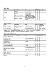
... typical lifetime of CCFL is on the condition at 7.0mA lamp current. 3.3.9 Audio performance Item Condition Preamp + Power amp (1)Output power (2)THD (@ 1W) (3)S/N ratio Speaker Driver (1)Nominal impedance (2)Rated input power (3)Frequency response (4)Output sound pressure level (5)Dimension of lamp is determined as the time at which brightness of box Audio...
... typical lifetime of CCFL is on the condition at 7.0mA lamp current. 3.3.9 Audio performance Item Condition Preamp + Power amp (1)Output power (2)THD (@ 1W) (3)S/N ratio Speaker Driver (1)Nominal impedance (2)Rated input power (3)Frequency response (4)Output sound pressure level (5)Dimension of lamp is determined as the time at which brightness of box Audio...
Acer X203H Service Guide
Page 23
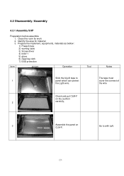
Identify the area for work 2. Go to The tape must 1 panel which can protect cover the connect of the Light-wire. the wire Check and put CLM-F on the cushion 2 carefully, 3 Assemble the panel on CLM-F. Clean the room for material 3. Prepare the implement, equipments, materials as bellow: 1) Press-fixture 2) working table 3) Screw-driver 4) knife*1 5) glove 6) cleaning cloth 7) ESD protection item picture Operation Tool Notes Stick the big Al tape to with Left. - 23 - 4.2 Disassembly /Assembly 4.2.1 Assembly SOP Preparation before assemble 1.
Identify the area for work 2. Go to The tape must 1 panel which can protect cover the connect of the Light-wire. the wire Check and put CLM-F on the cushion 2 carefully, 3 Assemble the panel on CLM-F. Clean the room for material 3. Prepare the implement, equipments, materials as bellow: 1) Press-fixture 2) working table 3) Screw-driver 4) knife*1 5) glove 6) cleaning cloth 7) ESD protection item picture Operation Tool Notes Stick the big Al tape to with Left. - 23 - 4.2 Disassembly /Assembly 4.2.1 Assembly SOP Preparation before assemble 1.
Acer X203H Service Guide
Page 24
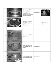
Assemble the FFC to 5 the I/F, the correct position reference on the SPS board with this Screw-driver order. 8 1 Lock 2 screws on Without the gap within the picture 6 Assemble the PCBA to fasten it. Screw-driver - 24 - the main-SHD, the 4 correct position reference on the Screw-driver picture, then the lock 4 screws to Main-SHD Lock 3 screws on the 7 PCBA board with order. Assemble the SPK to Keep the ware in.
Assemble the FFC to 5 the I/F, the correct position reference on the SPS board with this Screw-driver order. 8 1 Lock 2 screws on Without the gap within the picture 6 Assemble the PCBA to fasten it. Screw-driver - 24 - the main-SHD, the 4 correct position reference on the Screw-driver picture, then the lock 4 screws to Main-SHD Lock 3 screws on the 7 PCBA board with order. Assemble the SPK to Keep the ware in.

Acer X203H Service Guide
Page 25
9 Scan for fooling PC Card go with Screw-driver by one Al foil on the 11 right between pane land Main-BTK only for SEC panel 12 1 2 Stick two pieces of Al foil on the under between panel and Main-BTK only for SEC panel The position refer to the picture Lock screws of side on DVI. - 25 - BKT to CLM-F Stick one to 10 panel and fix the Main- Fasten the LVDS to four. 2/4,based on Attention the order 13 Main-Chassis with panel.
9 Scan for fooling PC Card go with Screw-driver by one Al foil on the 11 right between pane land Main-BTK only for SEC panel 12 1 2 Stick two pieces of Al foil on the under between panel and Main-BTK only for SEC panel The position refer to the picture Lock screws of side on DVI. - 25 - BKT to CLM-F Stick one to 10 panel and fix the Main- Fasten the LVDS to four. 2/4,based on Attention the order 13 Main-Chassis with panel.
Acer X203H Service Guide
Page 29
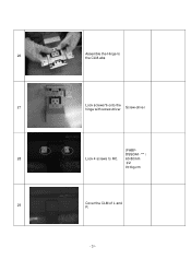
26 Assemble the Hinge to RC. 60-80mm Ϟ2 9±1kg.cm 29 Cover the CLM of L and R - 29 - DSSDA1-***α 28 Lock 4 screws to the CLM-abs 27 Lock screws*6 onto the hinge with screw-driver Screw-driver (FABF-
26 Assemble the Hinge to RC. 60-80mm Ϟ2 9±1kg.cm 29 Cover the CLM of L and R - 29 - DSSDA1-***α 28 Lock 4 screws to the CLM-abs 27 Lock screws*6 onto the hinge with screw-driver Screw-driver (FABF-
Acer X203H Service Guide
Page 30
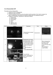
...Preparation before disassemble 1. Check the position that the monitors be placed and the quantity of bezel 4. Identify the area for disassemble 2. Prepare the implement, equipments, materials as bellow: 1) Press-fixture 2) Working table 3) Screw-driver 4) Knife*1 5) Glove 6) Cleaning cloth 7) ESD...protection item picture Operation Tool Notes Kick the board first. 1 Disassemble the stand 4 screws Screw-driver Disassembly the bezel 2 from the monitor - 30 - Clean the room for monitor 3. Right (4) parts of bezel When disassembly the bezel ,notice don't bend the C/B .man ...
...Preparation before disassemble 1. Check the position that the monitors be placed and the quantity of bezel 4. Identify the area for disassemble 2. Prepare the implement, equipments, materials as bellow: 1) Press-fixture 2) Working table 3) Screw-driver 4) Knife*1 5) Glove 6) Cleaning cloth 7) ESD...protection item picture Operation Tool Notes Kick the board first. 1 Disassemble the stand 4 screws Screw-driver Disassembly the bezel 2 from the monitor - 30 - Clean the room for monitor 3. Right (4) parts of bezel When disassembly the bezel ,notice don't bend the C/B .man ...
Acer X203H Service Guide
Page 31
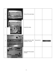
4 Tear out the acetic tape 5 Unlock the wires. 6 Disassembled the SHD Screw-driver shielding : 5 screw 7 Tear down three pieces of Al foil - 31 -
4 Tear out the acetic tape 5 Unlock the wires. 6 Disassembled the SHD Screw-driver shielding : 5 screw 7 Tear down three pieces of Al foil - 31 -
Acer X203H Service Guide
Page 32
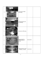
Mylar 8 Tear down the Mylar and the tap 9 Disassembled the ACsoc shielding . 10 Unlock the LVDS wires. 11 Disassembled the PCBA shielding : 5 Screw-driver screws 12 Disassembled the SPK shielding : 4 screws Screw-driver - 32 -
Mylar 8 Tear down the Mylar and the tap 9 Disassembled the ACsoc shielding . 10 Unlock the LVDS wires. 11 Disassembled the PCBA shielding : 5 Screw-driver screws 12 Disassembled the SPK shielding : 4 screws Screw-driver - 32 -


