Veriton 5500/7500 Service Guide
Page 7
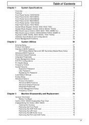
... 5500/5500G 8 Rear Panel-Veriton 5500/5500G 10 Front Panel-Veriton 7500/7500G 12 Rear Panel-Veriton 7500/7500G 14 System Block Diagram (Veriton 3500/ 5500/ 7500 16 System Block Diagram (Veriton 3500G/ 5500G/ 7500G 17 Main Board Layout (Veriton 3500/ 5500/ 7500) (S88M/ GL 18 Main Board Layout (Veriton 3500G/5500G/7500G) (S88M/ G 19 Keyboard (3500/ 3500G, 5500/ 5500G, 7500/ 7500G 21 Hardware Specifications and Configurations...
... 5500/5500G 8 Rear Panel-Veriton 5500/5500G 10 Front Panel-Veriton 7500/7500G 12 Rear Panel-Veriton 7500/7500G 14 System Block Diagram (Veriton 3500/ 5500/ 7500 16 System Block Diagram (Veriton 3500G/ 5500G/ 7500G 17 Main Board Layout (Veriton 3500/ 5500/ 7500) (S88M/ GL 18 Main Board Layout (Veriton 3500G/5500G/7500G) (S88M/ G 19 Keyboard (3500/ 3500G, 5500/ 5500G, 7500/ 7500G 21 Hardware Specifications and Configurations...

Veriton 5500/7500 Service Guide
Page 8
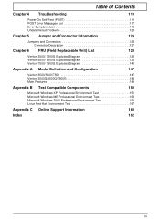
...Removing and Installing the Processor 83 Removing the System Main board 84 Removing the I/O Port Bracket 84 Veriton 5500/ 5500G Disassembly Procedure Flowchart 85 Disassembling the Veriton 5500/ 5500G 86 Open the Housing Cover 86 Removing the Front Panel 86 Removing the Empty Cover 87... 95 Removing Power Switch Cable 96 Removing the System Main Board 97 Removing the I/O Port Bracket 97 Veriton 7500/ 7500G Disassembly Procedure Flowchart 98 Disassembling the Veriton 7500/ 7500G 99 Opening the Housing 99 Removing the Front Panel 99 Removing the Modem Card 100 Removing the AGP ...
...Removing and Installing the Processor 83 Removing the System Main board 84 Removing the I/O Port Bracket 84 Veriton 5500/ 5500G Disassembly Procedure Flowchart 85 Disassembling the Veriton 5500/ 5500G 86 Open the Housing Cover 86 Removing the Front Panel 86 Removing the Empty Cover 87... 95 Removing Power Switch Cable 96 Removing the System Main Board 97 Removing the I/O Port Bracket 97 Veriton 7500/ 7500G Disassembly Procedure Flowchart 98 Disassembling the Veriton 7500/ 7500G 99 Opening the Housing 99 Removing the Front Panel 99 Removing the Modem Card 100 Removing the AGP ...
Veriton 5500/7500 Service Guide
Page 9
... and Connectors 124 Connector Description 127 Chapter 6 FRU (Field Replaceable Unit) List 128 Veriton 3500/ 3500G Exploded Diagram 129 Veriton 5500/ 5500G Exploded Diagram 135 Veriton 7500/ 7500G Exploded Diagram 141 Appendix A Model Definition and Configuration 147 Veriton 3500/5500/7500 147 Veriton 3500G/5500G/7500G 148 Main Features 149 Appendix B Test Compatible Components 150 Microsoft Windows XP Professional...
... and Connectors 124 Connector Description 127 Chapter 6 FRU (Field Replaceable Unit) List 128 Veriton 3500/ 3500G Exploded Diagram 129 Veriton 5500/ 5500G Exploded Diagram 135 Veriton 7500/ 7500G Exploded Diagram 141 Appendix A Model Definition and Configuration 147 Veriton 3500/5500/7500 147 Veriton 3500G/5500G/7500G 148 Main Features 149 Appendix B Test Compatible Components 150 Microsoft Windows XP Professional...
Veriton 5500/7500 Service Guide
Page 10
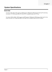
The Veriton 3500G, 5500G, 7500G supports Intel® Pentium IV (Willamette 478/Northwood) Flip Chip-Pin Grid Array 2 processor (FC-PGA2) based Micro ATX, IBM PC/AT compatible system with PCI bus. Chapter 1 System Specifications Overview The Veriton 3500, 5500, 7500 supports Intel® Pentium IV (Willamette 478/Northwood) Flip Chip-Pin Grid Array 2 processor (FC-PGA2) based Micro ATX, IBM PC/AT compatible system with PCI/ AGPbus. Chapter 1 1
The Veriton 3500G, 5500G, 7500G supports Intel® Pentium IV (Willamette 478/Northwood) Flip Chip-Pin Grid Array 2 processor (FC-PGA2) based Micro ATX, IBM PC/AT compatible system with PCI bus. Chapter 1 System Specifications Overview The Veriton 3500, 5500, 7500 supports Intel® Pentium IV (Willamette 478/Northwood) Flip Chip-Pin Grid Array 2 processor (FC-PGA2) based Micro ATX, IBM PC/AT compatible system with PCI/ AGPbus. Chapter 1 1
Veriton 5500/7500 Service Guide
Page 11
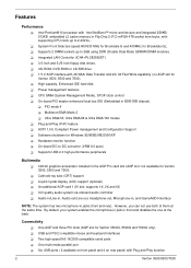
Intel Pentium® IV processor with supporting CPU clock up to -DC converter (VRM 9.0 spec) ! Software shutdown for Veriton 3500G, 5500G and 7500G only) ! On-board DC-to 2GB using DDR (Double Data Rate) SDRAM DIMM modules. ! By default, your system enables the microphone-in jack in ...ICH4+PLC82562ET). ! 3.5-inch and 5.25-inch floppy disk drives. ! CD-ROM, DVD-ROM or CD-RW drive ! 1.5 V AGP interface with Plug and Play function 2 Veriton 3500/5500/7500 However, you can not use both of them at the back. System Front Side bus speed:400/533 MHz for Brookdale G and 400MHz for...
Intel Pentium® IV processor with supporting CPU clock up to -DC converter (VRM 9.0 spec) ! Software shutdown for Veriton 3500G, 5500G and 7500G only) ! On-board DC-to 2GB using DDR (Double Data Rate) SDRAM DIMM modules. ! By default, your system enables the microphone-in jack in ...ICH4+PLC82562ET). ! 3.5-inch and 5.25-inch floppy disk drives. ! CD-ROM, DVD-ROM or CD-RW drive ! 1.5 V AGP interface with Plug and Play function 2 Veriton 3500/5500/7500 However, you can not use both of them at the back. System Front Side bus speed:400/533 MHz for Brookdale G and 400MHz for...

Veriton 5500/7500 Service Guide
Page 21
Front Panel-Veriton 7500/7500G The computer's front panel consists of the following: Label 1 2 Icon Description CD-ROM/DVD-ROM tray Stop/Eject Butto 3 Skip/Forward Button 4 Hard disk drive activity light-emitting diode (LED) 5 LAN activity LE 6 Power LED 7 Power button 8 12 CD-ROM/DVD-ROM/CD-RW LED Veriton 3500/5500/7500
Front Panel-Veriton 7500/7500G The computer's front panel consists of the following: Label 1 2 Icon Description CD-ROM/DVD-ROM tray Stop/Eject Butto 3 Skip/Forward Button 4 Hard disk drive activity light-emitting diode (LED) 5 LAN activity LE 6 Power LED 7 Power button 8 12 CD-ROM/DVD-ROM/CD-RW LED Veriton 3500/5500/7500
Veriton 5500/7500 Service Guide
Page 23
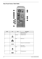
Rear Panel-Veriton 7500/7500G Label 1 2 3 4 Icon Color Burgundy Description Voltage Selector Switch Power cord socket Parallel/printer port White Network port 5 Power jack (for external speakers) 6 Power supply 7 Green PS/2 mouse port 8 Purple PS/2 keyboard port 14 Veriton 3500/5500/7500
Rear Panel-Veriton 7500/7500G Label 1 2 3 4 Icon Color Burgundy Description Voltage Selector Switch Power cord socket Parallel/printer port White Network port 5 Power jack (for external speakers) 6 Power supply 7 Green PS/2 mouse port 8 Purple PS/2 keyboard port 14 Veriton 3500/5500/7500
Veriton 5500/7500 Service Guide
Page 26
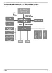
System Block Diagram (Veriton 3500G/ 5500G/ 7500G) AGP VGA AGP 4X/ 2X 1.5V signal Willamette/ Northwood Processor Scaleable Bus 3.2GB/s (4.25GB/s) Brookdale-G GMCH DDDDRR-2-26666/ /220000 2.12GB/s 266MB/s 8-Bit Hub Interface 6 USB 2.0 ports 2 ATA 100 IDE Channels LAN Connect AC97' Audio CODEC ICH4 SIO FWH PCI Slot PCI Slot PCI Slot Chapter 1 17
System Block Diagram (Veriton 3500G/ 5500G/ 7500G) AGP VGA AGP 4X/ 2X 1.5V signal Willamette/ Northwood Processor Scaleable Bus 3.2GB/s (4.25GB/s) Brookdale-G GMCH DDDDRR-2-26666/ /220000 2.12GB/s 266MB/s 8-Bit Hub Interface 6 USB 2.0 ports 2 ATA 100 IDE Channels LAN Connect AC97' Audio CODEC ICH4 SIO FWH PCI Slot PCI Slot PCI Slot Chapter 1 17
Veriton 5500/7500 Service Guide
Page 28
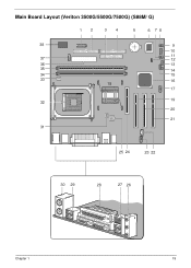
Main Board Layout (Veriton 3500G/5500G/7500G) (S88M/ G) 12 34 5 6 78 38 9 10 37 11 12 36 13 35 14 34 15 33 18 16 17 32 19 20 21 31 25 24 23 22 30 29 28 27 26 Chapter 1 19
Main Board Layout (Veriton 3500G/5500G/7500G) (S88M/ G) 12 34 5 6 78 38 9 10 37 11 12 36 13 35 14 34 15 33 18 16 17 32 19 20 21 31 25 24 23 22 30 29 28 27 26 Chapter 1 19
Veriton 5500/7500 Service Guide
Page 29
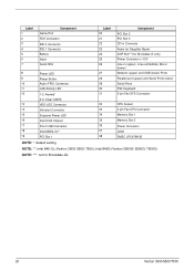
Intel 845G (Veriton 3500G/ 5500G/ 7500G) NOTE: ***: not for Brookdale G only) Power Connector (+12V Line-in (upper), Line-out(middle), Mic-in Connecto Audio for Daughter Board AGP Slot***(for Brookdale-GL 20 Veriton 3500/5500/7500 Label 1 2 3 4 5 6 7 Game Port Component FDD Connector IDE 2 Connector IDE 1 Connector Battery FWH Serial IRQ 8 Power LED 9 Power Button... 3-pin Fan CPU Connector 34 Memory Slot 1 35 Memory Slot 2 36 Power Connector 37 COM 38 SMSC LPC47M192 NOTE: *: default setting NOTE: **: Intel 845 GL (Veriton 3500/ 5500/ 7500);
Intel 845G (Veriton 3500G/ 5500G/ 7500G) NOTE: ***: not for Brookdale G only) Power Connector (+12V Line-in (upper), Line-out(middle), Mic-in Connecto Audio for Daughter Board AGP Slot***(for Brookdale-GL 20 Veriton 3500/5500/7500 Label 1 2 3 4 5 6 7 Game Port Component FDD Connector IDE 2 Connector IDE 1 Connector Battery FWH Serial IRQ 8 Power LED 9 Power Button... 3-pin Fan CPU Connector 34 Memory Slot 1 35 Memory Slot 2 36 Power Connector 37 COM 38 SMSC LPC47M192 NOTE: *: default setting NOTE: **: Intel 845 GL (Veriton 3500/ 5500/ 7500);
Veriton 5500/7500 Service Guide
Page 78
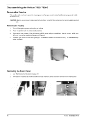
... q Hexagonal screwdriver q Plastic stick NOTE: The screws for maintenance and troubleshooting. During the disassembly process, group the screws with the corresponding components to disassemble the Veriton 3500/ 5500/ 7500 and the Veriton 3500G/ 5500G/ 7500G desktop computer for the different components vary in size. Chapter 3 70
... q Hexagonal screwdriver q Plastic stick NOTE: The screws for maintenance and troubleshooting. During the disassembly process, group the screws with the corresponding components to disassemble the Veriton 3500/ 5500/ 7500 and the Veriton 3500G/ 5500G/ 7500G desktop computer for the different components vary in size. Chapter 3 70
Veriton 5500/7500 Service Guide
Page 106
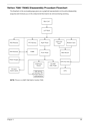
CD-RW/ DVD-ROM CPU Fan Sink CPU Chapter 3 98 Veriton 7500/ 7500G Disassembly Procedure Flowchart The flowchart on the succeeding page gives you a graphical representation on the entire disassembly sequence and instructs you on the components that need to be removed during servicing. Main Unit Left Panel FDD Module RTC Battery Right Panel AGP VGA Card Modem Card HDD Module DIMM Front Panel Main Board Power Supply USB/Audio Board Intrusion Alarm Cable LED Activity Indicators W/ Power Swtich Cable Module NOTE: There is no AGP VGA Slot for Veriton 7500.
CD-RW/ DVD-ROM CPU Fan Sink CPU Chapter 3 98 Veriton 7500/ 7500G Disassembly Procedure Flowchart The flowchart on the succeeding page gives you a graphical representation on the entire disassembly sequence and instructs you on the components that need to be removed during servicing. Main Unit Left Panel FDD Module RTC Battery Right Panel AGP VGA Card Modem Card HDD Module DIMM Front Panel Main Board Power Supply USB/Audio Board Intrusion Alarm Cable LED Activity Indicators W/ Power Swtich Cable Module NOTE: There is no AGP VGA Slot for Veriton 7500.
Veriton 5500/7500 Service Guide
Page 107
... on a flat, steady surface. 3. Slide the right panel out and then gently pull it outward to detach it from the housing . 99 Veriton 3500/5500/7500 Removing the Housing 1. CAUTION: Before you proceed, make sure that holds the front panel and then remove it from the housing. Release the 6... latches as shown below that you need them when replacing the panel of the right panel and left panel. . Disassembling the Veriton 7500/ 7500G Opening the Housing This section tells you how to open the housing cover when you have turned off the system power and unplug all peripherals...
... on a flat, steady surface. 3. Slide the right panel out and then gently pull it outward to detach it from the housing . 99 Veriton 3500/5500/7500 Removing the Housing 1. CAUTION: Before you proceed, make sure that holds the front panel and then remove it from the housing. Release the 6... latches as shown below that you need them when replacing the panel of the right panel and left panel. . Disassembling the Veriton 7500/ 7500G Opening the Housing This section tells you how to open the housing cover when you have turned off the system power and unplug all peripherals...
Veriton 5500/7500 Service Guide
Page 118
Chapter 4 Troubleshooting This chapter provides troubleshooting information for the Veriton 3500/5500/7500, and the Veriton 3500G/ 5500G/7500G ! Power-On Self-Test (POST) ! Undetermined Problems Chapter 4 110 Index of Error Symptoms ! Index of Error Message !
Chapter 4 Troubleshooting This chapter provides troubleshooting information for the Veriton 3500/5500/7500, and the Veriton 3500G/ 5500G/7500G ! Power-On Self-Test (POST) ! Undetermined Problems Chapter 4 110 Index of Error Symptoms ! Index of Error Message !
Veriton 5500/7500 Service Guide
Page 135
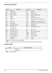
Intel 845G (Veriton 3500G/ 5500G/ 7500G) Jumper Setting Jumper JP2 1-2 Normal* 2-3 Clear CMOS NOTE: *: Default Settings. NOTE: *: Intel 845 GL (Veriton 3500/ 5500/ 7500); Function and settings 127 Veriton 3500/5500/7500 Connector Description Label CN6 CN9 CN12 CN13 BT1 U24 CN23 Game Port Component FDD Connector IDE 2 Connector IDE 1 Connector Battery FWH Serial IRQ CN26 CN21...
Intel 845G (Veriton 3500G/ 5500G/ 7500G) Jumper Setting Jumper JP2 1-2 Normal* 2-3 Clear CMOS NOTE: *: Default Settings. NOTE: *: Intel 845 GL (Veriton 3500/ 5500/ 7500); Function and settings 127 Veriton 3500/5500/7500 Connector Description Label CN6 CN9 CN12 CN13 BT1 U24 CN23 Game Port Component FDD Connector IDE 2 Connector IDE 1 Connector Battery FWH Serial IRQ CN26 CN21...

Veriton 5500/7500 Service Guide
Page 136
... number code to those given in Chapter 3 for RMA (Return Merchandise Authorization). IMPORTANT: Please note WHEN ORDERING FRU PARTS, that Acer Corporation sells only the parts listed in the following table. Please be noted in global configurations of this chapter whenever ordering for parts... purpose, Acer Corporation does not provide these parts. NOTE: The number indicates the location shown on exploded diagram or "NS" indicates "Not shown" on it will not be reminded that though some parts are disassembled in the FRU list of Veriton 3500/ 3500G, 5500/ 5500G, 7500/ 7500G. Chapter...
... number code to those given in Chapter 3 for RMA (Return Merchandise Authorization). IMPORTANT: Please note WHEN ORDERING FRU PARTS, that Acer Corporation sells only the parts listed in the following table. Please be noted in global configurations of this chapter whenever ordering for parts... purpose, Acer Corporation does not provide these parts. NOTE: The number indicates the location shown on exploded diagram or "NS" indicates "Not shown" on it will not be reminded that though some parts are disassembled in the FRU list of Veriton 3500/ 3500G, 5500/ 5500G, 7500/ 7500G. Chapter...
Veriton 5500/7500 Service Guide
Page 156
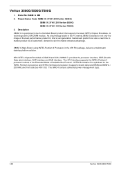
... INTEL Northwood processor. Project Name/ Code: S88M 91.31V01.301(Veriton 3500G) S88M 91.31V01.201(Veriton 5500G) S88M 91.31V01.101(Veriton 7500G) 3. INTEL Brookdale-G is positioned to win the market entrance advantage. The GMCH contains advanced power management logic. 148 Veriton 3500/5500/7500 It supports double data rate DRAM at 266MHz./ 200 MHz...
... INTEL Northwood processor. Project Name/ Code: S88M 91.31V01.301(Veriton 3500G) S88M 91.31V01.201(Veriton 5500G) S88M 91.31V01.101(Veriton 7500G) 3. INTEL Brookdale-G is positioned to win the market entrance advantage. The GMCH contains advanced power management logic. 148 Veriton 3500/5500/7500 It supports double data rate DRAM at 266MHz./ 200 MHz...
Veriton 7500
Page 2
Record the model number, serial number, purchase date, and place of Acer Inc. The serial number and model number are recorded on the label affixed to your unit should include the ...Acer and the Acer Logo are used herein for identification purposes only and belong to the contents hereof and specifically disclaims the implied warranties of such revision or changes. This company makes no representations or warranties, either expressed or implied, with respect to their respective companies. All correspondence concerning your computer. Veriton 7500 series (Veriton 7500/Veriton 7500G...
Record the model number, serial number, purchase date, and place of Acer Inc. The serial number and model number are recorded on the label affixed to your unit should include the ...Acer and the Acer Logo are used herein for identification purposes only and belong to the contents hereof and specifically disclaims the implied warranties of such revision or changes. This company makes no representations or warranties, either expressed or implied, with respect to their respective companies. All correspondence concerning your computer. Veriton 7500 series (Veriton 7500/Veriton 7500G...
Veriton 7500
Page 67
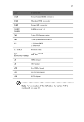
57 Label Component CN24 Power/Suspend LED connector CN25 Standard FPIO connector CN26 Power LED connector DIMM 1 DIMM 2 DIMM sockets 1-2 FN1 3-pin CPU fan connector FN2 3-pin system fan connector JP2 1-2 Clear CMOS 2-3 Normal SL1 to SL3 PCI slots 1 to 3 SLT1 AGP slot see note (for Veriton 7500G) U3 SMSC chipset U8 CPU socket U14 Intel 845 chipset U21 Intel ICH4 chipset U24 BIOS chipset Note: For the location of the AGP slot on the Veriton 7500G mainboard, see page 55.
57 Label Component CN24 Power/Suspend LED connector CN25 Standard FPIO connector CN26 Power LED connector DIMM 1 DIMM 2 DIMM sockets 1-2 FN1 3-pin CPU fan connector FN2 3-pin system fan connector JP2 1-2 Clear CMOS 2-3 Normal SL1 to SL3 PCI slots 1 to 3 SLT1 AGP slot see note (for Veriton 7500G) U3 SMSC chipset U8 CPU socket U14 Intel 845 chipset U21 Intel ICH4 chipset U24 BIOS chipset Note: For the location of the AGP slot on the Veriton 7500G mainboard, see page 55.

Veriton 7500
Page 93
... lock key 15 volume control/mute knob 15 Windows logo key 15 L lock keys Caps Lock 16 Num Lock 16 Scroll Lock 16 M mainboard Veriton 7500 54 Veriton 7500G 55 mouse 20 buttons 20 clicking 20 double-click 20 ratchet wheel 20 multimedia key forward 18 play/pause 18 stop 18 R rear panel 13...
... lock key 15 volume control/mute knob 15 Windows logo key 15 L lock keys Caps Lock 16 Num Lock 16 Scroll Lock 16 M mainboard Veriton 7500 54 Veriton 7500G 55 mouse 20 buttons 20 clicking 20 double-click 20 ratchet wheel 20 multimedia key forward 18 play/pause 18 stop 18 R rear panel 13...


