Veriton 5500/7500 Service Guide
Page 7
.../3500G 6 Front Panel-Veriron 5500/5500G 8 Rear Panel-Veriton 5500/5500G 10 Front Panel-Veriton 7500/7500G 12 Rear Panel-Veriton 7500/7500G 14 System Block Diagram (Veriton 3500/ 5500/ 7500 16 System Block Diagram (Veriton 3500G/ 5500G/ 7500G 17 Main Board Layout (Veriton 3500/ 5500/ 7500) (S88M/ GL 18 Main Board Layout (Veriton 3500G/5500G/7500G) (S88M/ G 19 Keyboard (3500...
.../3500G 6 Front Panel-Veriron 5500/5500G 8 Rear Panel-Veriton 5500/5500G 10 Front Panel-Veriton 7500/7500G 12 Rear Panel-Veriton 7500/7500G 14 System Block Diagram (Veriton 3500/ 5500/ 7500 16 System Block Diagram (Veriton 3500G/ 5500G/ 7500G 17 Main Board Layout (Veriton 3500/ 5500/ 7500) (S88M/ GL 18 Main Board Layout (Veriton 3500G/5500G/7500G) (S88M/ G 19 Keyboard (3500...

Veriton 5500/7500 Service Guide
Page 8
... Module 95 Removing Power Switch Cable 96 Removing the System Main Board 97 Removing the I/O Port Bracket 97 Veriton 7500/ 7500G Disassembly Procedure Flowchart 98 Disassembling the Veriton 7500/ 7500G 99 Opening the Housing 99 Removing the Front Panel 99 Removing the Modem Card 100 Removing the AGP... VGA Card 100 Removing the USB/ Audio Board 101 Removing the DVD-ROM and CD-RW Drive 102 Removing the ...
... Module 95 Removing Power Switch Cable 96 Removing the System Main Board 97 Removing the I/O Port Bracket 97 Veriton 7500/ 7500G Disassembly Procedure Flowchart 98 Disassembling the Veriton 7500/ 7500G 99 Opening the Housing 99 Removing the Front Panel 99 Removing the Modem Card 100 Removing the AGP... VGA Card 100 Removing the USB/ Audio Board 101 Removing the DVD-ROM and CD-RW Drive 102 Removing the ...
Veriton 5500/7500 Service Guide
Page 11
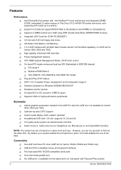
...1.5V slot, supports 1X, 2X and 4X ! 3-D quality audio system via onboard audio controller ! However, you can not use both of them at the back. System Front Side bus speed:400/533 MHz for Brookdale G and 400MHz for Veriton 3500, 5500 and 7500). ! High capacity, Enhanced-IDE hard disk ! PIO mode ... Power management features ! By default, your system enables the microphone-in jack in the AGP Pro card slot (AGP slot: not available for Veriton 3500, 5500 and 7500) ! USB and PS/2 compatible mouse and keyboard interfaces ! CD-ROM, DVD-ROM or CD-RW drive ! 1.5 V AGP interface with Plug...
...1.5V slot, supports 1X, 2X and 4X ! 3-D quality audio system via onboard audio controller ! However, you can not use both of them at the back. System Front Side bus speed:400/533 MHz for Brookdale G and 400MHz for Veriton 3500, 5500 and 7500). ! High capacity, Enhanced-IDE hard disk ! PIO mode ... Power management features ! By default, your system enables the microphone-in jack in the AGP Pro card slot (AGP slot: not available for Veriton 3500, 5500 and 7500) ! USB and PS/2 compatible mouse and keyboard interfaces ! CD-ROM, DVD-ROM or CD-RW drive ! 1.5 V AGP interface with Plug...
Veriton 5500/7500 Service Guide
Page 16
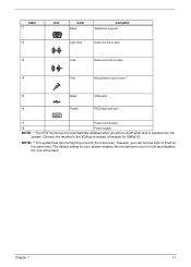
.... Label 12 13 14 15 Icon Color Purple Description PS/2 keyboard port Black Pink USB ports Microphone-in port (rear)** Lime Audio-out/Line-out jack 16 Light blue Audio-in/Line-in front and disables the one at the same time. However, you can not use both of them at the...
.... Label 12 13 14 15 Icon Color Purple Description PS/2 keyboard port Black Pink USB ports Microphone-in port (rear)** Lime Audio-out/Line-out jack 16 Light blue Audio-in/Line-in front and disables the one at the same time. However, you can not use both of them at the...
Veriton 5500/7500 Service Guide
Page 20
.... However, you can not use both of them at the back. Chapter 1 11 Label 11 12 Icon Color Black escription Telephone line port Light blue Audio-in/Line-in jack 13 Lime Audio-out/Line-out jack 14 Pink Microphone-in ports (front and rear).
.... However, you can not use both of them at the back. Chapter 1 11 Label 11 12 Icon Color Black escription Telephone line port Light blue Audio-in/Line-in jack 13 Lime Audio-out/Line-out jack 14 Pink Microphone-in ports (front and rear).
Veriton 5500/7500 Service Guide
Page 24
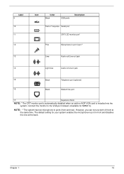
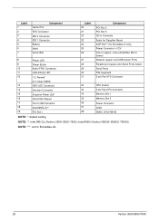
... Icon Color Black USB ports Description Teal or Turquoise Serial port CRT/LCD monitor port* Pink Microphone-in port (rear)** 13 Lime Audio-out/Line-out jack 14 Light blue Audio-in/Line-in jack 15 Black Telephone port (optional) 16 Black Modem line port 17 Expansion Slots NOTE: * The CRT monitor...
... Icon Color Black USB ports Description Teal or Turquoise Serial port CRT/LCD monitor port* Pink Microphone-in port (rear)** 13 Lime Audio-out/Line-out jack 14 Light blue Audio-in/Line-in jack 15 Black Telephone port (optional) 16 Black Modem line port 17 Expansion Slots NOTE: * The CRT monitor...
Veriton 5500/7500 Service Guide
Page 25
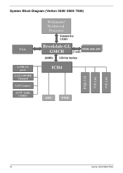
System Block Diagram (Veriton 3500/ 5500/ 7500) VGA 6 USB 2.0 ports 2 ATA 100 IDE Channels LAN Connect AC97' Audio CODEC Willamette/ Northwood Processor Scaleable Bus 3.2GB/s Brookdale-GL GMCH 2.12GB/s DDDDRR-2-26666/ /220000 266MB/s 8-Bit Hub Interface ICH4 SIO FWH PCI Slot PCI Slot PCI Slot 16 Veriton 3500/5500/7500
System Block Diagram (Veriton 3500/ 5500/ 7500) VGA 6 USB 2.0 ports 2 ATA 100 IDE Channels LAN Connect AC97' Audio CODEC Willamette/ Northwood Processor Scaleable Bus 3.2GB/s Brookdale-GL GMCH 2.12GB/s DDDDRR-2-26666/ /220000 266MB/s 8-Bit Hub Interface ICH4 SIO FWH PCI Slot PCI Slot PCI Slot 16 Veriton 3500/5500/7500
Veriton 5500/7500 Service Guide
Page 26
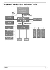
System Block Diagram (Veriton 3500G/ 5500G/ 7500G) AGP VGA AGP 4X/ 2X 1.5V signal Willamette/ Northwood Processor Scaleable Bus 3.2GB/s (4.25GB/s) Brookdale-G GMCH DDDDRR-2-26666/ /220000 2.12GB/s 266MB/s 8-Bit Hub Interface 6 USB 2.0 ports 2 ATA 100 IDE Channels LAN Connect AC97' Audio CODEC ICH4 SIO FWH PCI Slot PCI Slot PCI Slot Chapter 1 17
System Block Diagram (Veriton 3500G/ 5500G/ 7500G) AGP VGA AGP 4X/ 2X 1.5V signal Willamette/ Northwood Processor Scaleable Bus 3.2GB/s (4.25GB/s) Brookdale-G GMCH DDDDRR-2-26666/ /220000 2.12GB/s 266MB/s 8-Bit Hub Interface 6 USB 2.0 ports 2 ATA 100 IDE Channels LAN Connect AC97' Audio CODEC ICH4 SIO FWH PCI Slot PCI Slot PCI Slot Chapter 1 17
Veriton 5500/7500 Service Guide
Page 29
... (+12V Line-in (upper), Line-out(middle), Mic-in Connecto Audio for Daughter Board AGP Slot***(for Brookdale-GL 20 Veriton 3500/5500/7500 Label 1 2 3 4 5 6 7 Game Port Component FDD Connector IDE 2 Connector IDE 1 Connector Battery FWH Serial IRQ 8 Power LED 9 Power Button 10 Audio FPIO Connector 11 LAN Activity LED 12 1-2: Normal* 2-3: Clear CMOS... 3-pin Fan CPU Connector 34 Memory Slot 1 35 Memory Slot 2 36 Power Connector 37 COM 38 SMSC LPC47M192 NOTE: *: default setting NOTE: **: Intel 845 GL (Veriton 3500/ 5500/ 7500);
... (+12V Line-in (upper), Line-out(middle), Mic-in Connecto Audio for Daughter Board AGP Slot***(for Brookdale-GL 20 Veriton 3500/5500/7500 Label 1 2 3 4 5 6 7 Game Port Component FDD Connector IDE 2 Connector IDE 1 Connector Battery FWH Serial IRQ 8 Power LED 9 Power Button 10 Audio FPIO Connector 11 LAN Activity LED 12 1-2: Normal* 2-3: Clear CMOS... 3-pin Fan CPU Connector 34 Memory Slot 1 35 Memory Slot 2 36 Power Connector 37 COM 38 SMSC LPC47M192 NOTE: *: default setting NOTE: **: Intel 845 GL (Veriton 3500/ 5500/ 7500);

Veriton 5500/7500 Service Guide
Page 31
... or • Forward Button : press to skip forward to the next track or file and start playing the audio track or video file. dled with your system. • Web brows : er launches the browser application that came bun- To configure the settings of three ... mute and sound. 10 Multimedia keys Allow you directly access a URL (Web site) or launch any programs, files, or applications in your desktop. 22 Veriton 3500/5500/7500 ous track or file and start playing. 11 Internet/Suspend keys Consist of each key, right click on the Magic Keyboard icon located on...
... or • Forward Button : press to skip forward to the next track or file and start playing the audio track or video file. dled with your system. • Web brows : er launches the browser application that came bun- To configure the settings of three ... mute and sound. 10 Multimedia keys Allow you directly access a URL (Web site) or launch any programs, files, or applications in your desktop. 22 Veriton 3500/5500/7500 ous track or file and start playing. 11 Internet/Suspend keys Consist of each key, right click on the Magic Keyboard icon located on...

Veriton 5500/7500 Service Guide
Page 35
... Stereo 20 bits AC'97 2.1 compliant Sound Blaster Pro compatible Mixed digital and analog high performance chip Enhanced stereo full duplex operation High performance PCI audio accelerator High-Quality ESFM music synthesize MPU-401(UART mode) interface for wavetable synthesizers and MIDI devices Integrated game port Meets PC 97/PC98 and... (max) Startup (peak Maximum Seeking (RMS) Voltage tolerance (V 26 Panasonic JU-256A047P Specification 1.44 MB 80 160 300 2 MFM/FM 5V 290mA 710mA +5V +/- 10% Veriton 3500/5500/7500
... Stereo 20 bits AC'97 2.1 compliant Sound Blaster Pro compatible Mixed digital and analog high performance chip Enhanced stereo full duplex operation High performance PCI audio accelerator High-Quality ESFM music synthesize MPU-401(UART mode) interface for wavetable synthesizers and MIDI devices Integrated game port Meets PC 97/PC98 and... (max) Startup (peak Maximum Seeking (RMS) Voltage tolerance (V 26 Panasonic JU-256A047P Specification 1.44 MB 80 160 300 2 MFM/FM 5V 290mA 710mA +5V +/- 10% Veriton 3500/5500/7500
Veriton 5500/7500 Service Guide
Page 39
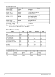
.... Onboard Device ID & IRQ Map Device Intel 845G MCH P2P (Func.0) ICH4 (LPC) (Func.1) ICH4 (IDE) (Func.2) ICH4(USB) (Func.3) ICH4 (SMBUS (Func.5) ICH4 (AC97 Audio) PCI Slot 1 PCI Slot 2 PCI Slot 3 AD# AD11 AD30 AD31 AD31 AD31 AD31 AD31 AD16 AD17 AD21 IDSEL 00h 13h 14h 14h 14h 14h 14h... IRQ Routing Map PCI INTX# PCI 1 PCI 2 PCI 3 INT Route 1 Route 4 Route 3 INTB Route 2 Route 1 Route 4 INTC Route 3 Route 2 Route 1 INTD Route 4 Route 3 Route 2 30 Veriton 3500/5500/7500
.... Onboard Device ID & IRQ Map Device Intel 845G MCH P2P (Func.0) ICH4 (LPC) (Func.1) ICH4 (IDE) (Func.2) ICH4(USB) (Func.3) ICH4 (SMBUS (Func.5) ICH4 (AC97 Audio) PCI Slot 1 PCI Slot 2 PCI Slot 3 AD# AD11 AD30 AD31 AD31 AD31 AD31 AD31 AD16 AD17 AD21 IDSEL 00h 13h 14h 14h 14h 14h 14h... IRQ Routing Map PCI INTX# PCI 1 PCI 2 PCI 3 INT Route 1 Route 4 Route 3 INTB Route 2 Route 1 Route 4 INTC Route 3 Route 2 Route 1 INTD Route 4 Route 3 Route 2 30 Veriton 3500/5500/7500
Veriton 5500/7500 Service Guide
Page 41
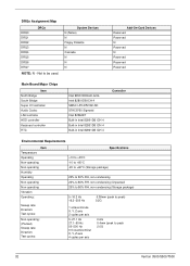
... N (Notes) N Floppy Diskette N Cascade N N N Add-On-Card Devices Reserved Reserved N Reserved N Reserved Reserved Reserved Main Board Major Chips Item North Bridge South Bridge Super I/O controller Audio Codec LAN controlle HDD controller Keyboard controller RTC Intel BROOKDALE-G/GL Intel 82801DB ICH 4 SMSC LPC47M192-NC STAC9750 Sigmatel Intel 82562ET Built-in Intel 82801DB... 5~27.1 Hz 27.1~50 Hz 50~500 Hz 0.5 coactive/minut X, Y, Z axis 4 cycles per axis 0.6G 0.4mm (peak to be used. Not to peak 2.0G 32 Veriton 3500/5500/7500
... N (Notes) N Floppy Diskette N Cascade N N N Add-On-Card Devices Reserved Reserved N Reserved N Reserved Reserved Reserved Main Board Major Chips Item North Bridge South Bridge Super I/O controller Audio Codec LAN controlle HDD controller Keyboard controller RTC Intel BROOKDALE-G/GL Intel 82801DB ICH 4 SMSC LPC47M192-NC STAC9750 Sigmatel Intel 82562ET Built-in Intel 82801DB... 5~27.1 Hz 27.1~50 Hz 50~500 Hz 0.5 coactive/minut X, Y, Z axis 4 cycles per axis 0.6G 0.4mm (peak to be used. Not to peak 2.0G 32 Veriton 3500/5500/7500

Veriton 5500/7500 Service Guide
Page 54
...during POST or after boot if you don't have a USB driver in the operating system. Enabled Disabled Enabling the on-die AC97 Audio if no add-on PCI Audio Auto device. Button only (press the power button only) Any Key (press any key on the PS2 keyboard or press the ...IDE Primary Master UDMA IDE Primary Slave UDMA IDE Secondary Master UDMA IDE Secondary Slave UDMA USB controller USB Keyboard Support USB Mouse Support AC97 Audio Onboard LAN Controller Init Display First IDE HDD Block Mode Power on Function Onboard FDC Controller Onboard Serial Port 1 Description Options Setting these ...
...during POST or after boot if you don't have a USB driver in the operating system. Enabled Disabled Enabling the on-die AC97 Audio if no add-on PCI Audio Auto device. Button only (press the power button only) Any Key (press any key on the PS2 keyboard or press the ...IDE Primary Master UDMA IDE Primary Slave UDMA IDE Secondary Master UDMA IDE Secondary Slave UDMA USB controller USB Keyboard Support USB Mouse Support AC97 Audio Onboard LAN Controller Init Display First IDE HDD Block Mode Power on Function Onboard FDC Controller Onboard Serial Port 1 Description Options Setting these ...
Veriton 5500/7500 Service Guide
Page 80
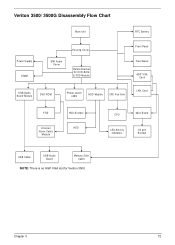
Veriton 3500/ 3500G Disassembly Flow Chart Main Unit RTC Battery Power Supply DIMM EMI Audio Cover Housing Cover Rotate Bracket W/ DVD-ROM & FDD Module Front Panel Front Bezel AGP VGA Card USB/Audio Board Module DVD-ROM Power switch cable HDD Module CPU Fan Sink LAN Card FDD Intrusion Alarm Cable Module HDD Bracket HDD Main Board CPU LED Activity Indicators I/O port Bracket USB Cable USB/Audio Board Memory Stick Cable NOTE: There is no AGP VGA slot for Veriton 3500. Chapter 3 72
Veriton 3500/ 3500G Disassembly Flow Chart Main Unit RTC Battery Power Supply DIMM EMI Audio Cover Housing Cover Rotate Bracket W/ DVD-ROM & FDD Module Front Panel Front Bezel AGP VGA Card USB/Audio Board Module DVD-ROM Power switch cable HDD Module CPU Fan Sink LAN Card FDD Intrusion Alarm Cable Module HDD Bracket HDD Main Board CPU LED Activity Indicators I/O port Bracket USB Cable USB/Audio Board Memory Stick Cable NOTE: There is no AGP VGA slot for Veriton 3500. Chapter 3 72
Veriton 5500/7500 Service Guide
Page 83
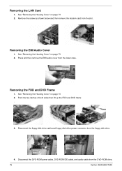
... the floppy disk drive cable and floppy disk drive power connector from the DVD-ROM drive. 75 Veriton 3500/5500/7500 Removing the LAN Card 1. Disconnect the DVD-ROM power cable, DVD-ROM IDE cable, and audio cable from the floppy disk drive. 4. Removing the FDD and DVD Frame 1. See "Removing the Housing... up the FDD and DVD frame . 3. Remove the screw as shown below and then remove the modem card from the lower case. Removing the EMI Audio Cover 1. Press and then remove the EMI audio cover from the slot. See "Removing the Housing Cover" on page 73 2.
... the floppy disk drive cable and floppy disk drive power connector from the DVD-ROM drive. 75 Veriton 3500/5500/7500 Removing the LAN Card 1. Disconnect the DVD-ROM power cable, DVD-ROM IDE cable, and audio cable from the floppy disk drive. 4. Removing the FDD and DVD Frame 1. See "Removing the Housing... up the FDD and DVD frame . 3. Remove the screw as shown below and then remove the modem card from the lower case. Removing the EMI Audio Cover 1. Press and then remove the EMI audio cover from the slot. See "Removing the Housing Cover" on page 73 2.
Veriton 5500/7500 Service Guide
Page 87
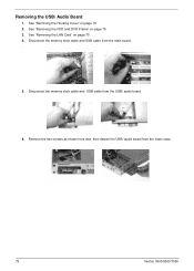
See "Removing the FDD and DVD Frame" on page 75 4. See "Removing the LAN Card" on page 75 3. See "Removing the Housing Cover" on page 73 2. Disconnect the memory stick cable and USB cable from the lower case. 79 Veriton 3500/5500/7500 Remove the two screws as shown here and then detach the USB/ audio board from the USB/ audio board. 6. Disconnect the memory stick cable and USB cable from the main board. . 5. Removing the USB/ Audio Board 1.
See "Removing the FDD and DVD Frame" on page 75 4. See "Removing the LAN Card" on page 75 3. See "Removing the Housing Cover" on page 73 2. Disconnect the memory stick cable and USB cable from the lower case. 79 Veriton 3500/5500/7500 Remove the two screws as shown here and then detach the USB/ audio board from the USB/ audio board. 6. Disconnect the memory stick cable and USB cable from the main board. . 5. Removing the USB/ Audio Board 1.
Veriton 5500/7500 Service Guide
Page 93
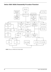
Veriton 5500/ 5500G Disassembly Procedure Flowchart LED Activity Indicators Intrusion Alarm Cable Module Main Unit Housing Cover Front Panel W/ Empty Cover Power Switch Cable Front Panel Empter Cover Dummy Link Bar AGP VGA Card Modem Card USB/Audio Board Module CPU Fan Sink DIMM Main Board Memory Stick Cable CPU Link Bar I/O Port Bracket USB/ Audio Board RTC Battery USB Cable HDD FDD Power Supply CD-ROM DVD-ROM NOTE: There is no AGP slot for Veriton 5500. 85 Veriton 3500/5500/7500
Veriton 5500/ 5500G Disassembly Procedure Flowchart LED Activity Indicators Intrusion Alarm Cable Module Main Unit Housing Cover Front Panel W/ Empty Cover Power Switch Cable Front Panel Empter Cover Dummy Link Bar AGP VGA Card Modem Card USB/Audio Board Module CPU Fan Sink DIMM Main Board Memory Stick Cable CPU Link Bar I/O Port Bracket USB/ Audio Board RTC Battery USB Cable HDD FDD Power Supply CD-ROM DVD-ROM NOTE: There is no AGP slot for Veriton 5500. 85 Veriton 3500/5500/7500
Veriton 5500/7500 Service Guide
Page 96
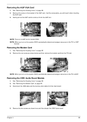
...detects and assigns resources to the PCI orAGP. Remove the one screw as shown here and then detach the USB/ Audio board Chapter 3 88 NOTE: When you turn on page 88 3. Disconnect the USB cable and the memory stick ...resources to remove it when inserting the AGP card. 3. See "Removing the Housing Cover" on page 86 2. Removing the USB/ Audio Board Module 1. Removing the Modem Card 1. Removing the AGP VGA Card 1. See "Removing the Housing Cover" on page 86 ...to the PCI or AGP devices. NOTE: There is no AGP slot for Veriton 5500. See "Removing the Housing Cover" on page 86 2.
...detects and assigns resources to the PCI orAGP. Remove the one screw as shown here and then detach the USB/ Audio board Chapter 3 88 NOTE: When you turn on page 88 3. Disconnect the USB cable and the memory stick ...resources to remove it when inserting the AGP card. 3. See "Removing the Housing Cover" on page 86 2. Removing the USB/ Audio Board Module 1. Removing the Modem Card 1. Removing the AGP VGA Card 1. See "Removing the Housing Cover" on page 86 ...to the PCI or AGP devices. NOTE: There is no AGP slot for Veriton 5500. See "Removing the Housing Cover" on page 86 2.
Veriton 5500/7500 Service Guide
Page 97
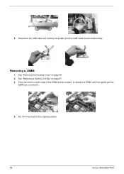
See "Removing the Housing Cover" on page 87 3. Disconnect the USB cable and memory stick cable from the USB/ Audio board consecutively. Press the levers on both sides of the DIMM socket outward to release the DIMM, and then gently pull the DIMM out to the original position. 89 Veriton 3500/5500/7500 Removing a DIMM 1. See "Removing a Dummy Link Bar" on page 86 2. Put the levers back to remove it. 4. . 5.
See "Removing the Housing Cover" on page 87 3. Disconnect the USB cable and memory stick cable from the USB/ Audio board consecutively. Press the levers on both sides of the DIMM socket outward to release the DIMM, and then gently pull the DIMM out to the original position. 89 Veriton 3500/5500/7500 Removing a DIMM 1. See "Removing a Dummy Link Bar" on page 86 2. Put the levers back to remove it. 4. . 5.


