User Manual
Page 3
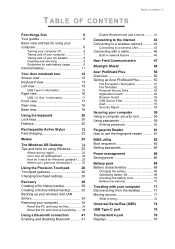
... your computer 7 Taking care of your AC adapter 8 Cleaning and servicing 8 Guidelines for safe battery usage 8 Internal battery 11 Your Acer notebook tour 12 Screen view 12 Keyboard view 13 Left view 15 USB Type-C information 16 Right view 16 USB 3.2 Gen 1 information... Built-in network feature 46 Near Field Communication 47 Bluelight Shield 48 Acer ProShield Plus 50 Overview 50 Setting up Acer ProShield Plus 50 File Encryption / Decryption 51 File Shredder 52 Personal Secure Drive 52 Application Guard 54 Browser Guard 55 USB Device Filter 56 Alert 57...
... your computer 7 Taking care of your AC adapter 8 Cleaning and servicing 8 Guidelines for safe battery usage 8 Internal battery 11 Your Acer notebook tour 12 Screen view 12 Keyboard view 13 Left view 15 USB Type-C information 16 Right view 16 USB 3.2 Gen 1 information... Built-in network feature 46 Near Field Communication 47 Bluelight Shield 48 Acer ProShield Plus 50 Overview 50 Setting up Acer ProShield Plus 50 File Encryption / Decryption 51 File Shredder 52 Personal Secure Drive 52 Application Guard 54 Browser Guard 55 USB Device Filter 56 Alert 57...

User Manual
Page 51
You can select folders and files for encryption or decryption. Acer ProShield Plus - 51 Set up Windows Hello to guess. It is advisable to use a combination of the following authentications to access the Acer ProShield Plus and decrypt encrypted files. • Face • Fingerprint • PIN File Encryption / Decryption Here you can use words...
You can select folders and files for encryption or decryption. Acer ProShield Plus - 51 Set up Windows Hello to guess. It is advisable to use a combination of the following authentications to access the Acer ProShield Plus and decrypt encrypted files. • Face • Fingerprint • PIN File Encryption / Decryption Here you can use words...

Lifecycle Extension Guide
Page 40
Figure 1-51. Push down both hinges (Figure 1-51). Figure 1-52. LCD Bezel Removal 1-38 Disassembly Procedures LCD Bezel Removal (Clamshell Model) 0 Prerequisite: LCD Module Removal 1. LCD Bezel Removal 2. Pry the LCD bezel from the bottom side to release the latches (Figure 1-52).
Figure 1-51. Push down both hinges (Figure 1-51). Figure 1-52. LCD Bezel Removal 1-38 Disassembly Procedures LCD Bezel Removal (Clamshell Model) 0 Prerequisite: LCD Module Removal 1. LCD Bezel Removal 2. Pry the LCD bezel from the bottom side to release the latches (Figure 1-52).

Lifecycle Extension Guide
Page 53
1 2 4 3 5 6 7 Figure 1-65. LCD Assembly Exploded Diagram (Clamshell Model) No. Description 1 LCD Bezel 2 LCD Panel 3 eDP Cable (includes LCD panel cable and camera cable) 4 Microphone Rubbers 5 Camera Module 6 LCD Hinge L LCD Hinge R 7 LCD Cover Exploded Diagrams 1-51 LCD Assembly Exploded Diagram (Clamshell Model) Table 1-4.
1 2 4 3 5 6 7 Figure 1-65. LCD Assembly Exploded Diagram (Clamshell Model) No. Description 1 LCD Bezel 2 LCD Panel 3 eDP Cable (includes LCD panel cable and camera cable) 4 Microphone Rubbers 5 Camera Module 6 LCD Hinge L LCD Hinge R 7 LCD Cover Exploded Diagrams 1-51 LCD Assembly Exploded Diagram (Clamshell Model) Table 1-4.