User Manual
Page 3
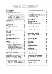
...Taking care of your computer 7 Taking care of your AC adapter 8 Cleaning and servicing 8 Guidelines for safe battery usage 8 Internal battery 11 Your Acer notebook tour 12 Screen view 12 Keyboard view 13 Left view 15 USB Type-C information 16 Right view 16 USB 3.2 Gen 1 information 17 Front ...view 17 Rear view 18 Base view 18 Using the keyboard 20 Lock keys 20 Hotkeys 20 Rechargeable Active Stylus 22 Fast-charging 22 Modes 23 The Windows OS Desktop 24 Tips and hints for using Windows.......... 25 Where are my apps 25 Can I...
...Taking care of your computer 7 Taking care of your AC adapter 8 Cleaning and servicing 8 Guidelines for safe battery usage 8 Internal battery 11 Your Acer notebook tour 12 Screen view 12 Keyboard view 13 Left view 15 USB Type-C information 16 Right view 16 USB 3.2 Gen 1 information 17 Front ...view 17 Rear view 18 Base view 18 Using the keyboard 20 Lock keys 20 Hotkeys 20 Rechargeable Active Stylus 22 Fast-charging 22 Modes 23 The Windows OS Desktop 24 Tips and hints for using Windows.......... 25 Where are my apps 25 Can I...
User Manual
Page 16
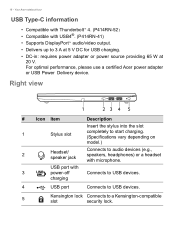
... power source providing 65 W at 20 V. Right view 1 23 4 5 # Icon Item Description Insert the stylus into the slot 1 Stylus slot completely to start charging. (Specifications vary depending on model.) 2 Headset/ speaker jack Connects to audio devices ...(e.g., speakers, headphones) or a headset with 3 power-off Connects to USB devices. For optimal performance, please use a certified Acer power adapter or USB Power Delivery device. Your Acer...
... power source providing 65 W at 20 V. Right view 1 23 4 5 # Icon Item Description Insert the stylus into the slot 1 Stylus slot completely to start charging. (Specifications vary depending on model.) 2 Headset/ speaker jack Connects to audio devices ...(e.g., speakers, headphones) or a headset with 3 power-off Connects to USB devices. For optimal performance, please use a certified Acer power adapter or USB Power Delivery device. Your Acer...

User Manual
Page 19
Insert a paperclip into the hole and press for four seconds. Your Acer notebook tour - 19 # Icon Item Description 3 Rechargeable Remove the pen from the slot and active stylus perform touch actions on the screen. Simulates removing and reinstalling 4 Battery reset pinhole the battery.
Insert a paperclip into the hole and press for four seconds. Your Acer notebook tour - 19 # Icon Item Description 3 Rechargeable Remove the pen from the slot and active stylus perform touch actions on the screen. Simulates removing and reinstalling 4 Battery reset pinhole the battery.

User Manual
Page 22
Note Function may vary depending on apps. Fast-charging Charging time 15 seconds 5 minutes Usage time 90 minutes 100 minutes 22 - Rechargeable Active Stylus RECHARGEABLE ACTIVE STYLUS 3 2 1 # Item Description 1 Eraser button Erases an object. 2 Right-click button Acts like a right mouse button. 3 Charge pin Insert the stylus into the slot completely to start charging.
Note Function may vary depending on apps. Fast-charging Charging time 15 seconds 5 minutes Usage time 90 minutes 100 minutes 22 - Rechargeable Active Stylus RECHARGEABLE ACTIVE STYLUS 3 2 1 # Item Description 1 Eraser button Erases an object. 2 Right-click button Acts like a right mouse button. 3 Charge pin Insert the stylus into the slot completely to start charging.

Lifecycle Extension Guide
Page 8
E F Figure 1-3. Stylus Pen and SIM Card Removal NOTE: NOTE: Make sure the system is completely powered off. 1-6 Disassembly Procedures 5. Insert the eject tool into the hole on the SIM card tray (F). Remove the stylus pen from the stylus pen slot (E) (Figure 1-3). 6. Then push to eject the card tray and remove the SIM card (Figure 1-3).
E F Figure 1-3. Stylus Pen and SIM Card Removal NOTE: NOTE: Make sure the system is completely powered off. 1-6 Disassembly Procedures 5. Insert the eject tool into the hole on the SIM card tray (F). Remove the stylus pen from the stylus pen slot (E) (Figure 1-3). 6. Then push to eject the card tray and remove the SIM card (Figure 1-3).

Lifecycle Extension Guide
Page 25
Disconnect the fingerprint FFC from the LTE board connector (G) (Figure 1-29). 6. Release the LTE board (J) from the I F E H G Figure 1-29. Disconnect the stylus charger cable from the LTE board connector (F) (Figure 1-29) 5. I /O connectors slots and guide pins (K) on the top assembly (Figure 1-30). LTE Board Removal ! WEEE Annex ...
Disconnect the fingerprint FFC from the LTE board connector (G) (Figure 1-29). 6. Release the LTE board (J) from the I F E H G Figure 1-29. Disconnect the stylus charger cable from the LTE board connector (F) (Figure 1-29) 5. I /O connectors slots and guide pins (K) on the top assembly (Figure 1-30). LTE Board Removal ! WEEE Annex ...

Lifecycle Extension Guide
Page 33
B A Figure 1-40. Mainboard Removal Disassembly Procedures 1-31 Detach the tape (A) securing the keyboard backlight FPC connection (Figure 1-40). 2. Mainboard Removal 0 Prerequisite: Ensure that the DIMM Modules, Fan, Heatsink, Stylus Holder, LCD Module, and SSD Module have been disassembled prior removing the mainboard. 1. Remove one (1) screw (B) from the I/O bracket (Figure 1-40).
B A Figure 1-40. Mainboard Removal Disassembly Procedures 1-31 Detach the tape (A) securing the keyboard backlight FPC connection (Figure 1-40). 2. Mainboard Removal 0 Prerequisite: Ensure that the DIMM Modules, Fan, Heatsink, Stylus Holder, LCD Module, and SSD Module have been disassembled prior removing the mainboard. 1. Remove one (1) screw (B) from the I/O bracket (Figure 1-40).

Lifecycle Extension Guide
Page 51
Description 11 Left Speaker 12 LTE Board 13 DB FFC 14 Right I/O Bracket 15 Stylus Pen 16 Stylus Holder 17 Stylus Charger Cable 18 Mainboard 19 Card Reader Board 20 Left I/O Bracket 21 Fan 22 Heatsink 23 WLAN Module 24 DIMM Module 25 SSD Module 26 Battery Pack 27 Base Cover Exploded Diagrams 1-49 Table 1-2. System Exploded Diagram (Continued) No.
Description 11 Left Speaker 12 LTE Board 13 DB FFC 14 Right I/O Bracket 15 Stylus Pen 16 Stylus Holder 17 Stylus Charger Cable 18 Mainboard 19 Card Reader Board 20 Left I/O Bracket 21 Fan 22 Heatsink 23 WLAN Module 24 DIMM Module 25 SSD Module 26 Battery Pack 27 Base Cover Exploded Diagrams 1-49 Table 1-2. System Exploded Diagram (Continued) No.


