
User Manual
Page 10
... is fully charged. Use the battery only for example, when you come into contact with the leaked fluids, rinse thoroughly with any charger or battery that is achieved only after two or three complete charge and discharge cycles. Short-circuiting the terminals may cause the battery ... center. Always try to replace or remove the battery by yourself. • Device with removable battery: The battery should only be replaced by Acer. 10 - Battery performance is left in battery must not occur at temperatures below freezing. Do not attempt to keep the battery between 15°...
... is fully charged. Use the battery only for example, when you come into contact with the leaked fluids, rinse thoroughly with any charger or battery that is achieved only after two or three complete charge and discharge cycles. Short-circuiting the terminals may cause the battery ... center. Always try to replace or remove the battery by yourself. • Device with removable battery: The battery should only be replaced by Acer. 10 - Battery performance is left in battery must not occur at temperatures below freezing. Do not attempt to keep the battery between 15°...

Lifecycle Extension Guide
Page 25
.... 8. Remove two (2) screws (I F E H G Figure 1-29. I ) securing the LTE board (Figure 1-29). Disconnect the fingerprint FFC from the LTE board connector (G) (Figure 1-29). 6. Disconnect the stylus charger cable from the LTE board connector (F) (Figure 1-29) 5. LTE Board Removal Disassembly Procedures 1-23 Disconnect the DB FFC from the I/O connectors slots and guide pins...
.... 8. Remove two (2) screws (I F E H G Figure 1-29. I ) securing the LTE board (Figure 1-29). Disconnect the fingerprint FFC from the LTE board connector (G) (Figure 1-29). 6. Disconnect the stylus charger cable from the LTE board connector (F) (Figure 1-29) 5. LTE Board Removal Disassembly Procedures 1-23 Disconnect the DB FFC from the I/O connectors slots and guide pins...

Lifecycle Extension Guide
Page 51
Description 11 Left Speaker 12 LTE Board 13 DB FFC 14 Right I/O Bracket 15 Stylus Pen 16 Stylus Holder 17 Stylus Charger Cable 18 Mainboard 19 Card Reader Board 20 Left I/O Bracket 21 Fan 22 Heatsink 23 WLAN Module 24 DIMM Module 25 SSD Module 26 Battery Pack 27 Base Cover Exploded Diagrams 1-49 System Exploded Diagram (Continued) No. Table 1-2.
Description 11 Left Speaker 12 LTE Board 13 DB FFC 14 Right I/O Bracket 15 Stylus Pen 16 Stylus Holder 17 Stylus Charger Cable 18 Mainboard 19 Card Reader Board 20 Left I/O Bracket 21 Fan 22 Heatsink 23 WLAN Module 24 DIMM Module 25 SSD Module 26 Battery Pack 27 Base Cover Exploded Diagrams 1-49 System Exploded Diagram (Continued) No. Table 1-2.
Safety Guide
Page 16
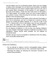
Never use any charger or battery that is especially limited in temperatures well below freezing.... Do not dispose of batteries according to local regulations. authorized repair facility. • Recharge the battery by an Acer- Always try to replace a built-in rechargeable battery, battery replacement must be done by following the instruction included ... or pen causes direct connection of the positive (+) and negative (-) terminals of the battery will be susceptible to www.acer.com for example, when you carry a spare battery in a fire as household waste. Internal battery • Do ...
Never use any charger or battery that is especially limited in temperatures well below freezing.... Do not dispose of batteries according to local regulations. authorized repair facility. • Recharge the battery by an Acer- Always try to replace a built-in rechargeable battery, battery replacement must be done by following the instruction included ... or pen causes direct connection of the positive (+) and negative (-) terminals of the battery will be susceptible to www.acer.com for example, when you carry a spare battery in a fire as household waste. Internal battery • Do ...


