Acer TravelMate 8471 Series Service Guide
Page 7
...14 Lock Keys and embedded numeric keypad 14 Windows Keys 15 Hot Keys 16 Using the system utilities 17 Acer Backup Manager 19 Power management 20 Acer PowerSmart key 20 Acer eRecovery Management 20 Burn backup discs 21 Restore 21 Hardware Specifications and Configurations 23 BIOS Setup Utility 27 System... 38 Before You Begin 38 Disassembly Procedure Flowchard 39 Main unit disassembly flow chart 39 LCM module disassembly flow chart 39 Removing the Battery Pack 40 Removing the HDD and RAM 41 Remove Keyboard 44 Remove FFC of main board and sub board 45 Remove Panel 48 ...
...14 Lock Keys and embedded numeric keypad 14 Windows Keys 15 Hot Keys 16 Using the system utilities 17 Acer Backup Manager 19 Power management 20 Acer PowerSmart key 20 Acer eRecovery Management 20 Burn backup discs 21 Restore 21 Hardware Specifications and Configurations 23 BIOS Setup Utility 27 System... 38 Before You Begin 38 Disassembly Procedure Flowchard 39 Main unit disassembly flow chart 39 LCM module disassembly flow chart 39 Removing the Battery Pack 40 Removing the HDD and RAM 41 Remove Keyboard 44 Remove FFC of main board and sub board 45 Remove Panel 48 ...
Acer TravelMate 8471 Series Service Guide
Page 10
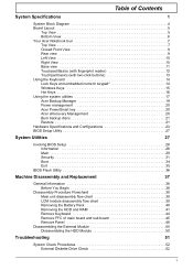
...EDGE (850/900/1800/ 1900 MHz)* ‰ LAN: Gigabit Ethernet; Wake-on-LAN ready Privacy control ‰ Enhanced Acer DASP (Disk Anti-Shock Protection) ‰ Acer Bio-Protection fingerprint solution* ‰ BIOS user, supervisor, HDD passwords ‰ Kensington lock slot Dimensions and weight ‰...; 314.9 (W) x 235 (D) x 25.9/29.6 (H) mm (13.46 x 9.25 x 1.01/1.16 inches) ‰ 1.98 kg (4.37 lbs.) with 6-cell battery pack Power subsystem...
...EDGE (850/900/1800/ 1900 MHz)* ‰ LAN: Gigabit Ethernet; Wake-on-LAN ready Privacy control ‰ Enhanced Acer DASP (Disk Anti-Shock Protection) ‰ Acer Bio-Protection fingerprint solution* ‰ BIOS user, supervisor, HDD passwords ‰ Kensington lock slot Dimensions and weight ‰...; 314.9 (W) x 235 (D) x 25.9/29.6 (H) mm (13.46 x 9.25 x 1.01/1.16 inches) ‰ 1.98 kg (4.37 lbs.) with 6-cell battery pack Power subsystem...

Acer TravelMate 8471 Series Service Guide
Page 17
Closed Front View No. Fully charged: The light shows blue when in -1 card reader Rear view Description Indicates the computer's battery status. 1. Accepts Secure Digital (SD), MultiMediaCard (MMC), Memory Stick (MS), Memory Stick PRO (MS PRO), xD-Picture Card (xD). Only one card can operate at any given time. No. Chapter 1 9 NOTE: Push to remove/install the card. Charging: The light shows amber when the battery is charging. 2. Icon Item 1 Battery 2 Multi-in AC mode. Icon Item 1 Battery bay Description Houses the computer's battery pack.
Closed Front View No. Fully charged: The light shows blue when in -1 card reader Rear view Description Indicates the computer's battery status. 1. Accepts Secure Digital (SD), MultiMediaCard (MMC), Memory Stick (MS), Memory Stick PRO (MS PRO), xD-Picture Card (xD). Only one card can operate at any given time. No. Chapter 1 9 NOTE: Push to remove/install the card. Charging: The light shows amber when the battery is charging. 2. Icon Item 1 Battery 2 Multi-in AC mode. Icon Item 1 Battery bay Description Houses the computer's battery pack.
Acer TravelMate 8471 Series Service Guide
Page 19
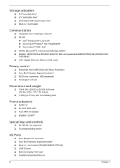
...Wrap the computer security lock cable around an immovable object such as a table or handle of the fan. 6 Battery release latch Releases the battery for removal. Insert the lock into the notch and turn the key to stay cool, even after cooling fan ...available. NOTE: Do not cover or obstruct the opening of a locked drawer. Base view No. Icon Item 1 Battery bay Description Houses the computer's battery pack. 2 Battery lock Locks the battery in position. 3 Memory Houses the computer's main memory. No. Icon Item Description 5 Kensington lock slot Connects ...
...Wrap the computer security lock cable around an immovable object such as a table or handle of the fan. 6 Battery release latch Releases the battery for removal. Insert the lock into the notch and turn the key to stay cool, even after cooling fan ...available. NOTE: Do not cover or obstruct the opening of a locked drawer. Base view No. Icon Item 1 Battery bay Description Houses the computer's battery pack. 2 Battery lock Locks the battery in position. 3 Memory Houses the computer's main memory. No. Icon Item Description 5 Kensington lock slot Connects ...
Acer TravelMate 8471 Series Service Guide
Page 33
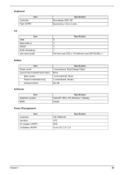
..., Green) On KB Software Item Operation system BIOS Specification Vista SP1/SP2, XP, Windows 7 (Ready) Insyde Power Management Item Controller Interface AC adapter (AVAP) 1st Battery (AVAP) ITE ITE8512F LPC 65W 6 cell 2.6 / 2.8 / 2.9 Specification Chapter 1 25
..., Green) On KB Software Item Operation system BIOS Specification Vista SP1/SP2, XP, Windows 7 (Ready) Insyde Power Management Item Controller Interface AC adapter (AVAP) 1st Battery (AVAP) ITE ITE8512F LPC 65W 6 cell 2.6 / 2.8 / 2.9 Specification Chapter 1 25
Acer TravelMate 8471 Series Service Guide
Page 34
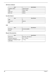
LED Status Indicator Item 1st Battery Status HDD Caps Lock Num Lock 1 (Blue/Orange) 1 (Blue / flash) 1 (Blue) 1 (Blue) Specification Security Features Item TPM Finger print PBA 1 Optional 1 Specification FAN Item Not Noise Number as low as possible 1 Specification Physical Characteristics Item Dimensions Thickness (maximum) Weight (incl 1st Battery & super multi ODD) Specification 323.6 (W) x 228 (D) mm 23.3 ~ 27.9mm < 1.7 kg 26 Chapter 1
LED Status Indicator Item 1st Battery Status HDD Caps Lock Num Lock 1 (Blue/Orange) 1 (Blue / flash) 1 (Blue) 1 (Blue) Specification Security Features Item TPM Finger print PBA 1 Optional 1 Specification FAN Item Not Noise Number as low as possible 1 Specification Physical Characteristics Item Dimensions Thickness (maximum) Weight (incl 1st Battery & super multi ODD) Specification 323.6 (W) x 228 (D) mm 23.3 ~ 27.9mm < 1.7 kg 26 Chapter 1
Acer TravelMate 8471 Series Service Guide
Page 44
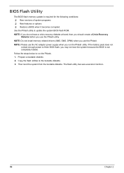
NOTE: Please use the AC adaptor power supply when you use the Phlash. Then boot the system from the bootable diskette. If the battery pack does not contain enough power to run the Phlash utility. Copy the flash utilities to update the system BIOS flash ROM. NOTE: If you ...
NOTE: Please use the AC adaptor power supply when you use the Phlash. Then boot the system from the bootable diskette. If the battery pack does not contain enough power to run the Phlash utility. Copy the flash utilities to update the system BIOS flash ROM. NOTE: If you ...
Acer TravelMate 8471 Series Service Guide
Page 46
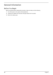
Turn off the power to the system and all power and signal cables from the system. 3. Remove the battery pack. 38 Chapter 3 Unplug the AC adapter and all peripherals. 2. General Information Before You Begin Before proceeding with the disassembly procedure, make sure that you do the following: 1.
Turn off the power to the system and all power and signal cables from the system. 3. Remove the battery pack. 38 Chapter 3 Unplug the AC adapter and all peripherals. 2. General Information Before You Begin Before proceeding with the disassembly procedure, make sure that you do the following: 1.
Acer TravelMate 8471 Series Service Guide
Page 47
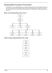
Main unit disassembly flow chart Start Battery HDD RAM BTCB Audio Board VGA Board I/O Board LCM module disassembly flow chart Start Main Board LCM Mylar LCM Module LCM Bezel LCM Panel Chapter 3 39 Disassembly Procedure Flowchard The flowchart on the succeeding page gives you a graphic representation on the entire disassembly sequence and instructs you on the components that need to remove the system board, you want to be removed during servicing. For example, if you must first remove the keyboard, then disassemble the inside assembly frame in that order.
Main unit disassembly flow chart Start Battery HDD RAM BTCB Audio Board VGA Board I/O Board LCM module disassembly flow chart Start Main Board LCM Mylar LCM Module LCM Bezel LCM Panel Chapter 3 39 Disassembly Procedure Flowchard The flowchart on the succeeding page gives you a graphic representation on the entire disassembly sequence and instructs you on the components that need to remove the system board, you want to be removed during servicing. For example, if you must first remove the keyboard, then disassemble the inside assembly frame in that order.
Acer TravelMate 8471 Series Service Guide
Page 48
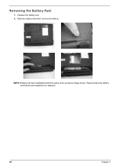
NOTE: Battery has been highlighted with the yellow circle as above image shows. Please detach the battery and follow local regulations for disposal. 40 Chapter 3 Removing the Battery Pack 1. Release the battery lock. 2. Slide the battery latch then remove the battery.
NOTE: Battery has been highlighted with the yellow circle as above image shows. Please detach the battery and follow local regulations for disposal. 40 Chapter 3 Removing the Battery Pack 1. Release the battery lock. 2. Slide the battery latch then remove the battery.
Acer TravelMate 8471 Series Service Guide
Page 50
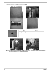
Please detach the RTC battery and follow local regulations for disposal. 42 Chapter 3 Remove the screw on RAM cover and remove RAM. 2. Type M2*5(4.5D*0.8T) Number 1 NOTE: RTC battery has been highlighted with the yellow circle as above image shows.
Please detach the RTC battery and follow local regulations for disposal. 42 Chapter 3 Remove the screw on RAM cover and remove RAM. 2. Type M2*5(4.5D*0.8T) Number 1 NOTE: RTC battery has been highlighted with the yellow circle as above image shows.
Acer TravelMate 8471 Series Service Guide
Page 61
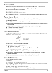
... correct. 3. If the power-on indicator does not light up, check the power cord of the following power sources: 1. Check the Battery Pack To check the battery pack, do the following : From Software: 1. This helps you suspect a power problem, see "Undetermined Problems" on the screen, or...Pin 1: +19 to the diagnostic memory in the test items. 4. Repeat the steps 1 and 2, for correct continuity and installation. 4. Remove the battery pack. 2. z If the voltage is supplied. 3. then check that the DIMM is not corrected, see the appropriate power supply check in control Panel...
... correct. 3. If the power-on indicator does not light up, check the power cord of the following power sources: 1. Check the Battery Pack To check the battery pack, do the following : From Software: 1. This helps you suspect a power problem, see "Undetermined Problems" on the screen, or...Pin 1: +19 to the diagnostic memory in the test items. 4. Repeat the steps 1 and 2, for correct continuity and installation. 4. Remove the battery pack. 2. z If the voltage is supplied. 3. then check that the DIMM is not corrected, see the appropriate power supply check in control Panel...
Acer TravelMate 8471 Series Service Guide
Page 62
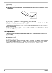
...touchpad pointer. Re-install the battery pack. Replace the system board. After you use a discharged battery pack or a battery pack that has less than 7.5 Vdc after recharging, replace the battery. From Hardware: 1. If the battery status indicator does not light up , replace the battery pack. This symptom is applied... indicator still does not light up, replace the DC/DC charger board. Do not replace a non-defective FRU: 1. To check the battery charge operation, use the touchpad, the pointer drifts on the screen for a short time. No service actions are necessary if the pointer ...
...touchpad pointer. Re-install the battery pack. Replace the system board. After you use a discharged battery pack or a battery pack that has less than 7.5 Vdc after recharging, replace the battery. From Hardware: 1. If the battery status indicator does not light up , replace the battery pack. This symptom is applied... indicator still does not light up, replace the DC/DC charger board. Do not replace a non-defective FRU: 1. To check the battery charge operation, use the touchpad, the pointer drifts on the screen for a short time. No service actions are necessary if the pointer ...
Acer TravelMate 8471 Series Service Guide
Page 64
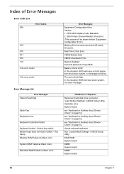
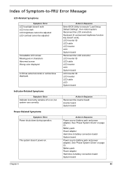
... Monitor type does not match CMOS - Real Time Clock Error. "Load Default Settings" in Sequence Reconnect hard disk drive connector. Unlock external keyboard. CMOS Battery Bad. Battery critical LOW. see "Keyboard or Auxiliary Input Device Check" on page 52. CMOS Checksum Error. Index of Error Messages Error Code List 006 Error Codes...
... Monitor type does not match CMOS - Real Time Clock Error. "Load Default Settings" in Sequence Reconnect hard disk drive connector. Unlock external keyboard. CMOS Battery Bad. Battery critical LOW. see "Keyboard or Auxiliary Input Device Check" on page 52. CMOS Checksum Error. Index of Error Messages Error Code List 006 Error Codes...
Acer TravelMate 8471 Series Service Guide
Page 65
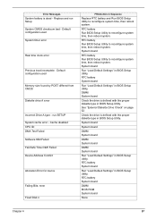
...System board Run "Load Default Settings" in BIOS Setup Utility. RTC battery System board DIMM BIOS ROM System board None Chapter 4 57 RTC battery Run BIOS Setup Utility to reconfigure system time, then reboot system. RTC battery System board Run "Load Default Settings" in BIOS Setup Utility. ... Utility to reconfigure system time, then reboot system. Check the drive is defined with the proper diskette type in Sequence Replace RTC battery and Run BIOS Setup Utility to reconfigure system time, then reboot system. Default configuration used System timer error Real time clock error ...
...System board Run "Load Default Settings" in BIOS Setup Utility. RTC battery System board DIMM BIOS ROM System board None Chapter 4 57 RTC battery Run BIOS Setup Utility to reconfigure system time, then reboot system. RTC battery System board Run "Load Default Settings" in BIOS Setup Utility. ... Utility to reconfigure system time, then reboot system. Check the drive is defined with the proper diskette type in Sequence Replace RTC battery and Run BIOS Setup Utility to reconfigure system time, then reboot system. Default configuration used System timer error Real time clock error ...
Acer TravelMate 8471 Series Service Guide
Page 66
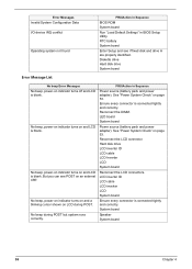
...indicator turns on and a blinking cursor shown on LCD during POST but system runs correctly. No beep during POST. LED board System board Power source (battery pack and power adapter). Diskette drive Hard disk drive System board Error Message List No beep Error Messages No beep, power-on and LCD is... blank. Ensure every connector is blank. RTC battery System board Enter Setup and see POST on page 53. No beep, power-on indicator turns on indicator turns off and LCD is connected tightly...
...indicator turns on and a blinking cursor shown on LCD during POST but system runs correctly. No beep during POST. LED board System board Power source (battery pack and power adapter). Diskette drive Hard disk drive System board Error Message List No beep Error Messages No beep, power-on and LCD is... blank. Ensure every connector is blank. RTC battery System board Enter Setup and see POST on page 53. No beep, power-on indicator turns on indicator turns off and LCD is connected tightly...
Acer TravelMate 8471 Series Service Guide
Page 71
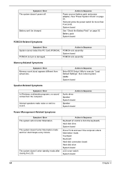
...execute "Load Setup Default Settings", then reboot system. The system doesn't power-on page 53. Battery pack Power adapter Hard drive & battery connection board System board Power source (battery pack and power adapter). Power-Related Symptoms Symptom / Error Power shuts down during operation. Keyboard... See "Power System Check" on . Reconnect the LCD connectors. Action in Sequence Power source (battery pack and power adapter). Battery pack Power adapter Hard drive & battery connection board System board Chapter 4 63 LCD inverter ID LCD cable LCD inverter LCD System board Reconnect...
...execute "Load Setup Default Settings", then reboot system. The system doesn't power-on page 53. Battery pack Power adapter Hard drive & battery connection board System board Power source (battery pack and power adapter). Power-Related Symptoms Symptom / Error Power shuts down during operation. Keyboard... See "Power System Check" on . Reconnect the LCD connectors. Action in Sequence Power source (battery pack and power adapter). Battery pack Power adapter Hard drive & battery connection board System board Chapter 4 63 LCD inverter ID LCD cable LCD inverter LCD System board Reconnect...
Acer TravelMate 8471 Series Service Guide
Page 72
... board PCMCIA slot assembly Memory-Related Symptoms Symptom / Error Memory count (size) appears different from the computer. Action in Sequence Power source (battery pack and power adapter). The system doesn't enter standby mode after closing the LCD. Hold and press the power switch for more than ...4 seconds. System board See "Check the Battery Pack" on page 53. DIMM System board Speaker-Related Symptoms Symptom / Error In Windows, multimedia programs, no sound. Symptom / Error The system...
... board PCMCIA slot assembly Memory-Related Symptoms Symptom / Error Memory count (size) appears different from the computer. Action in Sequence Power source (battery pack and power adapter). The system doesn't enter standby mode after closing the LCD. Hold and press the power switch for more than ...4 seconds. System board See "Check the Battery Pack" on page 53. DIMM System board Speaker-Related Symptoms Symptom / Error In Windows, multimedia programs, no sound. Symptom / Error The system...
Acer TravelMate 8471 Series Service Guide
Page 73
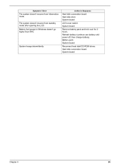
Action in Windows doesn't go higher than 90%. Hard disk connection board System board Chapter 4 65 The system doesn't resume from hibernation mode. Refresh battery (continue use battery until power off, then charge battery). Battery pack System board Reconnect hard disk/CD-ROM drives. Battery fuel gauge in Sequence Hard disk connection board Hard disk drive System board LCD cover switch System board Remove battery pack and let it cool for 2 hours. Symptom / Error The system doesn't resume from standby mode after opening the LCD. System hangs intermittently.
Action in Windows doesn't go higher than 90%. Hard disk connection board System board Chapter 4 65 The system doesn't resume from hibernation mode. Refresh battery (continue use battery until power off, then charge battery). Battery pack System board Reconnect hard disk/CD-ROM drives. Battery fuel gauge in Sequence Hard disk connection board Hard disk drive System board LCD cover switch System board Remove battery pack and let it cool for 2 hours. Symptom / Error The system doesn't resume from standby mode after opening the LCD. System hangs intermittently.
Acer TravelMate 8471 Series Service Guide
Page 76
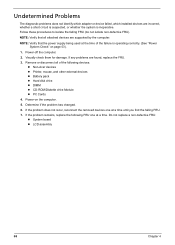
... FRU one at a time. Visually check them for damage. Power-on page 53). 1. If the problem remains, replace the following devices: z Non-Acer devices z Printer, mouse, and other external devices z Battery pack z Hard disk drive z DIMM z CD-ROM/Diskette drive Module z PC Cards 4. Power-off the computer. 2. Do not replace a non-defective...
... FRU one at a time. Visually check them for damage. Power-on page 53). 1. If the problem remains, replace the following devices: z Non-Acer devices z Printer, mouse, and other external devices z Battery pack z Hard disk drive z DIMM z CD-ROM/Diskette drive Module z PC Cards 4. Power-off the computer. 2. Do not replace a non-defective...


