User Manual
Page 1
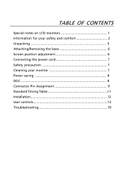
TABLE OF CONTENTS Special notes on LCD monitors 1 Information for your safety and comfort 2 Unpacking 5 Attaching/Removing the base 6 Screen position adjustment 6 Connecting the power cord 7 Safety precaution 7 Cleaning your monitor 7 Power saving 8 DDC 8 Connector Pin Assignment 9 Standard Timing Table 11 Installation 12 User controls 13 Troubleshooting 19
TABLE OF CONTENTS Special notes on LCD monitors 1 Information for your safety and comfort 2 Unpacking 5 Attaching/Removing the base 6 Screen position adjustment 6 Connecting the power cord 7 Safety precaution 7 Cleaning your monitor 7 Power saving 8 DDC 8 Connector Pin Assignment 9 Standard Timing Table 11 Installation 12 User controls 13 Troubleshooting 19
User Manual
Page 2
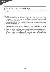
It may include blemishes of 0.01% or less such as a missing pixel or a pixel lit all of the time. · Due to the nature of the LCD screen, an afterimage of the previous screen may remain after switching the image, when the same image is recovered slowly by changing the image or turning off the Power Switch and then turn it on the desktop pattern you use . NOTES · Due to make sure the flicker disappears. · You may flicker during initial use . · The LCD screen has effective pixels of the fluorescent light, the screen may find slightly uneven brightness on the screen ...
It may include blemishes of 0.01% or less such as a missing pixel or a pixel lit all of the time. · Due to the nature of the LCD screen, an afterimage of the previous screen may remain after switching the image, when the same image is recovered slowly by changing the image or turning off the Power Switch and then turn it on the desktop pattern you use . NOTES · Due to make sure the flicker disappears. · You may flicker during initial use . · The LCD screen has effective pixels of the fluorescent light, the screen may find slightly uneven brightness on the screen ...

User Manual
Page 3
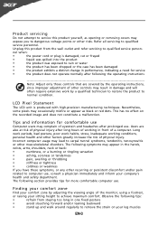
CAUTION for accessibility Be sure that the power outlet you can't hear people speaking near water. • Do not place this product on an unstable cart, stand or table. Safe listening Follow these instructions carefully. Information for your safety and comfort Safety instructions Read these instructions, suggested by placing the product on a bed, sofa, rug or other similar surface. The openings should never be placed near or over a radiator or heat register, or in a built-in a fire or electric shock. This product should never be blocked or covered. If the ...
CAUTION for accessibility Be sure that the power outlet you can't hear people speaking near water. • Do not place this product on an unstable cart, stand or table. Safe listening Follow these instructions carefully. Information for your safety and comfort Safety instructions Read these instructions, suggested by placing the product on a bed, sofa, rug or other similar surface. The openings should never be placed near or over a radiator or heat register, or in a built-in a fire or electric shock. This product should never be blocked or covered. If the ...
User Manual
Page 4
Unplug this product yourself, as black or red dots. nel when: • the power cord or plug is produced with high-precision manufacturing techniques. Nevertheless, some pixels may lead to qualified service personnel. Tips and information for comfortable use , consult a physician immediately and inform your comfort zone by a qualified technician to restore the product to normal condition. The following the operating instructions Note: Adjust only those controls that are also at risk of a computer. LCD Pixel Statement The LCD unit is damaged, cut or frayed • liquid ...
Unplug this product yourself, as black or red dots. nel when: • the power cord or plug is produced with high-precision manufacturing techniques. Nevertheless, some pixels may lead to qualified service personnel. Tips and information for comfortable use , consult a physician immediately and inform your comfort zone by a qualified technician to restore the product to normal condition. The following the operating instructions Note: Adjust only those controls that are also at risk of a computer. LCD Pixel Statement The LCD unit is damaged, cut or frayed • liquid ...
User Manual
Page 5
... clarity. • Eliminate glare and reflections by: • placing your display in recycling, please visit the following websites: Worldwide: http://www.acer-group.com/public/Sustainability/sustainability01.htm http://www.acer-group.com/public/Sustainability/sustainability04.htm EN-4 • take breaks regularly, and do not recommend using the product on how to...
... clarity. • Eliminate glare and reflections by: • placing your display in recycling, please visit the following websites: Worldwide: http://www.acer-group.com/public/Sustainability/sustainability01.htm http://www.acer-group.com/public/Sustainability/sustainability04.htm EN-4 • take breaks regularly, and do not recommend using the product on how to...
User Manual
Page 6
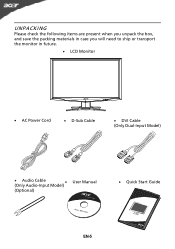
UNPACKING Please check the following items are present when you unpack the box, and save the packing materials in case you will need to ship or transport the monitor in future. · LCD Monitor · AC Power Cord · D-Sub Cable · DVI Cable (Only Dual-Input Model) · Audio Cable (Only Audio-Input Model) · (Optional) User Manual · Quick Start Guide EN-5
UNPACKING Please check the following items are present when you unpack the box, and save the packing materials in case you will need to ship or transport the monitor in future. · LCD Monitor · AC Power Cord · D-Sub Cable · DVI Cable (Only Dual-Input Model) · Audio Cable (Only Audio-Input Model) · (Optional) User Manual · Quick Start Guide EN-5
User Manual
Page 7
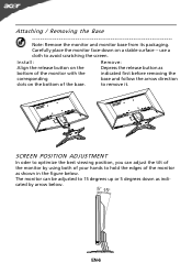
Install: Remove: Align the release button on the Depress the release button as shown in the figure below . Carefully place the monitor face-down as indicated by using both of your hands to 15 degrees up or 5 degrees down on the bottom of the monitor by arrow below . use a cloth to remove it. EN-6 Attaching / Removing the Base Note: Remove the monitor and monitor base from its packaging. to avoid scratching the screen. SCREEN POSITION ADJUSTMENT In oder to optimize the best viewing position, you can be adjusted to hold the edges of the monitor as bottom of...
Install: Remove: Align the release button on the Depress the release button as shown in the figure below . Carefully place the monitor face-down as indicated by using both of your hands to 15 degrees up or 5 degrees down on the bottom of the monitor by arrow below . use a cloth to remove it. EN-6 Attaching / Removing the Base Note: Remove the monitor and monitor base from its packaging. to avoid scratching the screen. SCREEN POSITION ADJUSTMENT In oder to optimize the best viewing position, you can be adjusted to hold the edges of the monitor as bottom of...
User Manual
Page 8
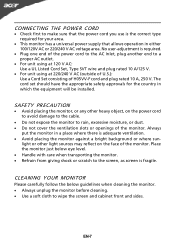
light or other heavy object, on the face of the monitor. CLEANING YOUR MONITOR Please carefully follow the below eye level. · Handle with care when transporting the monitor. · Refrain from giving shock or scratch to make sure that the power cord you use is the correct type required for the country in a place where there is required. · Plug one end of the power cord to the AC Inlet, plug another end to a proper AC outlet. · For unit using at 120 V AC: Use a UL Listed Cord Set, Type SVT wire and plug rated 10 A/125 V. · For unit using at 220/240 V AC (outside ...
light or other heavy object, on the face of the monitor. CLEANING YOUR MONITOR Please carefully follow the below eye level. · Handle with care when transporting the monitor. · Refrain from giving shock or scratch to make sure that the power cord you use is the correct type required for the country in a place where there is required. · Plug one end of the power cord to the AC Inlet, plug another end to a proper AC outlet. · For unit using at 120 V AC: Use a UL Listed Cord Set, Type SVT wire and plug rated 10 A/125 V. · For unit using at 220/240 V AC (outside ...
User Manual
Page 9
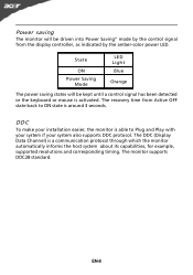
The recovery time from the display controller, as indicated by the control signal from Active OFF state back to Plug and Play with your system if your system also supports DDC protocol. DDC To make your installation easier, the monitor is able to ON state is around 3 seconds. The DDC (Display Data Channel) is a communication protocol through which the monitor automatically informs the host system about its capabilities, for example, supported resolutions and corresponding timing. The monitor supports DDC2B standard. EN-8 Power saving The monitor will be driven into Power ...
The recovery time from the display controller, as indicated by the control signal from Active OFF state back to Plug and Play with your system if your system also supports DDC protocol. DDC To make your installation easier, the monitor is able to ON state is around 3 seconds. The DDC (Display Data Channel) is a communication protocol through which the monitor automatically informs the host system about its capabilities, for example, supported resolutions and corresponding timing. The monitor supports DDC2B standard. EN-8 Power saving The monitor will be driven into Power ...
User Manual
Page 10
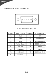
DESCRIPTION Red Green Blue Monitor Ground Self Test R-Ground G-Ground B-Ground PIN NO. 9. 10. 11. 12. 13. 14. 15. DESCRIPTION +5V Logic Ground Monitor Ground DDC-Serial Data H-Sync V-Sync DDC-Serial Clock EN-9 CONNECTOR PIN ASSIGNMENT 5 1 10 6 15 11 15-Pin Color Display Signal Cable PIN NO. 1. 2. 3. 4. 5. 6. 7. 8.
DESCRIPTION Red Green Blue Monitor Ground Self Test R-Ground G-Ground B-Ground PIN NO. 9. 10. 11. 12. 13. 14. 15. DESCRIPTION +5V Logic Ground Monitor Ground DDC-Serial Data H-Sync V-Sync DDC-Serial Clock EN-9 CONNECTOR PIN ASSIGNMENT 5 1 10 6 15 11 15-Pin Color Display Signal Cable PIN NO. 1. 2. 3. 4. 5. 6. 7. 8.
User Manual
Page 11
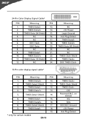
TMDS Data 2/4 Shield 15. 4. NC 16. 5. TMDS Data2 Shield 11. 3. TMDS Data1+ 13. 5. TMDS Data1- 15. 7. TMDS Data2+ 10. 2. on device) SCL SDA DDC/CEC Ground +5V Power Hot Plug Detect 24-Pin Color Display Signal Cable* PIN Meaning PIN 1. NC 24. TMDS Data1 Shield 14. 6. TMDS Data2- 12. 4. TMDS Data0+ 16. 8. TMDS Data2+ 14. 3. TMDS Data0- 18. 19. * only for certain models EN-10 Meaning TMDS Clock+ TMDS Clock Shield TMDS Clock- DDC Clock 18. 7. TMDS Data1- 21. 10. CEC Reserved (N.C. TMDS Data2- 13. 2. ...
TMDS Data 2/4 Shield 15. 4. NC 16. 5. TMDS Data2 Shield 11. 3. TMDS Data1+ 13. 5. TMDS Data1- 15. 7. TMDS Data2+ 10. 2. on device) SCL SDA DDC/CEC Ground +5V Power Hot Plug Detect 24-Pin Color Display Signal Cable* PIN Meaning PIN 1. NC 24. TMDS Data1 Shield 14. 6. TMDS Data2- 12. 4. TMDS Data0+ 16. 8. TMDS Data2+ 14. 3. TMDS Data0- 18. 19. * only for certain models EN-10 Meaning TMDS Clock+ TMDS Clock Shield TMDS Clock- DDC Clock 18. 7. TMDS Data1- 21. 10. CEC Reserved (N.C. TMDS Data2- 13. 2. ...

User Manual
Page 12
Standard Timing Table Mode Resolution 1 VGA 640x480 60 Hz 2 VGA 640x480 72 Hz 3 VGA 640x480 75 Hz 4 MAC 640x480 66.66 Hz 5 VESA 720x400 70 Hz 6 SVGA 800x600 56 Hz 7 SVGA 800x600 60 Hz 8 SVGA 800x600 72 Hz 9 SVGA 800x600 75 Hz 10 MAC 832x624 74.55 Hz 11 XGA 1024x768 60 Hz 12 XGA 1024x768 70 Hz 13 XGA 1024x768 75 Hz 14 MAC 1152x870 75 Hz 15 VESA 1152x864 75 Hz 16 SXGA 1280x1024 60 Hz 17 SXGA 1280x1024 75 Hz 18 WXGA 1280x800 60 Hz 19 WXGA+ 1440x900 60 Hz 20 WXGA+ 1440x900 75 Hz 21 WSXGA+ 1680x1050 60 Hz 22 UXGA 1920x1080 60...
Standard Timing Table Mode Resolution 1 VGA 640x480 60 Hz 2 VGA 640x480 72 Hz 3 VGA 640x480 75 Hz 4 MAC 640x480 66.66 Hz 5 VESA 720x400 70 Hz 6 SVGA 800x600 56 Hz 7 SVGA 800x600 60 Hz 8 SVGA 800x600 72 Hz 9 SVGA 800x600 75 Hz 10 MAC 832x624 74.55 Hz 11 XGA 1024x768 60 Hz 12 XGA 1024x768 70 Hz 13 XGA 1024x768 75 Hz 14 MAC 1152x870 75 Hz 15 VESA 1152x864 75 Hz 16 SXGA 1280x1024 60 Hz 17 SXGA 1280x1024 75 Hz 18 WXGA 1280x800 60 Hz 19 WXGA+ 1440x900 60 Hz 20 WXGA+ 1440x900 75 Hz 21 WSXGA+ 1680x1050 60 Hz 22 UXGA 1920x1080 60...
User Manual
Page 13
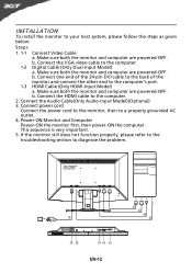
Make sure both the monitor and computer are powered-OFF. Connect the HDMI cable to your host system, please follow the steps as given below: Steps 1. 1-1 Connect Video Cable a. Power-ON Monitor and Computer Power-ON the monitor first, then power-ON the computer. INSTALLATION To install the monitor to the computer. 2. Make sure both the monitor and computer are powered-OFF. b. b. b. Connect power cord Connect the power cord to the monitor, then to the computer. 1-2 Digital Cable (Only Dual-Input Model) a. Connect the VGA video cable to a properly grounded AC outlet. 4. ...
Make sure both the monitor and computer are powered-OFF. Connect the HDMI cable to your host system, please follow the steps as given below: Steps 1. 1-1 Connect Video Cable a. Power-ON Monitor and Computer Power-ON the monitor first, then power-ON the computer. INSTALLATION To install the monitor to the computer. 2. Make sure both the monitor and computer are powered-OFF. b. b. b. Connect power cord Connect the power cord to the monitor, then to the computer. 1-2 Digital Cable (Only Dual-Input Model) a. Connect the VGA video cable to a properly grounded AC outlet. 4. ...
User Manual
Page 14
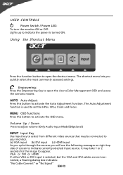
AUTO Auto Adjust: Press this botton to open the Acer eColor Management OSD and access the scenario modes. The shortcut menu lets you will see the following messages on right top side of screen to ...
AUTO Auto Adjust: Press this botton to open the Acer eColor Management OSD and access the scenario modes. The shortcut menu lets you will see the following messages on right top side of screen to ...
User Manual
Page 15
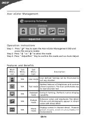
... n a tive d isp lay mode capability N/A Grahpic mode Enhances colors and emphasize fine detail. N/A Movie mode Displays scenes in clearest detail. Acer eColor Management Operation instructions Step 1: Press " " Key to open the Acer eColor Management OSD and access the scenario modes Step 2: Press " " or " " to select the mode Step 3: Press " Adjust/Exit " Key...
... n a tive d isp lay mode capability N/A Grahpic mode Enhances colors and emphasize fine detail. N/A Movie mode Displays scenes in clearest detail. Acer eColor Management Operation instructions Step 1: Press " " Key to open the Acer eColor Management OSD and access the scenario modes Step 2: Press " " or " " to select the mode Step 3: Press " Adjust/Exit " Key...
User Manual
Page 16
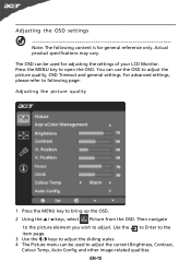
The OSD can be used for general reference only. Use the to Enter to the item page. 3 Use the / keys to adjust the sliding scales. 4 The Picture menu can use the OSD to adjust the picture quality, OSD Timeout and general settings. You can be used to adjust the current Brightness, Contrast, Colour Temp, Auto Config and other image-related qualities. For advanced settings, please refer to following content is for adjusting the settings of your LCD Monitor. Press the MENU key to adjust. EN-15 Then navigate to the picture element you wish to open the OSD. Adjusting the OSD ...
The OSD can be used for general reference only. Use the to Enter to the item page. 3 Use the / keys to adjust the sliding scales. 4 The Picture menu can use the OSD to adjust the picture quality, OSD Timeout and general settings. You can be used to adjust the current Brightness, Contrast, Colour Temp, Auto Config and other image-related qualities. For advanced settings, please refer to following content is for adjusting the settings of your LCD Monitor. Press the MENU key to adjust. EN-15 Then navigate to the picture element you wish to open the OSD. Adjusting the OSD ...

User Manual
Page 17
Adjusting the OSD Timeout 1 Press the MENU key to adjust. Then navigate to the feature you wish to bring up the OSD. 2 Using the directional keys, select OSD from the on screen display. EN-16
Adjusting the OSD Timeout 1 Press the MENU key to adjust. Then navigate to the feature you wish to bring up the OSD. 2 Using the directional keys, select OSD from the on screen display. EN-16
User Manual
Page 18
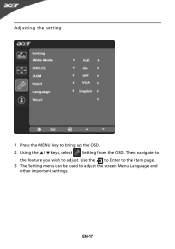
Adjusting the setting 1 Press the MENU key to adjust. EN-17 Then navigate to the feature you wish to bring up the OSD. 2 Using the / keys, select Setting from the OSD. Use the to Enter to the item page. 3 The Setting menu can be used to adjust the screen Menu Language and other important settings.
Adjusting the setting 1 Press the MENU key to adjust. EN-17 Then navigate to the feature you wish to bring up the OSD. 2 Using the / keys, select Setting from the OSD. Use the to Enter to the item page. 3 The Setting menu can be used to adjust the screen Menu Language and other important settings.

User Manual
Page 19
Product information 1920 x 1080 H: 67KHz V: 60Hz VGA Input S/N:ETL53091326350380B3742 1 Press the MENU key to bring up for current input. EN-18 Then the basic information of LCD monitor will show up the OSD. 2 Using the / keys, select Information from the OSD.
Product information 1920 x 1080 H: 67KHz V: 60Hz VGA Input S/N:ETL53091326350380B3742 1 Press the MENU key to bring up for current input. EN-18 Then the basic information of LCD monitor will show up the OSD. 2 Using the / keys, select Information from the OSD.
User Manual
Page 20
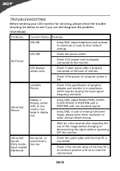
TROUBLESHOOTING Before sending your LCD monitor for a few seconds after adjusting the size of graphics adapter and monitor is in minimum position and try to raise the volume level. LED OFF · Check the power switch. Unstable Picture · Check if the specification of the image before changing or disconnecting the signal cable or powering OFF the monitor. EN-19 No Picture · Check if AC power cord is · Using OSD, adjust RESOLUTION, CLOCK, missing, center CLOCK-PHASE, H-POSITION and V- Abnormal Picture Display is properly connected to their ...
TROUBLESHOOTING Before sending your LCD monitor for a few seconds after adjusting the size of graphics adapter and monitor is in minimum position and try to raise the volume level. LED OFF · Check the power switch. Unstable Picture · Check if the specification of the image before changing or disconnecting the signal cable or powering OFF the monitor. EN-19 No Picture · Check if AC power cord is · Using OSD, adjust RESOLUTION, CLOCK, missing, center CLOCK-PHASE, H-POSITION and V- Abnormal Picture Display is properly connected to their ...
